This thesis explores low power context aware hierarchical system design through the development and deployment of systems for geospatial and medical applications. The thesis is directed by Dr. Nilanjan Banerjee and Dr. Ryan Robucci of the Department of Computer Science and Electrical Engineering. The abstract describes the research objective as exploring various hierarchical architectures to approach the problem of designing ultra low power embedded systems from the system and application integration level.
[DOCUMENT]
APPROVAL SHEET
Title of Thesis: Low Power Context Aware Hierarchical System Design
Name of Candidate: Stanislav Bobovych
Computer Engineering PhD,
2020
Thesis and Abstract Approved:
Nilanjan Banerjee
Associ


![101
SunaPlayer can support. The range is defined as the smallest and largest output current
and output voltage that the SunaPlayer can generate with high accuracy. To determine the
smallest voltage and smallest current, we set V+ to the smallest value that our system can
support (5V), and then reduce the bias voltage (Vbe) to as small as possible so that the dar-
lington is in active and not in cutoff mode. This bias voltage switches on the darlington
by the smallest possible amount. We then try a set of load impedances and measure the
voltage drop across the load and its current draw with a high resolution multimeter and our
measurement circuit simultaneously. We determine the error in the measurement, and if the
error is below a threshold, we assume that the system can generate the output voltage and
current. To measure the largest possible current and voltage, we set V+ to the maximum
value that the SunaPlayer can support (10V). We then increase the bias voltage so that the
darlington is in active mode and not in saturation and measure the largest possible output
voltage and current. Through this experiment, we found that the SunaPlayer can accurately
generate output voltages spanning 0.02 V to 9.8 V (at low currents), and output currents
from 430 µA to 1.89 A (at an output voltage of 2.12 V). The analog-to-digital converter
induces a noise of +/- 1.5% when measuring low voltages around 0.02 V, and induces an
error of 0.03 V when measuring high voltages (9.8V). It also induces a 7% error at ultra-
low currents. The error is caused by an offset voltage of the instrumentation amplifier. For
the higher current values, the heat dissipated by the darlington is a bottleneck. Even with
the processor fan, there is a steep rise in the darlington temperature. We believe that with a
passive heat sink, the range can be further improved. In spite of the above, the SunaPlayer
can support output voltages that span three orders of magnitude and currents that span four
orders of magnitude. The system can, therefore, emulate a wide range of solar cells under
a wide range of lighting conditions.
We next evaluate the accuracy of the SunaPlayer. The accuracy of converging to an
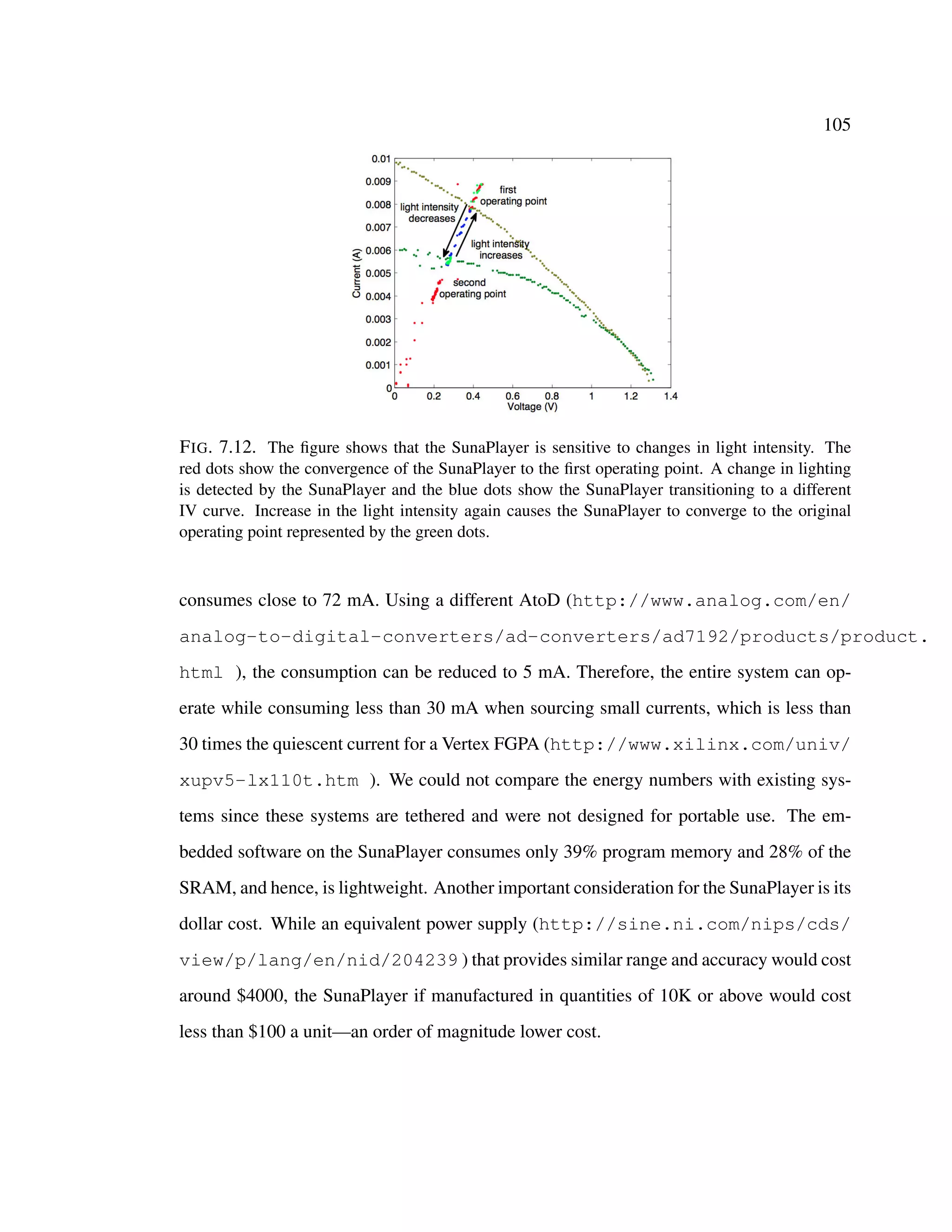
operating point on the IV curve is calculated as a duple [(CI − AI)/AI, (CV − AV )/AV ],](https://image.slidesharecdn.com/thesissmall-200505154139/75/Thesis-small-121-2048.jpg)
![102
where AV , AI are the operating voltage and current for the given load and CV , CI are the
output voltage and current of the SunaPlayer when the system is in the Stable state
(see Figure 7.6). To determine the accuracy across a range of solar panels and lighting
conditions, we perform our experiments in a laboratory setting using the three IV traces
described in Table 7.1. For each IV trace, the SunaPlayer powers small, medium, and large
loads. These loads correspond to the [low voltage, high current], [medium voltage, medium
current], and [high voltage, low current] regions of the IV trace and vary from 45 Ω to 2.1
KΩs. We perform five experimental runs for every load and every IV trace, and calculate
the average accuracy and the standard deviation. Figure 7.9 plots the voltage and current
convergence errors for the SunaPlayer for the three IV traces. We find that the average
accuracy is high–close to 99% for most cases. The overall accuracy of converging to the
correct current value is higher than the voltage values. This is because the resolution of
our current measurement circuit is higher than our voltage measurement circuit. Overall,
the system can accurately converge to the correct operating voltage and current for a wide
range of solar panels and lighting conditions.
Latency: We next measure the latency of converging to the operating points on the three IV
traces. We use the same set of experiments described above for the accuracy measurements.
Figure 7.10 shows the latency of converging to an operating point in seconds. In the worst
case, the SunaPlayer incurs a latency of 10 seconds to converge to an operating point from
cutoff mode (0 output voltage and 0 output current). Note that this is the absolute worst case
latency of convergence of the SunaPlayer. We show in the next section (sensitivity) that the
system responds to changes in lighting conditions quickly (in less than 2 seconds)—the
latency is similar to that reported in previous solar emulation platforms (Li & Chou 2004).
To understand the latency of the SunaPlayer, we break down the average latency into the
fraction of time spent on measuring the output voltage and current and the time taken by
the state machine algorithm. The primary bottleneck of the system is in measuring the](https://image.slidesharecdn.com/thesissmall-200505154139/75/Thesis-small-122-2048.jpg)


![REFERENCES
[1] Agarwal, Y.; Hodges, S.; Chandra, R.; Scott, J.; Bahl, P.; and Gupta, R. 2009. Som-
niloquy: augmenting network interfaces to reduce pc energy usage. NSDI’09, 365–380.
Berkeley, CA, USA: USENIX Association.
[2] Banerjee, N.; Sorber, J.; Corner, M. D.; Rollins, S.; and Ganesan, D. 2007. Triage:
Balancing Energy and Quality of Service in a Microserver. In Proceedings of ACM
MobiSys.
[3] Banerjee, N.; Corner, M. D.; and Levine, B. N. 2007. An Energy-Efficient Architecture
for DTN Throwboxes. In IEEE Infocom.
[4] Banerjee, N.; Rollins, S.; and Moran, K. 2011. Automating energy management in
green homes. In Proceedings of the 2nd ACM SIGCOMM workshop on Home networks,
HomeNets ’11, 19–24. New York, NY, USA: ACM.
[5] Bauer, A.; Cassel, W.; Benes, H.; Kesper, K.; Rye, D.; Sica, D.; W Winkelman, J.;
Bauer, L.; Grieger, F.; Joeres, L.; Moran, K.; Schollmayer, E.; Whitesides, J.; C Carney,
H.; S Walters, A.; Oertel, W.; and Trenkwalder, C. 2016. Rotigotine’s effect on plm-
associated blood pressure elevations in restless legs syndrome: An rct. 86.
[6] Bridenbaugh, S. A., and Kressig, R. W. 2010. Laboratory review: the role of gait
analysis in seniors mobility and fall prevention. Gerontology 57(3):256–264.
[7] Brunelli, D.; Benini, L.; Moser, C.; and Thiele, L. 2008. An efficient solar energy
harvester for wireless sensor nodes. In Proceedings of the conference on Design, au-
tomation and test in Europe, DATE ’08, 104–109. New York, NY, USA: ACM.
113](https://image.slidesharecdn.com/thesissmall-200505154139/75/Thesis-small-133-2048.jpg)
![114
[8] Center of Disease Control and Prevention. 2010. Falls among older adults: An
overview. http://www.cdc.gov/homeandrecreationalsafety/falls/
adultfalls.html. Accessed: 2019-08-25.
[9] Chou, P.; Park, C.; Park, J.; Pham, K.; and Liu, J. 2003. B#: a battery emulator and
power profiling instrument. In ISLPED ’03.
[10] Clark, S. S.; Gummeson, J.; Fu, K.; and Ganesan, D. 2009. Towards autonomously-
powered CRFIDs. In Workshop on Power Aware Computing and Systems (HotPower
2009).
[11] Dr Peter Harrop, Mr James Hayward, R. D., and Holland, G. 2015. Wearable tech-
nology 2015-2025: Technologies, markets, forecasts. Technical report, IDTechEx.
[12] E Martin, S.; M Engleman, H.; J Deary, I.; and J Douglas, N. 1996. The effect of
sleep fragmentation on daytime function. 153:1328–32.
[13] E. Martin, S.; Brander, P.; J. Deary, I.; and J. Douglas, N. 2000. The effect of clustered
versus regular sleep fragmentation on daytime function. 8:305–11.
[14] Fesquet, L.; Sicard, G.; and Bid´egaray-Fesquet, B. 2010. Targeting ultra-low power
consumption with non-uniform sampling and filtering. In Circuits and Systems (ISCAS),
Proceedings of 2010 IEEE International Symposium on, 3585–3588. IEEE.
[15] Gabelia, D.; Mitterling, T.; Hgl, B.; Wenning, G.; and Frauscher, B. 2014. Do
periodic arm movements during sleep exist in healthy subjects? a polysomnographic
study. 15.
[16] Govil, K.; Chan, E.; and Wasserman, H. 1995. Comparing algorithms for dynamic
speed-setting of a low-power CPU. In Proceedings of the First ACM International Con-
ference on Mobile Computing and Networking (MobiCom’95).](https://image.slidesharecdn.com/thesissmall-200505154139/75/Thesis-small-134-2048.jpg)
![115
[17] Grim, K.; Lee, B.; Y Sung, A.; and Kotagal, S. 2013. Treatment of childhood-
onset restless legs syndrome and periodic limb movement disorder using intravenous
iron sucrose. 14.
[18] Gruetter, J. 2011. Squeezing out power. http://powerelectronics.com/
energy-harvesting/squeezing-out-power.
[19] Gr¨undler, P. 2007. Conductivity sensors and capacitive sensors. Chemical sensors:
An introduction for scientists and engineers 123–132.
[20] Gummeson, J.; Clark, S. S.; Fu, K.; and Ganesan, D. 2010. On the limits of effec-
tive micro-energy harvesting on mobile CRFID sensors. In Proceedings of 8th Annual
ACM/USENIX International Conference on Mobile Systems, Applications, and Services
(MobiSys 2010). To appear.
[21] Hammons, T. 2008. Integrating renewable energy sources into european grids. Inter-
national Journal of Electrical Power & Energy Systems 30(8):462 – 475.
[22] Helbostad, J. L., and Moe-Nilssen, R. 2003. The effect of gait speed on lateral balance
control during walking in healthy elderly. Gait & posture 18(2):27–36.
[23] Helmbold, D. P.; Long, D. D. E.; and Sherrod, B. 1996. A dynamic disk spin-
down technique for mobile computing. In Proceedings of the Second ACM International
Conference on Mobile Computing and Networking (MobiCom’96).
[24] Hempstead, M.; Tripathi, N.; Mauro, P.; Wei, G.-Y.; and Brooks, D. 2005. An
ultra low power system architecture for sensor network applications. In ACM SIGARCH
Computer Architecture News, volume 33, 208–219. IEEE Computer Society.](https://image.slidesharecdn.com/thesissmall-200505154139/75/Thesis-small-135-2048.jpg)
![116
[25] Hester, J.; Scott, T.; and Sorber, J. 2014. Ekho: Realistic and repeatable experimen-
tation for tiny energy-harvesting sensors. In Proceedings of the 12th ACM Conference
on Embedded Network Sensor Systems, SenSys ’14, 1–15. New York, NY, USA: ACM.
[26] Huang, H.; Pillai, P.; and Shin, K. G. 2003. Design and implementation of power-
aware virtual memory. In Proceedings of USENIX Technical Conference.
[27] Institute of Medicine. 2006. Sleep disorders and sleep deprivation: An unmet public
health problem. Washington, DC: The National Academies Press.
[28] Kansal, A.; Hsu, J.; Zahedi, S.; and Srivastava, M. B. 2006. Power management
in energy harvesting sensor networks. ACM Transactions on Embedded Computing
Systems.
[29] Karout, H.; Diab, M.; Moslem, B.; Alkhatib, R.; Corbier, C.; and Badaoui, M. E.
2015. Frequency content analysis of gaitvertical ground reaction force. In Advances in
Biomedical Engineering (ICABME), 2015 International Conference on, 53–56. IEEE.
[30] Kern, R., and Wagemann, H.-G. 1987. Uncomplicated measurement procedure for
i-v-characteristics of photovoltaic generators at remote sites. 314–318.
[31] Krause, A.; Ihmig, M.; Rankin, E.; Leong, D.; Gupta, S.; Siewiorek, D.; Smailagic,
A.; Deisher, M.; and Sengupta, U. 2005. Trading off prediction accuracy and power
consumption for context-aware wearable computing. In Wearable Computers, 2005.
Proceedings. Ninth IEEE International Symposium on, 20–26. IEEE.
[32] L Marcus, C.; Traylor, J.; R Gallagher, P.; Brooks, L.; Huang, J.; Koren, D.; Katz, L.;
B.A. Mason, T.; and E Tapia, I. 2014. Prevalence of periodic limb movements during
sleep in normal children. 37:1349–52.](https://image.slidesharecdn.com/thesissmall-200505154139/75/Thesis-small-136-2048.jpg)
![117
[33] L Picchietti, D., and Stevens, H. 2007. Early manifestations of restless legs syndrome
in childhood and adolescence. 9:770–81.
[34] Lee, S. I.; Ozsecen, M. Y.; Della Toffola, L.; Daneault, J.-F.; Puiatti, A.; Patel, S.; and
Bonato, P. 2015. Activity detection in uncontrolled free-living conditions using a single
accelerometer. In Wearable and Implantable Body Sensor Networks (BSN), 2015 IEEE
12th International Conference on, 1–6. IEEE.
[35] Lee, S.; Buxton, W.; and Smith, K. C. 1985. A multi-touch three dimensional touch-
sensitive tablet. In ACM CHI, CHI ’85, 21–25. New York, NY, USA: ACM.
[36] Li, D., and Chou, P. H. 2004. Maximizing efficiency of solar-powered systems by
load matching. ISLPED ’04.
[37] Li, X.; Allen, R.; J. Earley, C.; Liu, H.; E. Cruz, T.; Edden, R.; B. Barker, P.; and van
zijl, P. 2016. Brain iron deficiency in idiopathic restless legs syndrome measured by
quantitative magnetic susceptibility at 7 tesla. 22.
[38] Lin, K.; Hsu, J.; Zahedi, S.; Lee, D. C.; Friedman, J.; Kansal, A.; Raghunathan, V.;
and Srivastava, M. B. 2005. Heliomote: Enabling long-lived sensor networks through
solar energy harvesting. In Proceedings of ACM Sensys.
[39] Liu, J.; Chou, P. H.; Bagherzadeh, N.; and Kurdahi, F. 2001. Power-aware scheduling
under timing constraints for mission-critical embedded systems. In Proceedings of the
38th annual Design Automation Conference, 840–845. ACM.
[40] Lo, P.-H.; Hong, C.; Lo, S.-C.; and Fang, W. 2011. Implementation of inductive
proximity sensor using nanoporous anodic aluminum oxide layer. In TRANSDUCERS,
1871–1874. IEEE.](https://image.slidesharecdn.com/thesissmall-200505154139/75/Thesis-small-137-2048.jpg)
![118
[41] Lo, P.-H.; Hong, C.; Tseng, S.-H.; Yeh, J.-H.; and Fang, W. 2012. Implementation
of vertical-integrated dual mode inductive-capacitive proximity sensor. In IEEE MEMS,
640–643. IEEE.
[42] Lorch, J. 1995. A complete picture of the energy consumption of a portable computer.
Technical report.
[43] Lu, T. 2013. A motion control method of intelligent wheelchair based on hand gesture
recognition. In ICIEA 2013, 957–962. IEEE.
[44] M Kelly, J.; Strecker, R.; and Bianchi, M. 2012. Recent developments in home
sleep-monitoring devices. 2012:768794.
[45] Maki, B. E. 1997. Gait changes in older adults: predictors of falls or indicators of
fear. Journal of the American geriatrics society 45(3):313–320.
[46] Mantua, J.; Gravel, N.; and Spencer, R. 2016. Reliability of sleep measures from
four personal health monitoring devices compared to research-based actigraphy and
polysomnography. 16:646.
[47] Marie Trotti, L.; L Bliwise, D.; A Greer, S.; Sigurdsson, A.; Birna Gudmundsdottir,
G.; Wessel, T.; M Organisak, L.; Sigthorsson, T.; Kristleifur, K.; Sigmundsson, T.; and
B Rye, D. 2009. Correlates of plms variability over multiple nights and impact upon rls
diagnosis. 10.
[48] Maurer, U.; Smailagic, A.; Siewiorek, D. P.; and Deisher, M. 2006. Activity recog-
nition and monitoring using multiple sensors on different body positions. In Wearable
and Implantable Body Sensor Networks, 2006. BSN 2006. International Workshop on,
4–pp. IEEE.](https://image.slidesharecdn.com/thesissmall-200505154139/75/Thesis-small-138-2048.jpg)
![119
[49] Nandakumar, R.; Gollakota, S.; and Watson, N. 2015. Contactless sleep apnea de-
tection on smartphones. In Proceedings of the 13th Annual International Conference on
Mobile Systems, Applications, and Services, MobiSys ’15, 45–57. New York, NY, USA:
ACM.
[50] National Instruments. Part II Photovoltaic Cell I-V Characterization Theory and
LabVIEW Analysis Code. http://www.ni.com/white-paper/7230/en.
[51] Nelson, A.; Singh, G.; Robucci, R.; Patel, C.; and Banerjee, N. 2015. Adaptive and
personalized gesture recognition using textile capacitive sensor arrays. IEEE Transac-
tions on Multi-Scale Computing Systems 1(2):62–75.
[52] Ouh, H. K.; Lee, J.; Han, S.; Kim, H.; Yoon, I.; and Hong, S. 2012. A programmable
mutual capacitance sensing circuit for a large-sized touch panel. In IEEE ISCAS, 1395–
1398. IEEE.
[53] Palasagaram, J. N., and Ramadoss, R. 2006. Mems-capacitive pressure sensor fab-
ricated using printed-circuit-processing techniques. Sensors Journal, IEEE 6(6):1374–
1375.
[54] Pang, H., and Ding, Y. 2013. Dynamic hand gesture recognition using kinematic
features based on hidden markov model. In GCN 2012: Volume 5, 255–262. Springer.
[55] Park, C.; Chou, P.; Bai, Y.; Matthews, R.; and Hibbs, A. 2006. An ultra-wearable,
wireless, low power ecg monitoring system. In Biomedical Circuits and Systems Con-
ference, 2006. BioCAS 2006. IEEE, 241–244.
[56] Pennestri, M.-H.; Whittom, S.; Adam, B.; Petit, D.; Carrier, J.; and Montplaisir, J.
2006. Plms and plmw in healthy subjects as a function of age: Prevalence and interval
distribution. 29:1183–7.](https://image.slidesharecdn.com/thesissmall-200505154139/75/Thesis-small-139-2048.jpg)
![120
[57] Pennestri, M.-H.; Montplaisir, J.; Colombo, R.; Lavigne, G.; and Lanfranchi, P. 2007.
Nocturnal blood pressure changes in patients with restless legs syndrome. 68:1213–8.
[58] 2005. Sense: A wireless sensor network simulator. In Szymanski, B., and Yener, B.,
eds., Advances in Pervasive Computing and Networking, 249–267.
[59] Pering, T.; Agarwal, Y.; Gupta, R.; and Want, R. 2006. Coolspots: Reducing the
power consumption of wireless mobile devices with multiple radio interfaces. In Pro-
ceedings of Mobisys.
[60] Pering, T.; Raghunathan, V.; and Want, R. 2005. Exploiting radio hierarchies for
power-efficient wireless device discovery and connection setup. In Proceedings of the
IEEE International Conference on VLSI Design.
[61] Picchietti, D.; Allen, R.; S Walters, A.; Davidson) Mount, J.; Myers, A.; and Ferini-
Strambi, L. 2007. Restless legs syndrome: Prevalence and impact in children and
adolescents the peds rest study. 120:253–66.
[62] Piorno, J.; Bergonzini, C.; Atienza, D.; and Rosing, T. 2009. Prediction and manage-
ment in energy harvested wireless sensor nodes. In Wireless VITAE 2009, 6–10.
[63] http://en.wikipedia.org/wiki/Hurricane_Sandy. Hurricane sandy.
[64] http://en.wikipedia.org/wiki/PIC_microcontroller. PIC micro-
controller.
[65] http://www.bbc.co.uk/news/world-asia-pacific-12711226.
Japan earthquake.
[66] http://www.gumstix.com/. Gumstix platform.
[67] http://www.mapnik.org. 2011. mapnik.](https://image.slidesharecdn.com/thesissmall-200505154139/75/Thesis-small-140-2048.jpg)
![121
[68] http://www.analog.com/en/analog-to-digital-converters/
ad-converters/ad7192/products/product.html.
[69] http://www.linear.com/product/LT1102.
[70] http://www.xilinx.com/univ/xupv5-lx110t.htm.
[71] http://en.wikipedia.org/wiki/K-means_clustering.
[72] http://en.wikipedia.org/wiki/PID_controller.
[73] http://en.wiktionary.org/wiki/Manhattan_distance.
[74] http://sine.ni.com/nips/cds/view/p/lang/en/nid/204239.
[75] http://www.pgrouting.org/. PG Routing.
[76] Rahman, A. A.; Rashid, N. A.; Aziz, A. S.; Witjakson, G.; et al. 2012. Design of
autonomous micro-solar powered energy harvesting system for self-powered batteries-
less wireless sensor mote. In Electronics Goes Green 2012+(EGG), 2012, 1–4. IEEE.
[77] Rahmati, A., and Zhong, L. 2007. Context-for-wireless: Context-sensitive energy-
efficient wireless data transfer. In Proceedings of Mobisys.
[78] Ripka, P., and Tipek, A. 2013. Modern sensors handbook. Wiley. com.
[79] Roa, G.; Le Pelleter, T.; Bonvilain, A.; Chagoya, A.; and Fesquet, L. 2014. De-
signing ultra-low power systems with non-uniform sampling and event-driven logic. In
Integrated Circuits and Systems Design (SBCCI), 2014 27th Symposium on, 1–6. IEEE.
[80] Sadeh, A.; Pergamin-Hight, L.; and Bar-Haim, Y. 2007. Sleep in children with
attention-deficit hyperactivity disorder: A meta-analysis of polysomnographic studies.
10:381–98.](https://image.slidesharecdn.com/thesissmall-200505154139/75/Thesis-small-141-2048.jpg)
![122
[81] Sako, S., and Kitamura, T. 2013. Subunit modeling for japanese sign language recog-
nition based on phonetically depend multi-stream hidden markov models. In Universal
Access in Human-Computer Interaction. Springer. 548–555.
[82] Saponas, T. S.; Harrison, C.; and Benko, H. 2011. Pockettouch: through-fabric
capacitive touch input. In ACM UIST, 303–308. ACM.
[83] Shen, H.; Balasubramanian, A.; LaMarca, A.; and Wetherall, D. 2015. Enhanc-
ing mobile apps to use sensor hubs without programmer effort. In Proceedings of the
2015 ACM International Joint Conference on Pervasive and Ubiquitous Computing,
UbiComp ’15, 227–238. New York, NY, USA: ACM.
[84] Shih, E.; Bahl, P.; and Sinclair, M. J. 2002. Wake on Wireless: An event driven
energy saving strategy for battery operated devices. In Proceedings of the Eighth ACM
Conference on Mobile Computing and Networking.
[85] Shnayder, V.; Hempstead, M.; Chen, B.-r.; Allen, G. W.; and Welsh, M. 2004a.
Simulating the power consumption of large-scale sensor network applications. In Pro-
ceedings of the 2nd international conference on Embedded networked sensor systems,
188–200. ACM.
[86] Shnayder, V.; Hempstead, M.; Chen, B.-R.; and Welsh, M. 2004b. PowerTOSSIM:
Efficient Power Simulation for TinyOS Applications. In SenSys.
[87] Siddiqui, F.; Strus, J.; Ming, X.; Lee, I.; Chokroverty, S.; and S Walters, A. 2007. Rise
of blood pressure with periodic limb movements in sleep and wakefulness. 118:1923–
30.
[88] Simakajornboon, N.; Gozal, D.; Vlasic, V.; Mack, C.; Sharon, D.; and M McGinley,
B. 2003. Periodic limb movements in sleep and iron status in children. 26:735–8.](https://image.slidesharecdn.com/thesissmall-200505154139/75/Thesis-small-142-2048.jpg)
![123
[89] Sorber, J.; Banerjee, N.; Corner, M. D.; and Rollins, S. 2005a. Turducken: Hierar-
chical power management for mobile devices.
[90] Sorber, J.; Banerjee, N.; Corner, M. D.; and Rollins, S. 2005b. Turducken: Hierar-
chical power management for mobile devices. In Proceedings of ACM MobiSys.
[91] Steigerwald, R.; Ferraro, A.; and Turnbull, F. G. 1983. Application of power transis-
tors to residential and intermediate rating photovoltaic array power conditioners. Indus-
try Applications, IEEE Transactions on IA-19(2):254–267.
[92] Stepanski, E.; Lamphere, J.; Roehrs, T.; Zorick, F.; and Roth, T. 1987. Experimental
sleep fragmentation in normal subjects. 33:207–14.
[93] Storn, R. 1996. Differential evolution design of an iir-filter. In Evolutionary Compu-
tation, Proceedings of IEEE International Conference on, 268–273. IEEE.
[94] Tartar, J.; Ward, C.; Mckenna, J.; Thakkar, M.; Arrigoni, E.; McCarley, R.; Brown,
R.; and Strecker, R. 2005. Hippocampal synaptic plasticity and spatial learning are
impaired in a rat model of sleep fragmentation. 23:2739–2748.
[95] Terzic, E.; Nagarajah, R.; and Alamgir, M. 2011. A neural network approach to fluid
quantity measurement in dynamic environments. Mechatronics 21(1):145–155.
[96] Tilma, J.; Tilma, K.; Norregaard, O.; and R Ostergaard, J. 2013. Early childhood-
onset restless legs syndrome. symptoms and effect of oral iron treatment. 102.
[97] Titzer, B.; Lee, D.; and Palsberg, J. 2005. Avrora: scalable sensor network simulation
with precise timing. In IPSN 2005.
[98] Toulouse, C.; Badaoui, M. E.; and Serviere, C. 2015. Gait analysis and falls esti-
mation using the slope’s variation of synchronous statistics. In Advances in Biomedical
Engineering (ICABME), 2015 International Conference on, 293–296. IEEE.](https://image.slidesharecdn.com/thesissmall-200505154139/75/Thesis-small-143-2048.jpg)
![124
[99] Tyvaert, L.; Houdayer, E.; Devanne, H.; Bourriez, J.; Derambure, P.; and Monaca, C.
2009. Cortical involvement in the sensory and motor symptoms of primary restless legs
syndrome. Sleep medicine 10(10):1090–1096.
[100] Werner-Allen, G.; Swieskowski, P.; and Welsh, M. 2005. Motelab: a wireless sensor
network testbed. In Proceedings of the 4th international symposium on Information
processing in sensor networks, IPSN ’05. Piscataway, NJ, USA: IEEE Press.
[101] Yazicioglu, R.; Torfs, T.; Penders, J.; Romero, I.; Kim, H.; Merken, P.; Gyselinckx,
B.; Yoo, H.; and Van Hoof, C. 2009. Ultra-low-power wearable biopotential sensor
nodes. In Engineering in Medicine and Biology Society, 2009. EMBC 2009. Annual
International Conference of the IEEE, 3205–3208.
[102] Yerva, L.; Campbell, B.; Bansal, A.; Schmid, T.; and Dutta, P. 2012. Grafting
energy-harvesting leaves onto the sensornet tree. In Proceedings of the 11th interna-
tional conference on Information Processing in Sensor Networks, IPSN ’12, 197–208.
New York, NY, USA: ACM.
[103] Yin, L.; Dong, M.; Duan, Y.; Deng, W.; Zhao, K.; and Guo, J. 2013. A high-
performance training-free approach for hand gesture recognition with accelerometer.
Multimedia Tools and Applications 1–22.
[104] Yuan, W., and Nahrstedt, K. 2003. Energy-efficient soft real-time CPU scheduling
for mobile multimedia systems. In Proceedings of the Symposium on Operating Systems
Principles, 149–163.
[105] Zhang, H.; Salajegheh, M.; Fu, K.; and Sorber, J. 2011. Ekho: bridging the gap
between simulation and reality in tiny energy-harvesting sensors. HotPower ’11.](https://image.slidesharecdn.com/thesissmall-200505154139/75/Thesis-small-144-2048.jpg)


![wronski_ugthesis[1]](https://cdn.slidesharecdn.com/ss_thumbnails/95db93fc-5f15-4802-985f-832034d277d7-150202014804-conversion-gate02-thumbnail.jpg?width=640&height=640&fit=bounds)