Download to read offline


![Management of Large Farms Clusters, Farms
These subgroups are called clusters. These logical units often have the same hardware
running the same operating system and software, and they likely are connected on the same
network. They have a dedicated task that needs common effort and couldn’t be solved by just
one member. They often take the task that only a supercomputer could supply in the past. The
reason for that is the cost efficiency of a PC cluster against the price and more expensive man-
agement of such hardware with specific Operating System and software applications.
As an illustration, a few examples will follow. Putting some of the below discussed clusters
together (interactive, batch, GRID), in one computer room could form a serious computer farm.
These are important parts of computer centers for instance at CERN, DESY or other research
institutes.
University lab (farm)
Starting from a smaller scale heading towards a large, the first one is taken from the Informatics
Department in an university.
As the effort is made that students would collect a wide knowledge on the field of comput-
ing, a brief orientation on different hardware and software distributions that appear in business
and scientific world are usually part of the studies. For this purpose, suppose that the department
doesn’t only have small, specific labs, but one bigger computer room as well. Here, though the
majority is still formed by normal Intel PCs, a few Solaris boxes, DEC Alpha-s, and even a few
machines of well-known but more specific systems (old Silicon machines, etc.) could be placed.
This already introduces a colorful set, let alone the installed software on PC-s. This must
provide facilities for development and presentation of students’ individual and team projects,
therefore probably they have the biggest interest. Even though many homeworks would be
written on the attendees’ private computers, there can be special software applications which
are only available on these nodes.
A panoramic view about informatics requires knowledge about different kinds of Operating
Systems and applications (Microsoft products, UNIX-based utilities, etc.). The PC-s should
show these at least, perhaps together with other often-used systems (like BSD).
If the various machines of the lab can be treated the same in terms of administration (instal-
lation and management procedures, network), it can be labelled as a computer farm.
University lab (cluster)
Using the same example, the next to show is the role and purpose of clusters.
On a higher level academic qualification, distributed programming is part of the education.
Students have to write applications demonstrating real parallelism i.e. software threads are
running on many processors at the same time, interacting with each other, producing results
collectively. This needs a special soft- and hardware configuration. Member nodes (mostly
PCs) don’t have more than two CPUs, therefore they need to be organized in a virtual super-
computer, where they have a special communication level with each other.
The set of boxes used for this purpose will need to have certain software (PVM [PVM],
MPI [MPI]) to be installed. This enables a parent task, started on an arbitrary member, will
be able to send child processes to run on other member nodes. Processes can communicate
8](https://image.slidesharecdn.com/83c99311-30f8-47bf-a9c9-26add8d8a990-150503123653-conversion-gate02/85/thesis-2005-029-8-320.jpg)
![Management of Large Farms Clusters, Farms
via messages they send to each other. Programmer students can develop parallel code on this
system, written without the exact knowledge of which nodes the threads will be executed.
This special connection indicated by the parallel software, which might include only (a part
of) the PCs in the lab, forms this group to be a cluster.
An Interactive Login Cluster
There are other occurrences of farms and clusters in other fields of life. The next example could
come both from scientific and business life as well as from an educational institute.
Research centers and business companies often have a central login server accessible for
the users (scientists, employees, students, lecturers and tutors, etc.). On this they can read their
e-mails, run applications, and store limited amount of data in their home directories. Usually
web accessibility is also offered, so they could set up their own web pages. Since the server
provides a work environment, it’s important that these software applications are installed and
configured properly. They don’t include all software specific to their work, but more general
ones. To this category belong for instance documentation-related applications, compilers and
other development tools. On the other hand some of the special libraries, applications, particu-
larly those used by a local community (department, experiment, work group) are important to
be available.
Above a certain number of users, a supercomputer or a computer cluster has to take this
role , since a single node is not powerful enough to serve more than a very limited number of
requests. Taking the second case, we would have a group of computers, acting as if they were
all together one machine. Seemingly, the user connects to one host, where behind the name,
such a cluster resides.
To help this illusion, users’ private data (home directories) are usually stored on a differ-
ent group of nodes that have huge storage capacity. As these are visible from all nodes of the
cluster, users can access their home directories from an arbitrary member they are logged on.
After a successful authentication to the interactive logging service cluster, the user always gets
his/her home directory. 1
Using a load balancing mechanism this solution results in an optimal number of users on
each of these nodes. Resources (CPU, memory) are used locally, which distributes the load of
the system between the individual members.
The system also scales: if the amount of users radically increases, it can be extended with
more PCs.
This is a case, where a more expensive server that could have provided the same capacity is
substituted with cheap commodity hardware.
Batch Cluster
Another cluster instance are the so called batch clusters.
In scientific life, there are often computing-intensive tasks, which operate on the input for a
long time. In biomedical experiments or space research, scientists often process pictures. Their
1Mechanism used for this is nowadays mostly AFS ([AFS]) sometimes NFS ([NFS]). In fact, these disk servers
also represent a cluster, with special role "home servers".
9](https://image.slidesharecdn.com/83c99311-30f8-47bf-a9c9-26add8d8a990-150503123653-conversion-gate02/85/thesis-2005-029-9-320.jpg)
![Management of Large Farms Clusters, Farms
aim can be, for instance to remove "noise", so relevant information would be better recogniz-
able. Depending on the complexity of the applied algorithm, size and resolution of the photo,
etc. this can take a long time, serious CPU capacity and possibly disk space as well.
It wouldn’t make sense to overload a login server (cluster) with such jobs. What’s more, it
would be disturbing for other users, who get slow responses because of these background jobs.
It’s better to have a separate group of nodes assigned for these processes. Usually these clusters
have many members in the research centers.
There are various implementations for batch systems available both in the software market
and freely downloadable. The purpose of these is to help to organize and perform the procedure
between receiving the job for batch cluster, and the actual execution of the process on a chosen
member node. This type of management software has to make the decision about where the job
should be finally run, choosing the less occupied member node which fulfills all requirement
on resources (CPU, memory, disk, installed software).
The batch system deals with the so called queues, which handle different sets of jobs. Cate-
gorization is often based on the estimated time of execution, to separate jobs that take long time
(hours, days, weeks) from those that are finished in a few seconds or minutes. The system must
keep track about the actual load on the members, which of them are momentarily down, etc..
Development and Testing Cluster
Another example is a small "copy" of the production system, available for software develop-
ment and testing, before new applications would go into production.
GRID Cluster
Highly complicated, nowadays very popular occurrences are clusters that are members of a
GRID system ([GRID]). The aim of the GRID infrastructure is to have a world-wide network
connecting computers in order to unite computing capacity, providing storage as well as related
services.
Since important calculations are performed on the system on possibly confidential data,
and also because of restricted access to common resources, a serious security infrastructure is
involved. There’s also a strong emphasis on monitoring. Complex structure of applications and
services installed on several nodes are needed to connect a site to the GRID system.
Local configuration (like firewall settings), resources and software (mass storage systems,
batch systems, ...) have to be integrated within the GRID software. The difficulty level of
these installations are far above normal cluster setups.
2.3 Application areas
To be able to understand the purpose of the main stream in automatic management tool develop-
ment, we first need to investigate more the aim of the various adaptations of clusters and farms.
In Section 2.2 we have already seen a few examples of the actual usage in the most important
application fields. The following enumeration emphasizes on the main aspects of cluster and
farm management by highlighting several distinct requirements raised on the already mentioned
areas.
10](https://image.slidesharecdn.com/83c99311-30f8-47bf-a9c9-26add8d8a990-150503123653-conversion-gate02/85/thesis-2005-029-10-320.jpg)
![Management of Large Farms Application areas
2.3.1 The purpose of Small Clusters
A lot of small clusters can be found in education. They might appear for primary and secondary
schools, but more serious is the number we see in universities and high schools. In general, de-
pending on the purpose, they can be separated in two categories: generic and specific purpose
computer labs.
The former one is essential for all of these institutes, since many of them have electronic
administration procedures (subscription for classes, exams, etc.).
It’s also important to ensure several computer and network-related possibilities for the stu-
dents. Documenting tools must be available for their essays, papers. They must be able to send
and receive e-mails, as part of the communication with their teachers and each other might be
electrical. They need to be able to browse the web, which –as an enormous information base–
plays a very important role in research. They probably need to download files from the network,
if tools for homeworks, or notes for the studies are available there. File upload could be also
necessary to submit their work. Some of these tasks (e-mailing, for example) usually happen
on a central login server, to which they must be able to log on.
Machines of such a lab could be individual nodes connected over the network. Depending
on the demands raised by studies and users (students), one or two Operating Systems should
be available with a basic set of applications needed on desktop workstations. This way, the
students would have a possibility to work in a suitable environment both for them and their
work.
The latter is more typical for schools and universities focusing on computing-related disci-
plines: either directly involved in informatics, or using software resources (for instance specific
applications) as part of the studies.
For the specific purpose labs, characteristics can refer to hardware parameters, architecture,
but can also relate to software. It could be a "VMS lab" with DEC machines or a "graphics lab"
with licensed graphics applications. In a Building and Architecture Department, there could be
a separate lab where engineering designer software is available.
Applications, that form the lab to become a cluster (like distributed programming environ-
ments), are more usual for programming-related studies.
2.3.2 High Performance Computing
Strongly diverse is what we find in scientific life. While in education the expectation about the
individual nodes were mostly to be desktops machines, research applications make use of them
often in a way that they all together would substitute a remote supercomputer.
At the beginning of the nineties research started on clusters built on commodity-hardware,
that could take the duty of supercomputers implementing real parallelism both in terms of CPU
and memory. Among the advantages appear low cost (cheap, off-the-shelf components) and
scalability (simplicity of adding/removing a node). As a first main representative, the Beowulf
Project ([BEOWF]) came to existence, grown from the NASA Earth and Space Sciences (ESS)
project.
The idea was to build one virtual computer of connected PC boxes particularly for dis-
tributed computing, using available CPUs as if they were all in one parallel machine. Since
computing efficiency could considerably cope with those, the new configuration spread quickly,
raising a community of users and software developers, to work on improving both necessary
11](https://image.slidesharecdn.com/83c99311-30f8-47bf-a9c9-26add8d8a990-150503123653-conversion-gate02/85/thesis-2005-029-11-320.jpg)
![Management of Large Farms Application areas
and suitable tools. The new structure also introduced new theoretical (algorithms) and practical
(management, software, etc.) issues and problems investigated by computing scientist.
Beowulf clusters typically run Open Source software (originally Linux and GNU).
This forms one of the bases of today’s High Performance Computing ([HPC]). The phrase
itself describes computational solutions, that significantly exceed the capabilities of desktop
PCs. This implies two branches: parallel computers with special architecture (vector and SMP
2), and Beowulf-like clusters. The latter one means a high number of PCs forming a cluster
dedicated to run CPU intensive user jobs, or need parallel execution environment. These are
often batch systems, so non-interactive jobs can be submitted to the cluster as one unit, and the
scheduler software will take care of actual execution, taking in account the current load of the
nodes, together with other related parameters.
Most of the research centers run these commodity-hardwareclusters with different purposes
(interactive login services, batch systems, etc.).
2.3.3 High Availability Computing
Another approach we can often see in business life is the High Availability Computing ([HAC]).
These are also called uninterruptible services: up and running 24 hours 7 days of the week.
Many of these systems are constantly under heavy usage. Companies, banks and suppliers
are running this kind of clusters, to provide services for Internet, e-banking, Online Shopping
Centers, etc.. Important to see that there’s one thing in common: the shortest downtime loses
the confidence of the users or customers about service reliability. Furthermore this also results
in a serious financial damage, that often can be measured in thousand to million dollars per
minute.
This problem created a similar section to the previously described HPC. Within High Avail-
ability Computing there are also two main directions. The first is based on special hardware
implementations while the second is based on clusters. The situation is similar to what was seen
for HPC: though the former is more stable, solutions based on cheap commodity-hardware are
getting more and more popular. While hardware solutions focus on strong, fail safe physical
components, clusters use sophisticated software algorithms to ensure a constantly running of a
service.
Two subsets in HAC could be denominated based on functionality:
• Continuous Availability which includes non-stop services, where basically no downtime
is allowed (like e-banking services).
• Fault Tolerant systems are capable of henceforward offering the service, even if parts of
it were affected by failures. This is achieved by using uninterruptible power supplies,
redundancies in hardware and software, etc.
There area a few aspects to be considered when planning High Availability clusters.
What must be avoided is to have so called single points of failure. This means any part of
the chain which pulls the whole service down in case it fails. This could be soft- or hardware,
2see Reference [HPCintro]
12](https://image.slidesharecdn.com/83c99311-30f8-47bf-a9c9-26add8d8a990-150503123653-conversion-gate02/85/thesis-2005-029-12-320.jpg)
![Management of Large Farms Managing a Computer Farm
Another strong advantage of XML is the easy and flexible way of publishing data, as for
sharing XML files the HTTP protocol is very much suitable. Web access is easy to realize; it
requires no more than a properly configured web server. Using HTTP, no specific tools have to
be developed. There’s no restriction on the publishing server’s location on the network either.
If there is a need for protecting data, secure HTTP (HTTPS) could be used.
Cluster Topology
Over the individual setup, there’s a higher level, which is important to be considered from the
configuration point of view.
Sets of nodes can be grouped by certain functionalities they come up with together . It is
worth to have a look, especially at the roles that members do play inside such a set, and how
this effects their configuration properties.
Clusters don’t just often require special software, but information about their structure as
well. What are the members, what servers they should contact with different types of services,
are there any nodes with special roles, and if yes, which ...Any of these can be necessary pa-
rameters. Often the characterizing software normally has parameters too, which are related to
structural issues.
The layout of these clusters is not complicated in most cases. There are one or more so
called head nodes, that have a "leader position"-like role over regular members. This could be
a monitoring task for instance, observing events on the cluster. Alternatively, the head node
could also be a broker, assigning resources in its competence to the requesting applications.
There are clusters with flat structure, too.
A batch system, where incoming jobs are scheduled for execution on the momentarily most
appropriate member, always have a head node, where information is constantly gathered, and
decision is taken. On the other hand, members of a PVM cluster 4 need no more than the in-
stalled software and a proper configuration to be able to receive jobs and messages from each
other.
A GRID cluster has several services running on special nodes. There are many configuration
parameters even on the simplest worker node. Partially for applications and special sets of
commands that are introduced, but many just describe relations to other nodes. Further to the
local cluster, higher level services must be identified, therefore pointers have to be set up to the
appropriate servers with details (protocols, ports) on how to access those.
2.4.3 Monitoring
Feedback on the actual state of a farm is crucial. Regarding the complexity of the task, deeper
discussion on the matter belong into this thesis. What can be found in here is only a short
introduction.
There are two main reasons, why the actual status of the system should be monitored. First
is to detect malfunctions that occur. The second is to have the possibility to evaluate system
parameters, attributes of services that are running there, etc. during certain time periods. In
other words, to build statistical data.
4Parallel Virtual Machine, see [PVM]
21](https://image.slidesharecdn.com/83c99311-30f8-47bf-a9c9-26add8d8a990-150503123653-conversion-gate02/85/thesis-2005-029-21-320.jpg)
![chapter 3
Existing Solutions for Farm Manage-
ment
In the past few years computer clusters and farms have become more and more popular both in
the industrial and in the scientific world. With the spread of HPC clusters, many system man-
agers had to face the problems described in the previous chapter. Therefore, several solutions
came to existence that deal with these issues. Some of them don’t offer a full implementation
, but addresses a subset of the problems. This section gives an overview by briefly introducing
the most popular ones trying to emphasize on the main characteristics, that makes them diverse.
3.1 Packagers
Before turning to these complex systems that are objects of our interest, it’s important to learn
about what the most of them are based on.
On this level there are applications from various types, that approach aspects which need
to be considered for farm management frameworks. One of the most interesting and important
issues is packaging, together with the package manager applications.
These tools provide a uniform interface for the software to be deployed, while at the same
time they also implement a possibility to add extra information, to the packed data.
A large variety of solutions exist in this area. Some of them are designed and developed
to be more independent from the Operating System that is used, while some are bound to a
particular one. Others can be used in different environments. A part of them follows the idea
of keeping packages simple, while others prefer to have a complex specification both in terms
of the structure and contents of a package.
Sophisticated software is built (possibly as an Operating System utility) not only to perform
package operations, but also to handle information about them.
They have already been mentioned shortly in the previous section. Below a little more
detailed introduction to a few of them can be found.
3.1.1 RPM and DEB
Starting with the most popular ones from the Linux world, the two that must be mentioned are
the RPM Package Manager, rpm ([RPM]) and deb ([DEB]). The first one belongs to the Red-
Hat Linux distribution, the second to Debian. These two are based on a similar concept, both
25](https://image.slidesharecdn.com/83c99311-30f8-47bf-a9c9-26add8d8a990-150503123653-conversion-gate02/85/thesis-2005-029-25-320.jpg)
![Existing Solutions for Farm Management Packagers
very powerful with complex specification.
rpm and deb have the notion of two packages categories: source and binary. The first one
contains the source code of the actual software, while the latter provides the binaries (executa-
bles, libraries). Though on the Operating System distribution, installation of binary packages
should be enough, source packages also must exist in the most cases. Sources are important for
those, who would like to contribute development work. Another purpose is that software often
has to be built on the actual system, because compiled binaries don’t always suit the system
hardware or other parameters.
For both of these tools package creation needs additional information with the software to
be contained. A certain amount of new files have to be attached to the sources or binaries, which
include various kinds of documentation, installation scripts, compilation instructions, package
information, etc..
Probably the most important one among the additional files is the control- (deb) or
specfile (rpm), which has several obligatory fields that the creator has to fill in. Here be-
longs the package name, version, author and packager, a short description of the contents and
a list of required packages, that should be installed previously on the node, just to mention
the more important ones. Since the package structure is different for the two mechanisms, the
control- and the specfile also differ. For instance, while the first one includes strictly just
package information, the latter defines the list of packaged files also.
For source packages both procedures require a Makefile-like file that is responsible for the
compilation.
Documentation should include a description similar to manpages, together with changelogs
and installation notes.
The concept and the tools for package deployment are very well designed. An evidence for
this is the fact, that recently the tools are being ported to other Linux distributions, and similar
software repositories are being created for them.
Mirrors all around the world store the software in a well-defined directory structure, that has
branches for different versions, all holding packages organized in a pre-defined set of categories.
A set of higher-level commands (all their names start with prefix apt-) come with the basic
Debian Linux Operating System. These can retrieve requested packages together with their
dependencies from the specified mirrors, unpack contents, and perform their installation. apt
commands maintain a local database (for RedHat a similar thing is done by rpm), holding
information about what is, what is not, and even about what was installed. This makes software
removal also easily possible. Furthermore, caching package information enables addressing
different kinds of queries even from nodes that are offline. Query commands are available for
all users, root access is only required for modification commands.
rpm packages don’t have such a practical availability, though rpmfind ([RPM1]) certainly
helps a lot. For these, local repositories exist, instead of one that is mirrored all around the
world.
The concept of these tools is to claim strict rules. As a return for complexity on the level
of building packages they are extremely powerful and efficient. Unfortunately both are specific
to the Operating System. This is especially true for deb; rpm is being used also on other Linux
distributions (SuSE), or at least it is available (Solaris).
26](https://image.slidesharecdn.com/83c99311-30f8-47bf-a9c9-26add8d8a990-150503123653-conversion-gate02/85/thesis-2005-029-26-320.jpg)
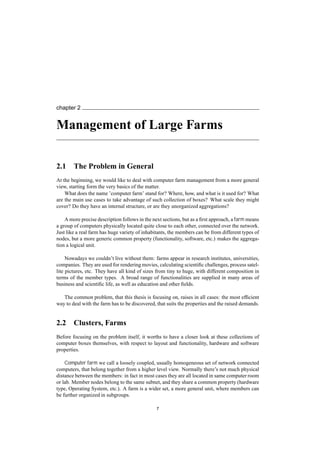
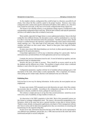
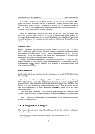
![Existing Solutions for Farm Management Automatic OS Installation for Individual Machines
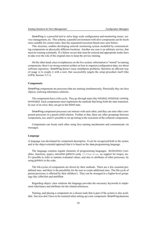
NODE
Install options file
Install Directory
SERVER
pull
mount, HTTP, FTP
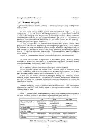
Figure 3.1: Install Method used by KickStart, JumpStart, YaST
3.2.2 JumpStart
A short allusion to Solaris’ JumpStart ([JS]) can be found here. The concepts followed by Kick-
Start are very similar to what this tool uses.
There are two stages in a JumpStart setup.
In the first one an application called Sysidtool takes control. This registers information (time
zone, system locale, nameserver, etc.) which can be entered interactively, or can come from a
config file (sysidcfg).
The second stage is the system configuration (disk partitioning, parameter definitions, pack-
ages). The information needed here are in files called profiles.
Though these files have a different syntax from the one for ks.cfg, just as command names
are different for JumpStart form KickStart, in principal the main characteristics of the two tools
are the same. A shared directory is available on the network, from where configuration profiles
can be derived, together with additional data necessary for the process.
Incomplete JumpStart specification also results in interactive requests for parameters. This
means that partially pre-configured interactive installations are possible.
A variance to KickStart is that the JumpStart server needs the exact specification of the
clients in /etc/hosts and /etc/ethers, which means that it needs to know certain parame-
ters in advance, while with KickStart clients were arbitrary and hidden (apart from specification
in NFS allow-list).
Furthermore, there are two additional differences, that are worth mentioning.
A main, so called rules file is located on the JumpStart server, which expresses correspon-
dence between clients and profiles that drive their install. This is determined for sets of nodes
grouped by common properties (architecture for instance). The same rules file can be utilized
along the whole cluster, and it will help to assign the right profiles to each of these groups.
These files introduce a higher level organization unit in the farm configuration than individ-
ual boxes. Assigning appropriate setups for distinct groups and clusters is possible, supporting
suitable configuration according to a farm’s internal structure.
Another interesting feature is the script, that needs to be run after each modification on the
profiles, in order to validate their syntax.
29](https://image.slidesharecdn.com/83c99311-30f8-47bf-a9c9-26add8d8a990-150503123653-conversion-gate02/85/thesis-2005-029-29-320.jpg)
![Existing Solutions for Farm Management Automatic OS Installation for Individual Machines
3.2.3 FAI
The next tool to focus on is closely related to the previous ones. The name is FAI ([FAI]), which
stands for Fully Automatic Installation. FAI is specific to the Debian Linux operating system.
Despite very similar functionality, the concepts differ from the previously discussed RedHat
solution. After the (network or floppy) boot, a remote filesystem, residing on the install server
for this purpose is mounted on the nodes as the root file system via NFS [NFS] services. After-
wards, the installation script starts execution, getting options from a special directory structure
accessible also by the NFS-mount, or from a CVS ([CVS]) repository, that could be local or
remote.
To be able to handle different configurations, FAI introduced the concept of classes, attached
to each other by an inheritance-like relation. Nodes belong at least to one of these, by having a
list of containing classes in an increasing priority, in order to address the problem of overriding
declarations, when there are multiple anchors. Knowing their class identity , nodes will be able
to retrieve all corresponding scripts and packages from the strictly structured remote directory
they have mounted.
Having a brief look at the contents of this directory gives us a hint about how the system
works.
- The class directory holds scripts, that define environment variables needed later by
the configuration actions (invoked by executables from the scripts directory discussed
soon), and modules to be loaded for a class. Declarations can be performed both directly
and indirectly, where the latter means to include already existing class definitions.
- disk_config and package_config directories hold partition information and package
lists.
- Interesting is the idea introduced by directory scripts. Here instructions files for various
command interpreters (perl, bash, even cfengine 1) can be found, organized in directories
referring to the class they are created for. These are executed after all packages are
installed.
- Another smart solution, represented by the hook directory, gives the possibility to execute
scripts as an "intermission" between certain steps of installation. The install procedure
continues where it was interrupted after the script execution is finished. This can be useful
for instance to detect hardware parameters, and dynamically generate values needed by
future steps.
- Last in the enumeration is the files directory. Here mostly configuration files are col-
lected for the classes, which have to be deployed on the members. Files are stored in a
directory structure that refers to their future location, while their name is specific to their
class.
Compared to KickStart, we see a new concept here. Instead of delivering one file and then
continue working mostly locally on the node, in FAI, contact with the installation server is
necessary all the time. Therefore, this is more sensitive on server failures and network errors,
though these are rare on local networks, where installs are usually performed
However these issues have to be considered when using FAI.
1cfengine will be discussed later
30](https://image.slidesharecdn.com/83c99311-30f8-47bf-a9c9-26add8d8a990-150503123653-conversion-gate02/85/thesis-2005-029-30-320.jpg)
![Existing Solutions for Farm Management Automatic OS Installation for Individual Machines
Though we are looking for a fully automated solution, it should be mentioned that there’s
no correspondence for KickStart’s semi-automatic procedure within FAI.
Configuration information in the FAI directory structure is much more complicated, spread
in many files. For the sysadmin, a higher level of understanding is required, than it was for the
single one ks.cfg file. But this is not a disadvantage of the design of the FAI system.
These two tools are addressing different areas of problems. While KickStart focuses more
on the individual install action, using the structure of classes in FAI takes into account higher-
level cluster management-problems. It places information in a well-structured order, enabling
multiple different cluster installations easily.
FAI is powerful, flexible and introduces new features to the ones we have already seen. Due
to the complex structure, the usage is more difficult, as many instructions have to be written in
scripts, that are already available as KickStart built-in commands and options. Using a minimal
set of KickStart commands might be more handy for less experienced admins, while the large
variety of options enable to perform specific, customized KickStart setups, as well.
On the other hand the way how FAI is designed, it doesn’t depend on which options are
implemented and which are not: ’hooks’ can implement any actions, that could be done man-
ually between main install steps, ’scripts’ can do anything after installation, and it all can be
completed by arbitrary ’files’, that can be delivered and modified locally by the other facilities.
With FAI also various special steps can be defined, in case of less usual local parameters,
though this needs experience and knowledge about the system.
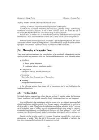
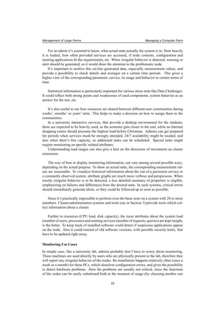
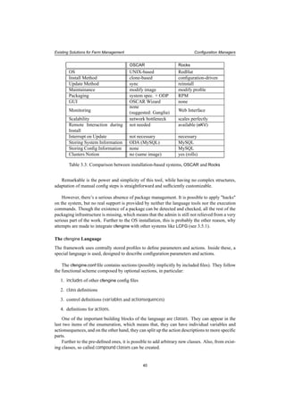
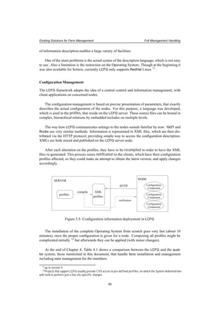
Install Directory NODE
SERVER
mount
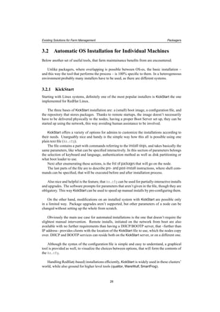
Figure 3.2: Sketch of the Installation Method used by FAI
3.2.4 YaST
More similar to RedHat KickStart is the method used by SuSE Linux. Based on the operating
system configuration tool YaST2 (Yet another System Tool 2. [YAST]), an installer called Au-
toYaST is used to organize the automatic installation method.
AutoYaST also has a main control file driving the procedure. This is in fact, is so similar
to the ks.cfg, that it’s even possible to generate it from this KickStart configuration file. Within
the YAsT2 control file XML ([XML]) is used for description. This doesn’t only give a general
interface to the different kinds of commands and parameters. XML is suitable for passing in-
formation stored in (configuration) variables (Section 2.4.2), and has a huge amount of parser
tools already available. This eases the work of the developers, who can simply use one of these.
The XML files will be transformed to YaST2 profiles after being delivered to the clients.
Since AutoYaST has a Graphical User Interface, the admin doesn’t need to edit the control
file manually; a full configuration can be put together by clicking on the right options.
31](https://image.slidesharecdn.com/83c99311-30f8-47bf-a9c9-26add8d8a990-150503123653-conversion-gate02/85/thesis-2005-029-31-320.jpg)
![Existing Solutions for Farm Management Higher Level Installation
3.3.1 OSCAR
The first to be discussed is OSCAR, the Open Source Cluster Application Resources toolkit
([OSC]).
The reason for starting with this one is the way how the system is put together by applica-
tions that solve separate subtasks of the remote farm installation. This layout of components
shows the different functional parts of the system very well.
OSCAR is the first development project supported by informal society Open Cluster Group
(OCG, [OCG]). Unfortunately it supports only RedHat and Mandrake Linux, but Debian also
appears on some of these components’ future plans.
Building bricks of this framework are the System Installation Suite (SIS, [SIS]), the Clus-
ter Command and Control (C3) and the OSCAR Password Installer and User Management
(OPIUM). Furthermore the OSCAR Database (ODA) and the OSCAR Package Downloader
(OPD) play an important role in package management.
These all together form a nice solution for a clone-based installation. 2
The opportunity of maintaining the running system definitely lifts OSCAR over plain cloning
software. Packages can be installed on actually working nodes easy and fast. During this action,
the saved "golden image" is treated the same way as the real nodes are, in the sense that update
is applied on the image as well. This means that neither redistribution of the modified image is
necessary, nor software installation on the members nodes one by one. Thanks to the OSCAR
Database that maintains the package information, the update of more differently-shaped images
can be also handled.
To provide easier usage, OSCAR adds a Graphical User Interface hiding lower-level appli-
cations, command-line tools. The GUI covers all actions that these tools enable; this makes
cluster management easy and fast.
System Installation Suite (SIS)
SIS itself is an individual project developed by contributors from various institutes 3. It’s de-
signed to be an tool, that works on various Linux distributions. Having the tasks split up, the
three main areas could be handled by different groups of developers.
Sub-projects that came to existence this way are:
1. SystemImager ([SI1])
2. System Installer ([SI2])
3. System Configurator ([SI3])
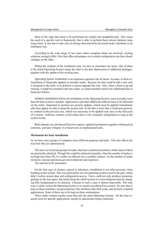
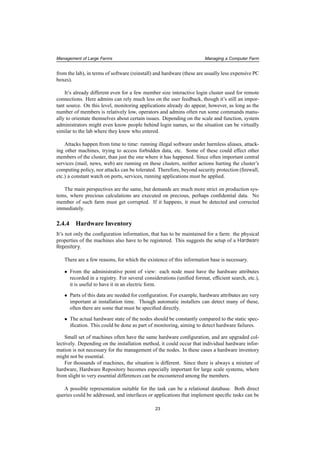
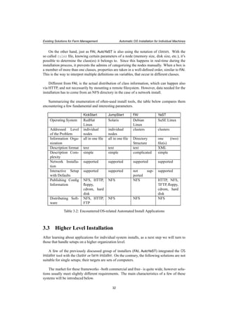
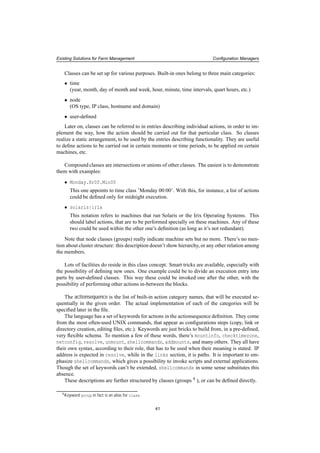
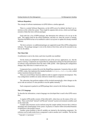
Figure 3.3 is a diagram on how these three subsystems interact.
SystemImager captures a hard disk image of an existing machine. This is typically a "golden
client" representing the ideal setup of all nodes, which has to be deployed on all of them. Sys-
temImager has a command for updating an already installed image on the client in a way that
2There are many other cloning applications, which are not discussed here in more detail. A few examples: Patagonia
CloneSys [CLS], Dolly [DOL] (developed for fast switched networks), Norton Ghost from Symantec, ImageCast from
Innovative Software Ltd., DriveImagePro form PowerQuest, etc.
3IBM Linux Technology Center, Hewlett Packard
33](https://image.slidesharecdn.com/83c99311-30f8-47bf-a9c9-26add8d8a990-150503123653-conversion-gate02/85/thesis-2005-029-33-320.jpg)
![Existing Solutions for Farm Management Higher Level Installation
image
system desciption
"golden client"
System Imager
System Installer
System Imager
System Configurator
SERVER
NODE
create
create
configure
update
Figure 3.3: Sketch of SiS Installation used in OSCAR
the whole image doesn’t have to be pushed through the network again: it’s only the modified
parts that the node contents are synchronized with.
System Installer realizes another possibility for image creation. Given a file describing par-
titions and an RPM list, the tool builds the image on the installation server. This can be very
handy when cloning multiple images, which doesn’t have to be manually installed on different
"golden client" nodes.
System Configurator performs a few essential node-specific steps following the installation
(network setup, etc.) New systems can immediately get the necessary parameters over the static
image copied on the hard disk.
These facilities offer two solutions for the image maintainance. The first is performed
directly on the "golden client". This can be favorable when changes have to be investigated,
they should be tested before deployed, so whenever the admin needs to see how a system is
running with the new settings, software, etc. When there’s no doubt about the success of the
operations, the already-existing image can be used as a live filesystem on which the new settings
can be applied directly and the resulted image can be deployed onto the clients.
Cluster Command and Control toolsuite (C3)
Having the image prepared, the next step is to use the Cluster Command and Control toolsuite
([C3]). C3 is developed at Oak Ridge National Laboratory as a separate project.
This tool is a set of commands, that operate on the whole cluster or a part of it. It has several
commands with various functions. Just a part of them are mentioned here.
There is one (cexec), that implements parallel command execution over the cluster mem-
bers. Another one (cpush) realizes data distribution (directories, files) to each node. Using
the synchronization mechanism, data transfer can be restricted to what is really necessary; un-
changed parts of the filesystem don’t have to be transmitted through the network. This is a
serious gain, e.g. when 40 GB disk images need to be only partially updated on several mem-
ber nodes. For disk image distribution a separate command (cpushimage) exists in C3. Other
34](https://image.slidesharecdn.com/83c99311-30f8-47bf-a9c9-26add8d8a990-150503123653-conversion-gate02/85/thesis-2005-029-34-320.jpg)
![Existing Solutions for Farm Management Higher Level Installation
instructions (cget, crm) are getting and removing specified files.
C3 doesn’t only have an important role in the installation and update, but provides com-
mands that form the base for OPIUM, the OSCAR accounting management also.
Cluster administration, package management
There are two other components, which finally, fully belong to the OSCAR toolsuite. In fact,
they extend the OSCAR functionality more to the direction of cluster management, than cloning
tools.
OSCAR uses a packaging mechanism, with packages similar to RPMs. The OSCAR Database
(ODA), rooted in MySQL, is the component that keeps track of node software contents. It has
administrative functionality in terms of cluster information as well.
A command-line interface hides the physical database, providing an easy way to access
information and to execute package operations. The OSCAR Package Downloader (OPD) is
the application that obtains the packages.
3.3.2 Rocks
One of the most widespread systems is definitely NPACI Rocks ([RCK]). This toolsuite is espe-
cially popular in the United States, but from the approximately 280 Rocks clusters 4 many are
from other parts of the world.
Rocks is based on RedHat Linux, but it has its own distribution of the Operating System in-
cluded. This contains the base system, RedHat updates, NPACI packages, and other additional
packages. Unfortunately the fact that there’s no support for other Operating Systems is a strong
limitation of the otherwise rather efficient system.
The major concept of this freely downloadable framework is to make the farm setup and
maintainance as easy as possible.
Main characteristics
Within system procedures, the strongest emphasis is on the node installation. Setup from
scratch is not more than a simple command, and it takes about 10 minutes to be finished.
The process is driven by configuration data in contrast to the previously mentioned disk-
image-delivering mechanisms. Necessary information is ordered in uniform directories, that
represent higher-level abstraction on the relationships between the elements.
The setup procedure is elaborated in detail. Even a remote interaction is possible with the
client during the install, using application eKV, designed for this purpose.
The description-driven approach together with the list of packages enables configuration
changes and software updates to be deployed by the framework. However, the update proce-
dure instead of changing anything on the already working node simply reinstalls it with the new
parameters, as if it was a brand-new setup.
4The list can be found at http://www.rocksclusters.org/rocks-register
35](https://image.slidesharecdn.com/83c99311-30f8-47bf-a9c9-26add8d8a990-150503123653-conversion-gate02/85/thesis-2005-029-35-320.jpg)
![Existing Solutions for Farm Management Higher Level Installation
Settings of a node are not traced further after the initial steps are done, administrators have
no knowledge about the actual state of the farm members. Alerts are triggered by the monitoring
system (Ganglia, [GL]) when failures occur. Rocks doesn’t have a configuration information
management system; differences from original parameters are not followed up at all.
The install procedure is reliable and fast. This explains why the system doesn’t emphasize
on following the configuration state of the nodes. A safe way to clean up any misconfiguration
that occurred is to set it up from scratch.
The same approach is reflected on the way how configuration and software updates are im-
plemented.
Though having an update procedure labels the framework to be a configuration tool as well,
the strong emphasis on the installation procedure keeps Rocks more an installation framework.
What Rocks is suitable for
There’s a strong relation between a farm’s structure and functions, and the applied management
tools. Admins have to consider several parameters, main characteristics and requirements in
order to be able to make the right decision about what to be used.
Rocks is a delicate solution in particular for huge, basically homogeneous, perhaps com-
mercial purpose clusters, where changing old to brand-new both in terms of soft- and hardware
is rather preferred, than spending time on with following up and fixing problems.
In these cases neither the physical box itself, nor the contained software are precious. These
nodes normally don’t hold user data. Home directories – if there are any – are stored on network
filesystems (like AFS) instead, on stable and reliable nodes, that are not meant to be often
manipulated.
These, perhaps High Availability Clusters have such importance, that minutes of downtime
can be charged in serious financial damage. No time to lose: substitution for a corrupted node
must be back and running the soonest possible, or being completely replaced otherwise. It
isn’t worth to investigate on details of failures. Member nodes here are usually much the same,
mostly cheap commodity hardware.
With such conditions, there’s no point to pay more attention on the running system’s cur-
rent state of configuration either. It’s irrelevant as long as nodes don’t fail and they provide
demanded functionality. If something goes wrong, the monitoring system detects it soon, and
notification will be generated.
With a slightly different motivation, similar things can be said about utilizations in educa-
tional institutes. Interactive student labs need frequent complete reinstalls, and no configuration
management. For this kind of maintainance, Rocks is a rather suitable solution. Probably that’s
why, the base of the Rocks-community are universities.
On the other hand, lack of information and control over running system’s parameters is not
acceptable on certain other cluster types.
As an example we should consider the case, when applying an urgent security patch on a
huge, strongly loaded batch system, which is constantly executing short and long running jobs.
Such action requires a scheduled downtime after draining the queues, or detecting one by one,
when a node is "empty", and then perform the update (reinstall) on it, which is hard to carry out.
(Probably the most convenient solution might be a way between the two: perform the procedure
on subsets of the cluster.)
36](https://image.slidesharecdn.com/83c99311-30f8-47bf-a9c9-26add8d8a990-150503123653-conversion-gate02/85/thesis-2005-029-36-320.jpg)
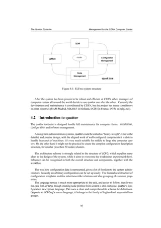
![Existing Solutions for Farm Management Configuration Managers
profiles
XMLMySQL
profiles
node
specific
info
KickStart
config
file
NODE
Kickstart
SERVER
graph
Figure 3.4: Rocks installation structure
3.4.1 cfengine
The name ([CFE]) comes from A Configuration Engine which perfectly describes the tool’s
functionality. cfengine doesn’t do OS installation, but operates on an already working system.
cfengine is developed for UNIX-based systems, (though, invoked from special environment
it can be available for others as well) 8
. The idea is to take over the duty of a UNIX system
administrator. When customizing software, adjusting system, service, application parameters
several tasks occur from time to time: file manipulation (edit, copy, etc.) , creating directories,
changing filesystem access permissions, executing (self-written) scripts, etc.
That’s exactly what cfengine is designed for: taking over these tasks, performing them in a
structured way, without restricting the freedom the admin had when doing the work manually.
At the same time, it gives the possibility to have a higher-level view of the farm, much easier
to see through, plan with, change fundamentally or modify slightly, as it was true for the nodes
one by one.
To describe information the introduced syntax is clear and easy to follow. Most keywords
are coming from the UNIX-world, which makes it easy to learn and understand for one, who
has at least a little experience with such.
Opposite to the model of component hierarchy and relations seen recently, this one comes
up with another way of thinking. A different schema with different grouping and execution
path concepts appears here. If the previous systems could correspond to object-oriented pro-
gramming, this one would be again a representative of procedural languages.
The sequential concept is a bit similar to what was found for the KickStart installer, but
while there each group need their own control files, here one file can hold all variants, thanks to
the richness of the language. Of course, having one enormous config file is not what an admin
wants for a large farm: such a configuration should be split up to logical units, that will build
up config structure by being included.
8On a Windows using cygwin application, that enables a Unix-like environment
39](https://image.slidesharecdn.com/83c99311-30f8-47bf-a9c9-26add8d8a990-150503123653-conversion-gate02/85/thesis-2005-029-39-320.jpg)
![Existing Solutions for Farm Management Configuration Managers
Different action entries require different syntax elements, that can describe the actual task.
These follow the UNIX commands that carry out the same function. Also, the language has
built-in functions to make the utilizations of often-used operations easier, and it also has several
ways to issue commands directly to the shell.
All these facilities make it possible to realize any setup layout and perform checks, without
a restriction on the order or type of the steps.
The Setup and Commands
There are a few commands that realize cfengine actions on the client and the sever side.
In order to install the actual configuration settings, the command cfengine has to run on
the client with the appropriate cfengine.conf file. It also could be invoked periodically by a
cron job.
The update command doesn’t need root access, therefore a user without admin rights can
run it to fix configuration errors.
On the server file permissions, directories have to be adjusted on the basis of hosts and
domains. The command cfrun can notify clients to rerun the cfengine command, for which
depending on the configuration they might want to download the newest config file version.
The server doesn’t publish (push) the file, it can be only downloaded (pull) by the clients.
The original setup uses a NFS-mounted directory which holds the cfagent.conf and its
included files (if any), together with those config files, that need to be copied to the nodes (pos-
sibly to be modified afterwards). This is not a large amount of data, therefore it could be copied
over the network to the boxes, without involving data accessed on NFS.
Only cfagent.conf is needed for the config process. All kind of operations (further down-
loads etc.) can be achieved using this one.
Security
A security infrastructure, using public-private key pairs is integrated, so the nodes authenticate
themselves to the server, and also the other way around.
There are two reasons to emphasize about security is the cfengine framework. On one hand,
to prevent a non-authorized node to access the configuration information. On the other hand, a
faked server shouldn’t be able to offer the cfagent.conf file to the clients.
3.4.2 SmartFrog
To show a very different approach to the configuration task, we continue with SmartFrog, the
Smart Framework for Distributed Groups ([SF]). The tool comes from UK, Bristol, from the
HP labs exactly.
The framework is more than a configuration tool: basically it creates an environment for
distributed programming. As for such, Java ([JAVA]) is used, which is also strongly present in
the language, developed for SmartFrog component description. This relation also manifests in
the inheritance-based approach.
42](https://image.slidesharecdn.com/83c99311-30f8-47bf-a9c9-26add8d8a990-150503123653-conversion-gate02/85/thesis-2005-029-42-320.jpg)
![Existing Solutions for Farm Management Configuration Managers
take care of created and terminated instances, while the registry still remains up-to-date.
External commands like scripts can also be invoked from the component code.
Security
Practically it is easy to join the system, therefore security issues need to be considered. The
framework’s security model uses so called trusted groups, where members have the right to
distribute SmartFrog resources.
cfengine SmartFrog
OS UNIX-based
(in principal)
RedHat
Windows
Architecture central control
sequential execution
distributed system
parallel execution
System Characteris-
tics
system config suite with
automatized sysadmin tasks
distributed programming
environment
Info Location central arbitrary
Update Process one command component life-cycle
Language based on UNIX commands based on Java
Component Rela-
tions
none as in Object-Oriented Lan-
guages
Monitoring for "neighbor" nodes built-in component monitor-
ing
GUI none avail. in plug-in
(SmartFrog Eclipse)
Table 3.4: Comparison of the Configuration Systems cfengine and SmartFrog
Above Table 3.4 shows a summary of the properties of the discussed configuration manage-
ment systems.
3.5 Full Management Handling
In the encountered evolution of farm management tools, the last one are the systems, that deal
both with installation, and the management of software on the nodes.
3.5.1 LCFG
The first representative, LCFG 10 ([LCFG]) was developed by the Computer Science Depart-
ment of Edinburgh University. It was used by the European Data GRID project ([EDG]), as the
officially supported solution for the complete, automatized installation of service and worker
nodes on the local fabric.
LCFG realizes a full solution for node installation and management for RedHat Linux sys-
tems. The architecture is well-designed, consists of subcomponents that realize different func-
tionalities. Deployment of information and package management are practical. The basic idea
10We mostly refer to version LCFGng
44](https://image.slidesharecdn.com/83c99311-30f8-47bf-a9c9-26add8d8a990-150503123653-conversion-gate02/85/thesis-2005-029-44-320.jpg)
![Existing Solutions for Farm Management Full Management Handling
variables can’t be shared is a possible source of duplication and inconsistency inside the system.
Source files can be included in each other. This increases complexity, but also defines a cer-
tain hierarchy among the sources, and enables to split variable definitions in a sensible structure.
A very interesting and useful feature introduced by one of the accessory libraries is the
template substitution. It is useful when generating configuration files with a complex structure.
Defining templates, it’s possible to modify only the relevant parts of the file, and the rest is
retrieved from the template. Inside the components library functions are used, to drive the
completion of the template file.
Templates belong to the same RPM package as the component that uses them.
Performance
The system is very efficient especially when used for large farms. Increasing the number of
nodes does not effect the time needed for the LCFG installation . Approximately 10 minutes
are necessary to set up a node from scratch.
However, scalability issues might raise in the profile compilation, as fundamental changes
are performed that affect many of the nodes.
Also, network access to the Software Repository might be a bottleneck, as all clients initiate
file transfers to download RPMs specified on their RPM lists.
Interesting measurement results about scalability tests on LCFG-based installations can be
found in [LCFGperf].
Integration with other tools
There are investigations on how to obtain more powerful management tools, by creating hybrid
systems as combinations of the existing ones, in order to unite their advantages.
The latter two, SmartFrog and LCFG were integrated successfully ([SFLCFG]) together re-
sulting in a more efficient system, as they are individually. This way a fully automatized farm
management framework can be presented, where dynamic decisions can be taken.
Since SmartFrog doesn’t solve the problem of installation, LCFG can be used for the au-
tomatic setup procedure, including the setup of the SmartFrog software itself. Afterwards,
SmartFrog components can take control over LCFG components following policy rules defined
on the LCFG server, considering run-time parameters.
A use case for such setup could be a cluster, where a crashed server has to be replaced with
the most appropriate member of a well-defined set, taking into account their actual state (current
load, etc.). SmartFrog components are perfect for the task of choosing the best candidate. They
can also invoke the relevant LCFG component, that will call methods like starting the crashed
machine’s services or registration with the new server.
47](https://image.slidesharecdn.com/83c99311-30f8-47bf-a9c9-26add8d8a990-150503123653-conversion-gate02/85/thesis-2005-029-47-320.jpg)

![chapter 4
The Quattor Toolsuite
We have already discussed and compared several of the currently existing solutions for automa-
tized farm management. In this chapter the focus is on one particular implementation, spending
more time on a deeper analysis.
The name of this tool is quattor, which stands for Quattor is an Administration Toolkit
for Optimizing Resources. In principal, it was developed at CERN, as a part of the European
DataGrid project ([EDG]), aiming to fulfill the Configuration Management and Installation
Management and Maintainance requirements, in the scope of EDG Work Package 4 ([WP4]) –
the Fabric Management Work Package within the DataGRID project.
4.1 Management for the CERN Computer Center
For the CERN Computer Center, administration is organized by ELFms the Extremely Large
Fabric management system ([ELFms]) .
ELFms has to realize a high-level, production quality system, scalable in number of nodes,
that’s expected to raise as the Computer Center gets extended in the preparation for the opening
of the Large Hadron Collider ([LHC]). One of the main design objectives is to adopt heteroge-
neous hardware as well as homogeneous, and to be able to deal with nodes that have different
functionalities (disk servers, batch/interactive nodes, etc.).
This is achieved by the interopability of three subsystems within the ELFms project: Lemon,
the LHC EDG Monitoring ([LEM]) LEAF, the LHC-Era Automated Fabric toolset and the quat-
tor toolsuite. (See also Section 5.1.1)
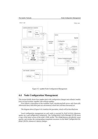
The structure of the ELFms system is shown on Figure 4.1
The quattor framework brought a radical change in the CERN Computer Center manage-
ment. After the successful test runs, it rapidly took over the task of installation, and the role
of SUE 1 , the previously used configuration tool. Actions that took hours or days, now can be
brought to effect in a few minutes without having services stopped, etc.
More and more nodes got installed and configured by quattor. Currently the 95% of all
Linux nodes in the CERN Computer Center are installed and managed by this framework,
while an increasing number of tape servers are also getting migrated to use it.
1(Standard UNIX Environment [SUE])
49](https://image.slidesharecdn.com/83c99311-30f8-47bf-a9c9-26add8d8a990-150503123653-conversion-gate02/85/thesis-2005-029-49-320.jpg)
![The Quattor Toolsuite Concepts, Architecture Design
[...]
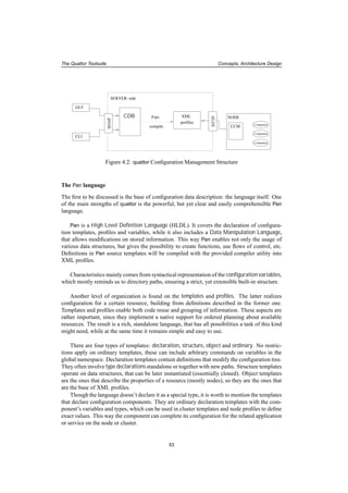
"/hardware/cpus" = list( create( cpu_intel_p3_800 ),
create( cpu_intel_p3_800 ) );
Which will result in path
"/hardware/cpus/0/vendor" = "Intel"
"/hardware/cpus/0/model" = "Pentium III (Coppermine)";
"/hardware/cpus/0/speed" = 796.550;
"/hardware/cpus/1/vendor" = "Intel"
"/hardware/cpus/1/model" = "Pentium III (Coppermine)";
"/hardware/cpus/1/speed" = 796.550;
The language has several built-in functions, and it also enables the definition of others, that
can similarly perform dynamical actions both on the configuration tree, and on the right-hand
side of variable assignments.
Pre-defined functions implement various categories of actions. There are functions to ma-
nipulate data and the configuration tree schema, as create, delete, clone. Tests operations
are available both for general queries (like exists, is_defined), and specific to types, data
structures (is_boolean, is_list, is_array, etc.). Furthermore, supported data structures are
supplied with discovery and modification procedures and operators.
This current set is already enough for regular setups, however special, sophisticated user-
defined functions can be created for individual cases. Functions can dynamically detect actual
configuration parameters, and perform actions accordingly. They can not only access the con-
figuration tree, but define their own local variables. Pan supports the three basic flows of
control: command sequences, if-then-else structures and loops. These can be used within the
functions, and this can realize from simple to rather complicated tasks.
More information about Pan can be found in the Pan Language Specification ([PAN]).
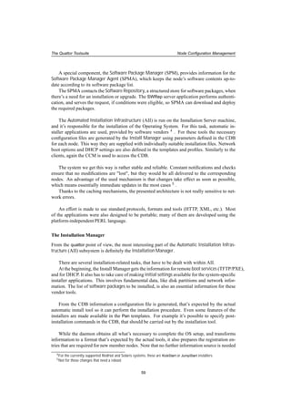
The Configuration Database
CDB is the location of Pan source templates and profiles. In contrast to the name, this storage
is not a database in the regular sense: similar to CVS ([CVS]) it’s designed to hold plain text
files written in Pan, the configuration language for quattor.
CDB has to store all data necessary from the bases of the Operating System install leading
through the fully functional configuration to the periodic updates of the running box. Therefore
CDB information is complex and heterogeneous, describing various groups of parameters.
Hardware parameters (CPU, memory, cards, etc.) is collected here, in order to provide
what’s necessary for the automatic installer (KickStart). 2 Also later on, there can be special
applications that need to know hardware attributes. In fact, for the OS installation additional
definitions are also needed: partition table, network, language, time settings, etc. These reside
in the database as well. One other important field that has to be covered in the CDB templates
is software contents of the nodes: package lists, that enumerate what has to be installed on the
machine, with parameters that are needed and will be applied by the configuration components.
From a higher-level point of view, it’s also important to record cluster topology, and roles
of members in the database, too.
2The concept of CDB is to store configuration information, therefore only the part of hardware information should
be kept there, that is needed for this purpose.
55](https://image.slidesharecdn.com/83c99311-30f8-47bf-a9c9-26add8d8a990-150503123653-conversion-gate02/85/thesis-2005-029-55-320.jpg)
![The Quattor Toolsuite Concepts, Architecture Design
By containing all configuration data, CDB stores a desired state of the machines both in
terms of software and hardware. This can be used by monitoring facilities to detect if the nodes
got in an irregular state.
CDB provides a common interface for accessing the data. It realizes a virtual data store,
where actions are implemented on transactions bases handled within the scope of user sessions.
3 System managers, who will need to edit templates and profiles, must have an account and
password set up, to be able to interact with the database. Access is provided via the SOAP
([SOAP]) protocol.
In the CDB, the authentic source of configuration data, incorrect information can not be
present, therefore syntax and semantics check must be run against new or modified Pan tem-
plates and profiles, before they could enter the system.
The syntax is verified, when the file is uploaded to the CDB, but at this point the file contents
are not a part of the stored information yet. Validation happens when a finalizing commit
command is sent from the user. Exactly as it happened in LCFG, profiles have to be recompiled
each time, when there was a modification.
A node’s XML profile comes to existence compiling the corresponding object template and
all its included files. All concerned templates and profiles are revised to detect possible incon-
sistency, and after the semantical check new XML profiles will be generated, which contain the
latest modifications.
The resulting profile is transformed to XML and published on the web, while an UDP noti-
fication is sent to the client to notify about the change.
The underlying CVS system ensures versioning and backups for each verified state of the
Pan sources. This also enables a possibility to return to previous versions.
CDB and Pan together are excellent to represent and store configuration data. The only
drawback is a problem with the scalability: the more templates are there the longer the compi-
lation takes for fundamental changes, that effect many profiles.
The Configuration Cache Manager
The Configuration Cache Manager (CCM) has the task of storing locally on the machines the
latest version of the corresponding XML profile.
CCM is particularly important, since it reduces the network dependency, as it turns all
profile-related operations to local actions. Whenever a configuration component is invoked, it
only has to access a file on the local filesystem, instead of contacting a remote server. Therefore
off-line operations can be supported, and also configuration operations will have a significantly
shorter execution time. This method also takes load off the server.
When a new XML profile is created for a node, it gets a notification, which signals the CCM
to get the new file. Also, in order to keep consistency between data on the server and the clients,
the CCM periodically checks, if the stored profile is up-to-date, and downloads the latest one,
if it outdated.
This operation can be enforced manually as well by the system administrator.
3A clear correspondence is can be discovered with CVS, the back-end system in CDB.
56](https://image.slidesharecdn.com/83c99311-30f8-47bf-a9c9-26add8d8a990-150503123653-conversion-gate02/85/thesis-2005-029-56-320.jpg)
![The Quattor Toolsuite Node Configuration Management
for this operation than what is in the CDB, which means that the central database achieved its
goal.
Currently the Install Manager for RedHat-based systems is the Anaconda Installer ([ANAC]),
which allows plug-ins for Solaris and other Linux distributions (SuSE, Debian) as well.
cdispd and the Node Configuration Deployer
When a node gets a new profile, it has to adjust its current configuration settings according to
the new attributes. This is done in several steps, where the cdispd service and the Node Con-
figuration Deployer (NCD) have the key role.
cdispd continually queries the Configuration Cache Manager CCM, if a new profile should
be downloaded. When a modifications is noticed, it determines which components are con-
cerned by the changed variables. 6
When the affected components are known, the NCD has to be invoked, taking as a parameter
this list of components. NCD is realized as a command-line application (ncm-ncd) and it acts a
front-end to execute the components. As such, it can be invoked both manually (by the admins)
and non-interactively (via cron or cdispd).
Configuration Components
Configuration Components are the plug-in modules of the framework, that perform actions on
client-side.
The concept of components was already introduced in SUE 7, the configuration system used
at CERN before quattor. This provided a general format and interface to each individual item
that takes care of an application’s or service’s parameters, options. No load is generated on the
server, as all actions can be performed locally after the node’s profile is there.
In the Pan configuration tree, there’s a branch labelled "/software/components". This
subtree is further structured by component names. Under these paths, each component has its
specific variables, which can be arranged in complex structures.
Bringing new namespace in the tree, all components must have a declaration template in
the CDB, which includes (inherits from) type "component_type". This ensures that each com-
ponent will have a boolean variable indicating if the component is active in an actual context.
This must be set true for the nodes, where the component should be available for execution. 8
In the component’s declaration template, arbitrary new types can be defined, that might be
used to declare variables, subtrees, and other declaration templates can be included here as well.
All the component’s variables e.g. those that have the form
"/software/components/<component_name>/<variable_name>"
must be declared in the component’s Pan template.
6There is a clear correspondence between variables and container configuration components, since a variable’s name
(the "full path"), includes the component’s name after the leading "/software/components/" prefix.
7Unix Workstation Support ([SUE])
8The fact that the component is installed on a node doesn’t imply that it can be invoked: it can’t be executed only if
the node’s profile doesn’t mark it being active.
60](https://image.slidesharecdn.com/83c99311-30f8-47bf-a9c9-26add8d8a990-150503123653-conversion-gate02/85/thesis-2005-029-60-320.jpg)
![The Quattor Toolsuite Node Configuration Management
Components themselves are essentially PERL modules, with a few obligatory include li-
braries and classes to inherit from. They must have at least one main function (called Configure),
that describes the configuration actions. This is the subroutine that will be executed by the NCD.
Additional functions are provided in the Node View Access (NVA) API library 9 , that gives
access to the configuration tree. Using function calls, queries can be issued to the CCM about
configuration variables of the node. It is possible to get the values of the variables and to tra-
verse the data structures.
The rest of the component source is regular PERL code. Facilities enabled by PERL can be
utilized: services can be restarted, whenever config changes require that, environment variables
can be accessed, files can be modified, etc. Though there are no restrictions, a few guidelines
exist that should be kept in mind when developing quattor components. More information can
be found in Section 5.2.1 and the NCM component writer’s guidelines ([CGL])
Components are deployed as packages, just as other software, and they are stored in the
Software Repository. However, there are certain regulations about what must be in a com-
ponent’s package in addition to the information that is required by the packaging mechanism
specification. For example in an RPM package, further to the obligatory, customized specfile,
there must be also a README file, a PERL documentation file (.pod) and the Pan templates that
declare the component in the CDB Global Schema.
A tool for component creation exists already, which eases the developer’s task by creating
initial samples for the obligatory files. These contain specific options that need to be changed
by the developer.
Having all these facilities, components are easy to create and deploy. As a starting point,
one component called testcomponent exists, as a working example.
More information about components can be found in Section 5.2.
Additional libraries: the NVA API
The native access to configuration variables is one of the main achievements obtained by the
quattor system. Both the structure and the values defined in CDB are available within the con-
figuration component code by using the Node View Access (NVA) API.
The root of this PERL library is EDG::WP4::CCM. There are several modules that belong to
this namespace. They implement the necessary classes.
The most important is the CacheManager class, which provides access to the locally cached
part of the configuration tree: variables that apply to the actual machine.
The tree itself is realized in the class Configuration. An object instantiated from here is
available for each CacheManager instance 10. The pointer is initially at the root of the tree,
which can be traversed by the object methods.
The NVA API has notations used for discovering this graph, which are manifested in PERL
classes, accordingly named as Element, Resource, and Property.
9See corresponding subsection of the chapter
10In component code, the actual Configuration object is automatically passed to the Configure subroutine, when
the component is invoked by the NCD.
61](https://image.slidesharecdn.com/83c99311-30f8-47bf-a9c9-26add8d8a990-150503123653-conversion-gate02/85/thesis-2005-029-61-320.jpg)
![The Quattor Toolsuite Node Configuration Management
Properties are the leaves of the tree: variables that have exact values. Internal nodes in the
configuration tree are the resources. Element is a more general group, where these two belong
to.
Parts of the tree can be queried by specifying the path in question. Traversing an unknown
(sub)tree is also possible by "stepping" from one element (resource) to another.
Elements can be queried about their name, path and type. The type of a resource is the type
of the data structure associated to it (TABLE, LIST, etc.), while properties have built-in basic
types (BOOLEAN, STRING, LINK, etc.). It’s also possible to query if an element (path) exists, if
an element is a resource or a property, etc.
Resources provide methods to get associated values in the appropriate data structure. The
orientation of property class methods is to get the actual value, knowing the type it belongs to.
Following a short code example can be found, about how to obtain values from the config-
uration tree:
if ($config->elementExists("/software/components/<comp_name>")) {
my $node = $config->getElement("/software/components/<comp_name>");
while ( $node->hasNextElement() ) {
my $element = $node->getNextElement();
if ( $element->isProperty() ) {
my $name = $element->getName();
my $value = $element->getValue();
$env{$name} = $value;
}
}
}
For more information about the NVA API, see [NVA], and the pod documentation for the
mentioned PERL classes.
LCFG and quattor
Table 4.1 summarizes the differences between the two discussed systems that achieve full man-
agement of farms.
4.5 Summary
During the last two years, quattor proved to be a reliable system in the CERN Computer Center
management.
The system is characterized by precisely designed and carefully implemented architecture,
and it is very efficient on large production systems. Strict rules, well-defined structures, inter-
faces, methods realize an organized, nicely handleable, scalable system.
Being very suitable for High Performance Clusters, the interest about quattor is raising
among scientific institutes.
62](https://image.slidesharecdn.com/83c99311-30f8-47bf-a9c9-26add8d8a990-150503123653-conversion-gate02/85/thesis-2005-029-62-320.jpg)

![chapter 5
My work in relation to the quattor
system
CERN, one of the core developer centers of the quattor toolsuite offers a possibility for stu-
dents from member countries to join the institute for roughly a year, in order to get a technical
training related to their studies. I had the privilege to get such a position within the CERN
Information Technologies department, Fabric Infrastructure and Operations (FIO) group,
where the quattor toolsuite was developed, and it’s heavily used in production since 2003.
5.1 The Fabric Infrastructure and Operations Group
Main activities and structure
The CERN IT-FIO group has several duties to cover in the management of the local fabric and
related areas, as it is stated in the FIO mandate ([FIOMAND]):
- Operation of Linux-based services in the CERN Computer Center, in particular running
the CERN Public Interactive Service (lxplus) and the CERN Batch Services (lxbatch)
clusters.
- Integrate and maintain these services to become a part of the LHC CERN Grid (LCG,
[LCG]) environment
- development of a computer center revision system
- management of computer center services
- supervision for currently performing CERN Computer Center upgrade
In order to meet these demands, the approximately 50 members of the group are split into
three sections, each taking the referring part of the encountered tasks.
• The Data Services (DS) section deals with tape servers and robots, together with the
CERN Advanced STORage Manager (CASTOR, [CASTOR]) service and several disk
servers as well.
• The Fabric Services (FS) section has to manage the interactive and batch services (lxplus
and lxbatch), including the management of the LSF 1 batch system.
1Name stands for Load Sharing Facility
65](https://image.slidesharecdn.com/83c99311-30f8-47bf-a9c9-26add8d8a990-150503123653-conversion-gate02/85/thesis-2005-029-65-320.jpg)
![My work in relation to the quattor system Configuration Components
5.2 Configuration Components
First I had to learn about the system. A very good approach how one should get involved,
is to start writing configuration components. This was my first exercise, and it helped me to
understand a lot about quattor and the logic behind it.
5.2.1 Writing quattor Components
Before turning to the exact task itself, a short introduction to component code development is
necessary.
Components are purely PERL modules, that inherit from the NCM::Component class, and
implement a main Configure subroutine. In order to understand their function, it’s important
to see what and what are not the aims of these pieces of software.
In general there are no restrictions on the semantics of a component code, but there are
suggestions on how to build the modules in order to preserve system integrity and portability.
Precise description on this matter can be found in the NCM Component Writer’s Guidelines
([CGL]). Here we just briefly want to show the main objectives mentioned there.
In principal, components should keep contact with CDB on behalf of the service, applica-
tion, etc. they represent, in a sense to read corresponding variables from the local copy of the
node’s XML profile, and perform related actions, whenever it’s necessary. To enable access
to the encapsulated CDB information, the NVA API (See Section 4.4) can be used within the
component code.
In fact that’s all they should do, and no more. They are not supposed to start or stop ser-
vices, only restart them if a config change makes it necessary, they shouldn’t perform pre- or
post-installation functions for software packages, neither substitute cron jobs. They shouldn’t
modify environment variables, since it would be out of control if components override each
other’s changes. It’s no problem to change specific parts of system configuration files with API
calls designed for this purpose, but one component shouldn’t re-generate profiles that might be
modified also by others.
Many components operate on one specific configuration file, not touched by any others.
Generating one like this is accepted, even supported with a template library, in order to avoid
uselessly hard-coding a complex syntax in the component sources.
There are suggestions on naming as well, to reflect functionality, related application, etc.
Components should not contain hard-coded site-specific information, but they must remain
portable between different computing environments and supported Operating Systems.
5.2.2 Components for the CERN Computer Center
Currently used components came to existence from two sources. Many of them are the "quattor
implementations" of modules from other systems, while other components fulfill newly raised
demands.
Migrating from the previously used SUE configuration system at CERN, quattor compo-
nents had to be created one by one, that would take over the role each of the old SUE ’features’.
Also, the LCG software installation and configuration performed with LCFG had to be in-
tegrated with the tools used in the CERN Computer Center, therefore LCFG components had to
67](https://image.slidesharecdn.com/83c99311-30f8-47bf-a9c9-26add8d8a990-150503123653-conversion-gate02/85/thesis-2005-029-67-320.jpg)
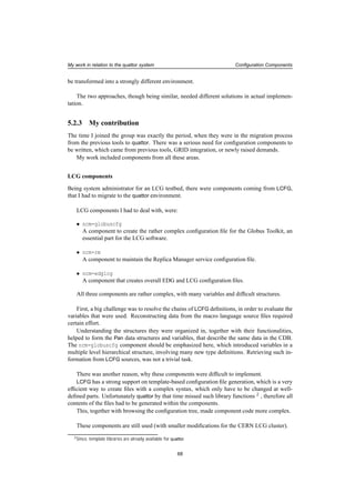
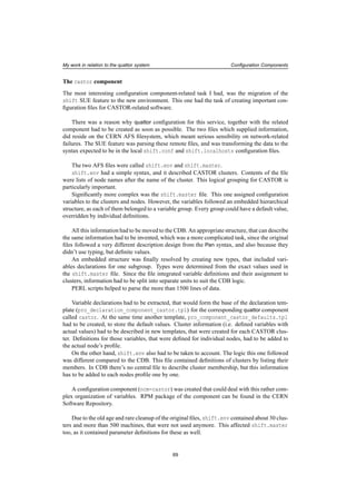
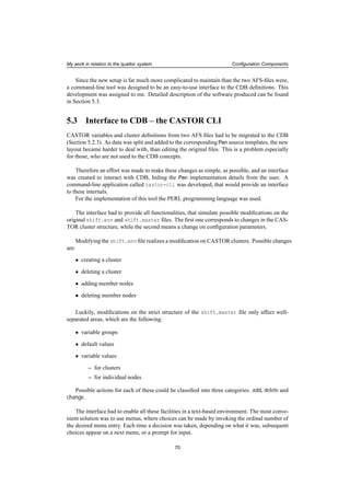
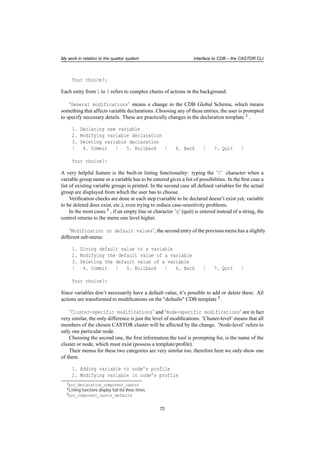
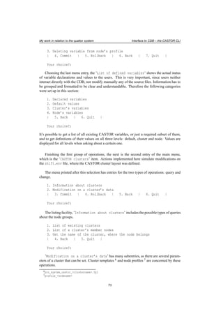
![My work in relation to the quattor system Interface to CDB – the CASTOR CLI
1. Create new cluster
2. Delete cluster
3. Modify stager name
4. Modify stager alias name
5. Add nodes to the cluster
6. Remove nodes from the cluster
| 7. Commit | 8. Rollback | 9. Back | 10. Quit |
Your choice?:
Further to cluster name, members, etc., there’s an additional, CASTOR-specific attribute,
which is the stager machine. This one has a sort of leading position within the group. This
attribute also can be modified.
Cluster creation and deletion involves the creation and removal of CBD templates.
Verification on entered data is done automatically (existing cluster can not be added, a mem-
ber can be defined for a cluster only once, etc.)
The interface realizes all what could be done on the original remote config files. The easy
way of making a decision (typing a single number) can be shortly acquired, which ensures a fast
and confident way of usage. This way, migrating configuration for the shift-files to CDB is
acceptable for those, who are not as comfortable with CDB usage, as they were with the direct
modifications.
Figure 5.1 presents the described usage.
5.4 Re-engineering the Software Repository code
Apparently, one of the most essential parts of the framework is the storage for software. The
Software Repository management tool, SWRep is responsible to maintain this ordered collec-
tion of packages.
Contents of the storage are organized into platform groups, which are further divided to
software areas. This is realized in a directory tree with the same structure (see the quattor-
ELFms Software Repository [QSW]). User access to these is based on Access Control Lists. In
order to provide a secure service, RSA authentication is used with public-private key pairs.
The tool consists of two parts: a server- and a client-side command-line application. User
commands are sent to the server, where corresponding ones are invoked and executed. There-
fore the client and the server applications are basically sharing a very similar command set.
However the server application is never used interactively, but always implicitly by the client-
side tool.
Querying and listing functions are available for the repository and other facilities for soft-
ware and user management, too. A brief list of mostly self-explaining commands shows the
main functionalities:
1. Software Repository structure maintainance:
• modifications:
– addplatform, rmplatform, addarea, rmarea,
74](https://image.slidesharecdn.com/83c99311-30f8-47bf-a9c9-26add8d8a990-150503123653-conversion-gate02/85/thesis-2005-029-74-320.jpg)
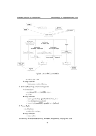
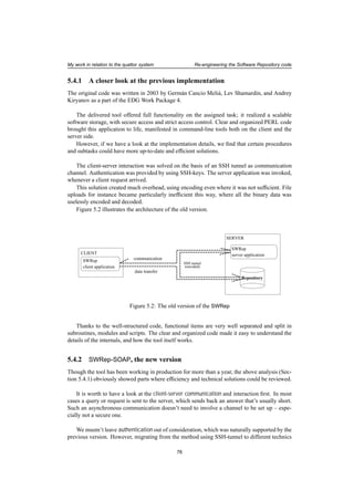
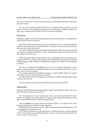
![My work in relation to the quattor system Re-engineering the Software Repository code
In order to set up the Digest authentication for the SWRep server service, the web server
configuration has to be changed. After restarting the web server, users can be added by using
the related utilities. A detailed description of the matter can be found in the installation instruc-
tions enclosed in the SWRep Server software.
Another authentication method available only for CERN users is also supported. This is
to use CERN NICE ([NICE]) usernames and passwords: the same as for the CERN Computer
Center’s CDB. To achieve this, the same libraries are used as in the CDB access tool (cdbop)
code.
Local file upload
The put function of the SWRep tool enables local file upload. This is a very useful facility,
therefore it must be included in the new code.
There’s a large number of file transfer tools and several different transfer methods. Which
one would be the most sufficient for the task, had to be investigated.
SOAP messages can include binary data as an ’attachment’. But this is only suitable for
small files, typically for pictures or documents. It’s definitely not the right approach for large
software packages.
File uploads are supported actions within CGI forms, but for the SWRep server tool this
feature can not be used. The problem is that the SWRep CGI interface is not a form, but a
proxy script.
What finally was found is a command-line application named curl. This implements data
transfer, both up- and downloads for Linux and several UNIX-based systems. curl works over
many protocols, including HTTP and HTTPS, which makes it perfectly suitable for the SWRep.
Therefore this became the chosen tool. Uploads are initiated from the client-side. The des-
tination file is created in the server-side directory that’s given in the client configuration 8 . In
order to avoid data corruption, the uploads first create a temporary file, which will become part
of the repository only in the case of a successful transfer. This also prevents failures caused by
parallel uploads for the same package.
Adopting curl made its installation a necessary prerequisite for the SWRep client applica-
tion.
The architecture of the new SWRep version is shown on Figure 5.3.
5.5 Summary
The year I spent as a member of the IT-FIO group developed my technical skills, as it gave an
opportunity to apply in practice what I’ve learned during my university studies. Being a part
of a team with experienced software developers and farm managers got me acquainted with
practical aspects of operational issues.
8It must be published by the managers of the repository, which is the area on the remote file system available for
uploads.
78](https://image.slidesharecdn.com/83c99311-30f8-47bf-a9c9-26add8d8a990-150503123653-conversion-gate02/85/thesis-2005-029-78-320.jpg)
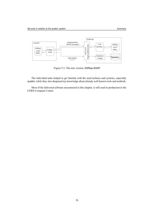

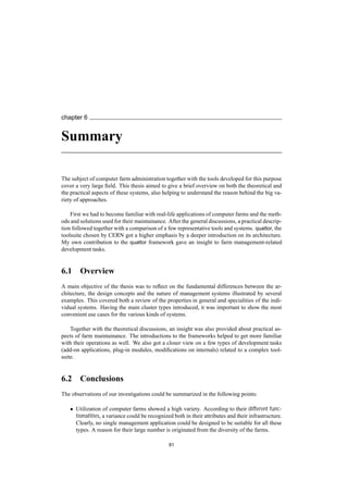

![Bibliography
[BEOWF] http://www.beowulf.org
[HPC] http://www.linuxhpc.org
[HPCintro] http://www.ac3.edu.au/hpc-intro/hpc-intro.html
[HAC] http://www.ieeetfcc.org/high-availability.html
[AFS] http://www.openafs.org
[PVM] http://www.csm.ornl.gov/pvm/pvm_home.html
[MPI] http://www-unix.mcs.anl.gov/mpi
[RPM] http://www.rpm.org
[DEB] http://www.debian.org/doc/FAQ/ch-pkg_basics.en.html
[GRID] http://www.gridcomputing.com
[Eb] http://etherboot.sourceforge.net
[FAI] http://etherboot.sourceforge.net
[ANAC] http://rhlinux.redhat.com/anaconda
[NFS] http://www.faqs.org/rfcs/rfc1094.html
[CVS] https://www.cvshome.org
[YAST] has to be searched, it’s not obvious
[JS] http://www.amorin.org/professional/jumpstart.php
[OSC] http://oscar.openclustergroup.org
[OCG] http://www.openclustergroup.org
[SIS] http://sisuite.org
[SI1] http://www.systemimager.org
[SI2] http://systeminstaller.sourceforge.net
[SI3] http://sisuite.org/systemconfig
[CLS] http://www.cs.inf.ethz.ch/CoPs/patagonia/clonesys/clonesys.html
85](https://image.slidesharecdn.com/83c99311-30f8-47bf-a9c9-26add8d8a990-150503123653-conversion-gate02/85/thesis-2005-029-85-320.jpg)
![Bibliography
[DOL] http://www.cs.inf.ethz.ch/CoPs/patagonia/dolly/dolly.0.57/dolly.html
[C3] http://www.csm.ornl.gov/torc/C3
[RPM1] http://rpmfind.net
[RCK] http://www.rocksclusters.org
[RL] http://www.rocksclusters.org/rocks-register
[GL] http://ganglia.sourceforge.net
[XML] http://www.xml.com
[CFE] http://www.cfengine.org/
[CYW] http://sources.redhat.com/cygwin/
[JAVA] http://java.sun.com
[SF] http://www.hpl.hp.com/research/smartfrog
[LCFG] http://www.lcfg.org
[LCFGperf] https://edms.cern.ch/file/384844/1/lcfg-scalab-test.pdf
[EDG] http://eu-datagrid.web.cern.ch/eu-datagrid
[SFLCFG] http://www.lcfg.org/doc/lisa03.pdf
[EDG] http://eu-datagrid.web.cern.ch/eu-datagrid
[WP4] http://cern.ch/hep-proj-grid-fabric
[LHC] http://lhc-new-homepage.web.cern.ch/lhc-new-homepage
[SUE] http://proj-sue.web.cern.ch/proj-sue
[ELFms] http://cern.ch/elfms
[LEM] http://cern.ch/lemon
[LF] http://cern.ch/leaf
[NVA] https://edms.cern.ch/document/440280
[SOAP] http://www.w3.org/TR/soap
[PAN] http://hep-proj-grid-fabric-config.web.cern.ch/hep-proj-grid-fabric-
config/documents/pan-spec.pdf
[CASTOR] http://castor.web.cern.ch/castor
[FIOMAND] http://it-div-fio.web.cern.ch/it-div-fio/mandate.html
[LCG] http://lcg.web.cern.ch/LCG
[CGL] https://edms.cern.ch/document/409650
[QSW] http://quattorsw.web.cern.ch/quattorsw
[NICE] http://winservices.web.cern.ch/Winservices
86](https://image.slidesharecdn.com/83c99311-30f8-47bf-a9c9-26add8d8a990-150503123653-conversion-gate02/85/thesis-2005-029-86-320.jpg)


This document discusses the management of large computer farms. It defines a computer farm as a group of networked computers located close together that are managed as a single logical unit, despite potential heterogeneity. Clusters are subgroups within a farm that are dedicated to a specific task. The document outlines some common applications of farms and clusters, including high performance computing, high availability computing, and small clusters for education. It then discusses the key aspects of managing large farms, including installation, configuration, monitoring, and hardware inventory. Existing solutions for automated farm management are also reviewed.