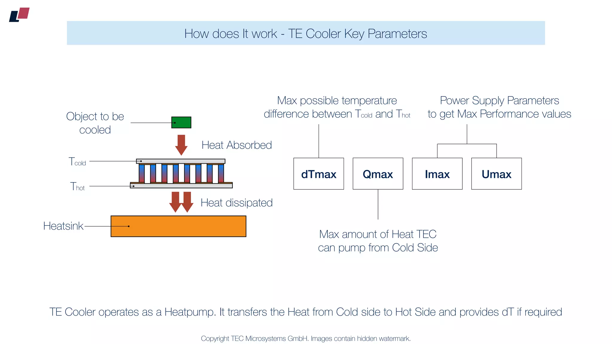
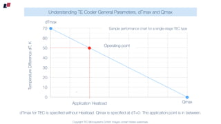
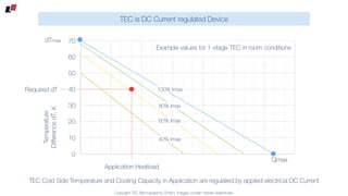
Copyright TEC Microsystems GmbH. Images contain hidden watermark.
How does It work - TE Cooler Key Parameters
TE Cooler operates as a Heatpump. It transfers the Heat from Cold side to Hot Side and provides dT if required
P
P
P
P
P
P P
Thot
Tcold
Heat Absorbed
Heatsink
Heat dissipated
Object to be
cooled
dTmax Qmax Imax Umax
Max possible temperature
difference between Tcold and Thot
Max amount of Heat TEC
can pump from Cold Side
Power Supply Parameters
to get Max Performance values
Copyright TEC Microsystems GmbH. Images contain hidden watermark.
Understanding TE Cooler General Parameters, dTmax and Qmax
0
10
20
30
40
50
60
70
Qmax
dTmax
TemperatureDifferencedT,K
0
Operating point
Application Heatload
dTmax for TEC is specified without Heatload. Qmax is specified at dT=0. The application point is in between.
Sample performance chart for a single-stage TEC type
Copyright TEC Microsystems GmbH. Images contain hidden watermark.
TEC is DC Current regulated Device
TEC Cold Side Temperature and Cooling Capacity in Application are regulated by applied electrical DC Current
0
10
20
30
40
50
60
70
Application Heatload
Required dT 100% Imax
80% Imax
60% Imax
40% Imax
Temperature
DifferencedT,K
Qmax
Example values for 1-stage TEC in room conditions
dTmax

Thermoelectric cooler key parameters

  • 1.
    Copyright TEC MicrosystemsGmbH. Images contain hidden watermark. How does It work - TE Cooler Key Parameters TE Cooler operates as a Heatpump. It transfers the Heat from Cold side to Hot Side and provides dT if required P P P P P P P Thot Tcold Heat Absorbed Heatsink Heat dissipated Object to be cooled dTmax Qmax Imax Umax Max possible temperature difference between Tcold and Thot Max amount of Heat TEC can pump from Cold Side Power Supply Parameters to get Max Performance values
  • 2.
    Copyright TEC MicrosystemsGmbH. Images contain hidden watermark. Understanding TE Cooler General Parameters, dTmax and Qmax 0 10 20 30 40 50 60 70 Qmax dTmax TemperatureDifferencedT,K 0 Operating point Application Heatload dTmax for TEC is specified without Heatload. Qmax is specified at dT=0. The application point is in between. Sample performance chart for a single-stage TEC type
  • 3.
    Copyright TEC MicrosystemsGmbH. Images contain hidden watermark. TEC is DC Current regulated Device TEC Cold Side Temperature and Cooling Capacity in Application are regulated by applied electrical DC Current 0 10 20 30 40 50 60 70 Application Heatload Required dT 100% Imax 80% Imax 60% Imax 40% Imax Temperature DifferencedT,K Qmax Example values for 1-stage TEC in room conditions dTmax