Download as PDF, PPTX
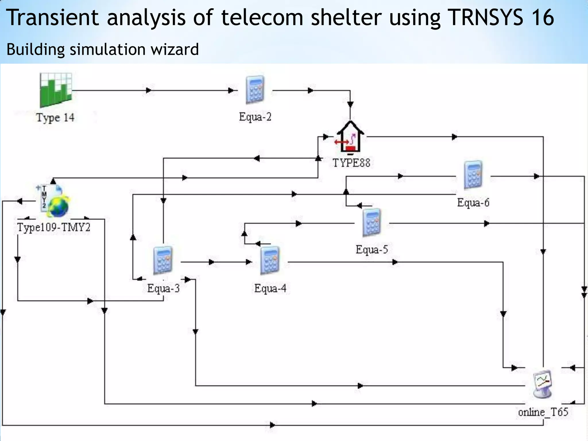
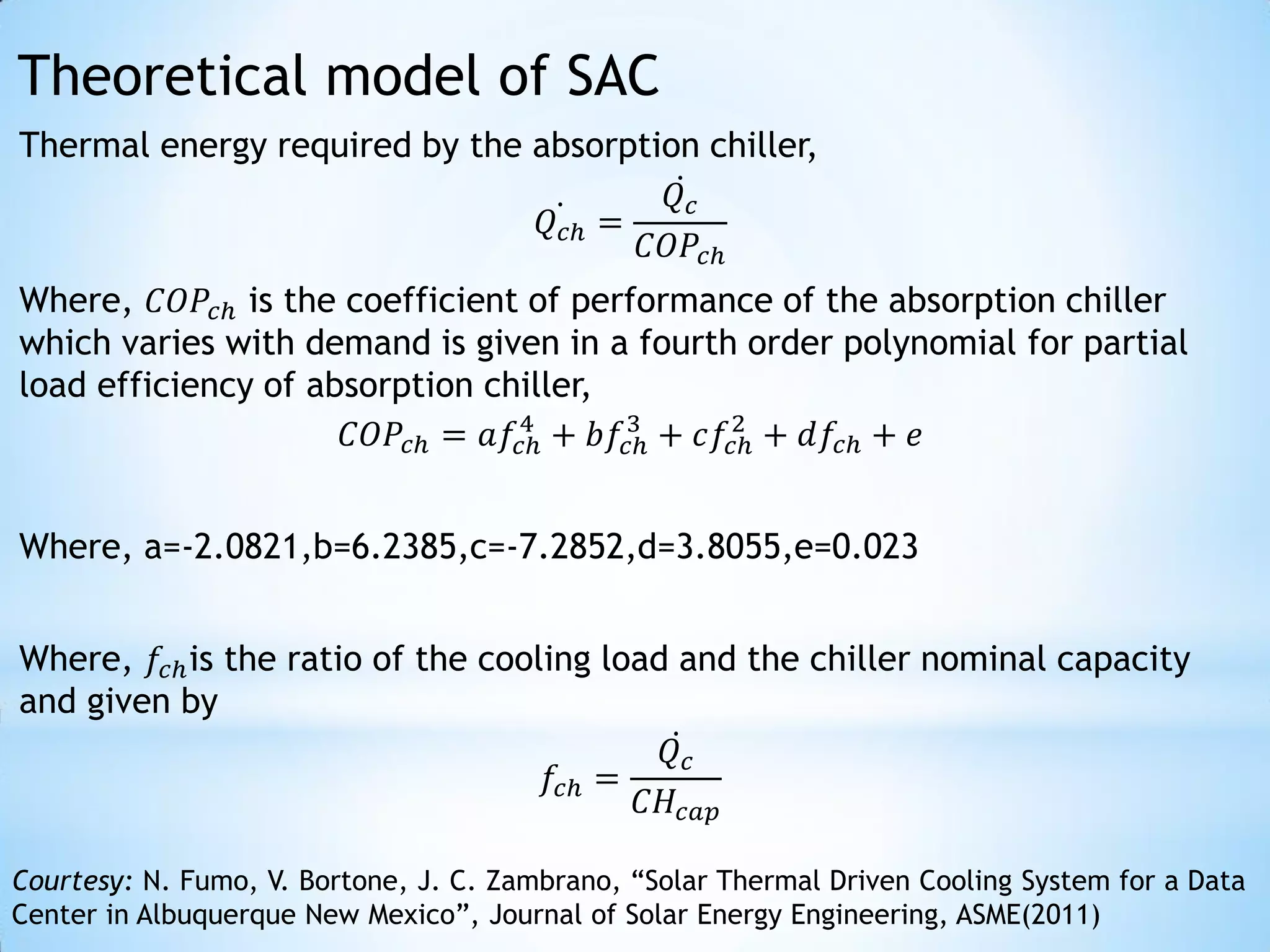

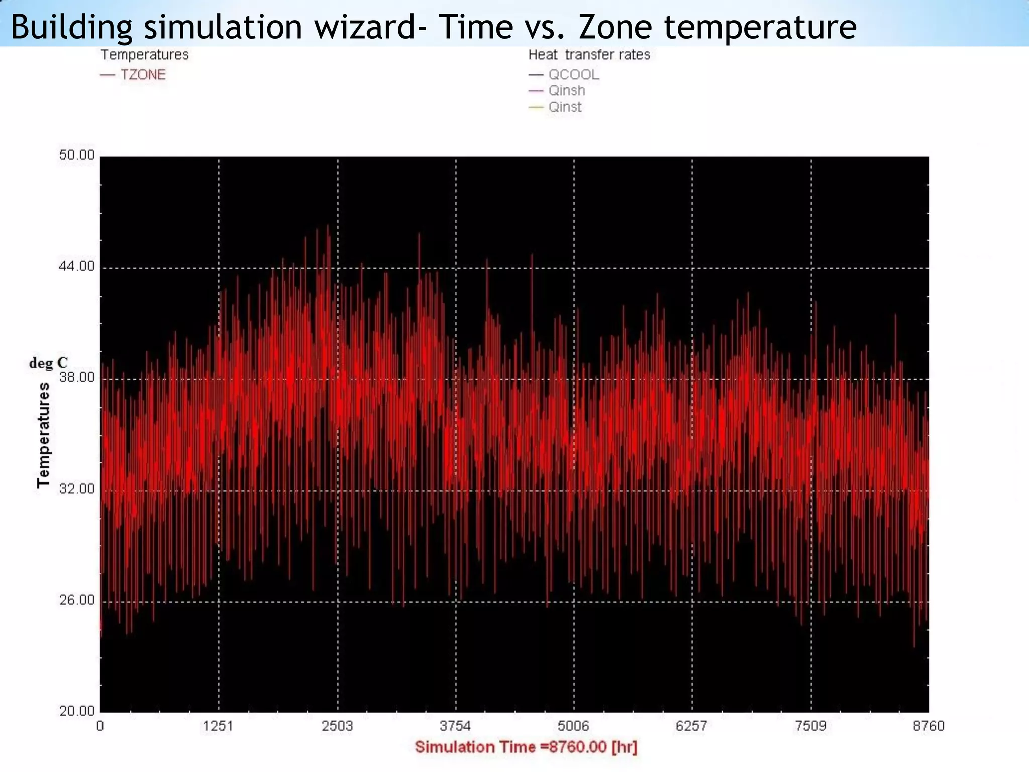
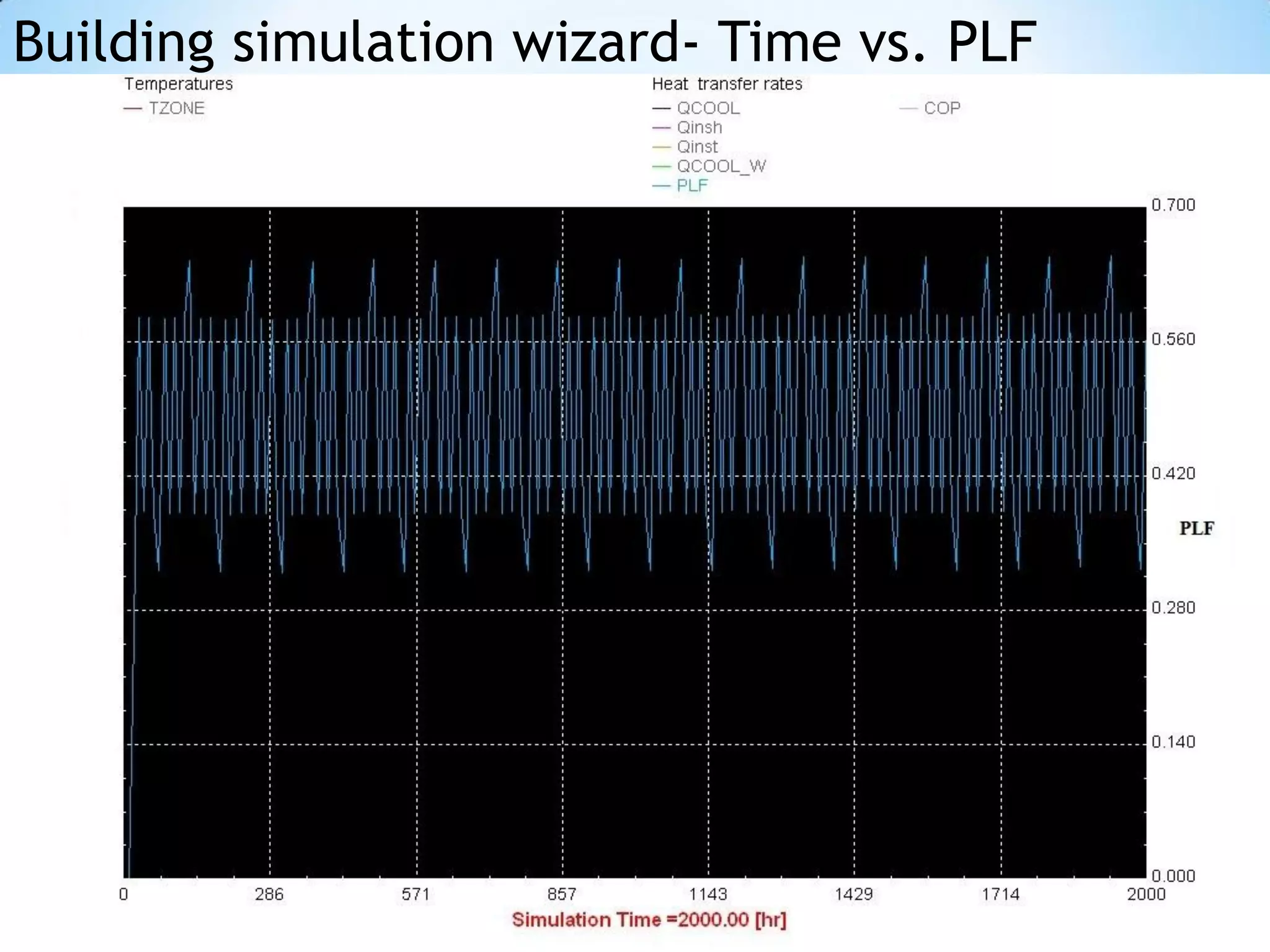
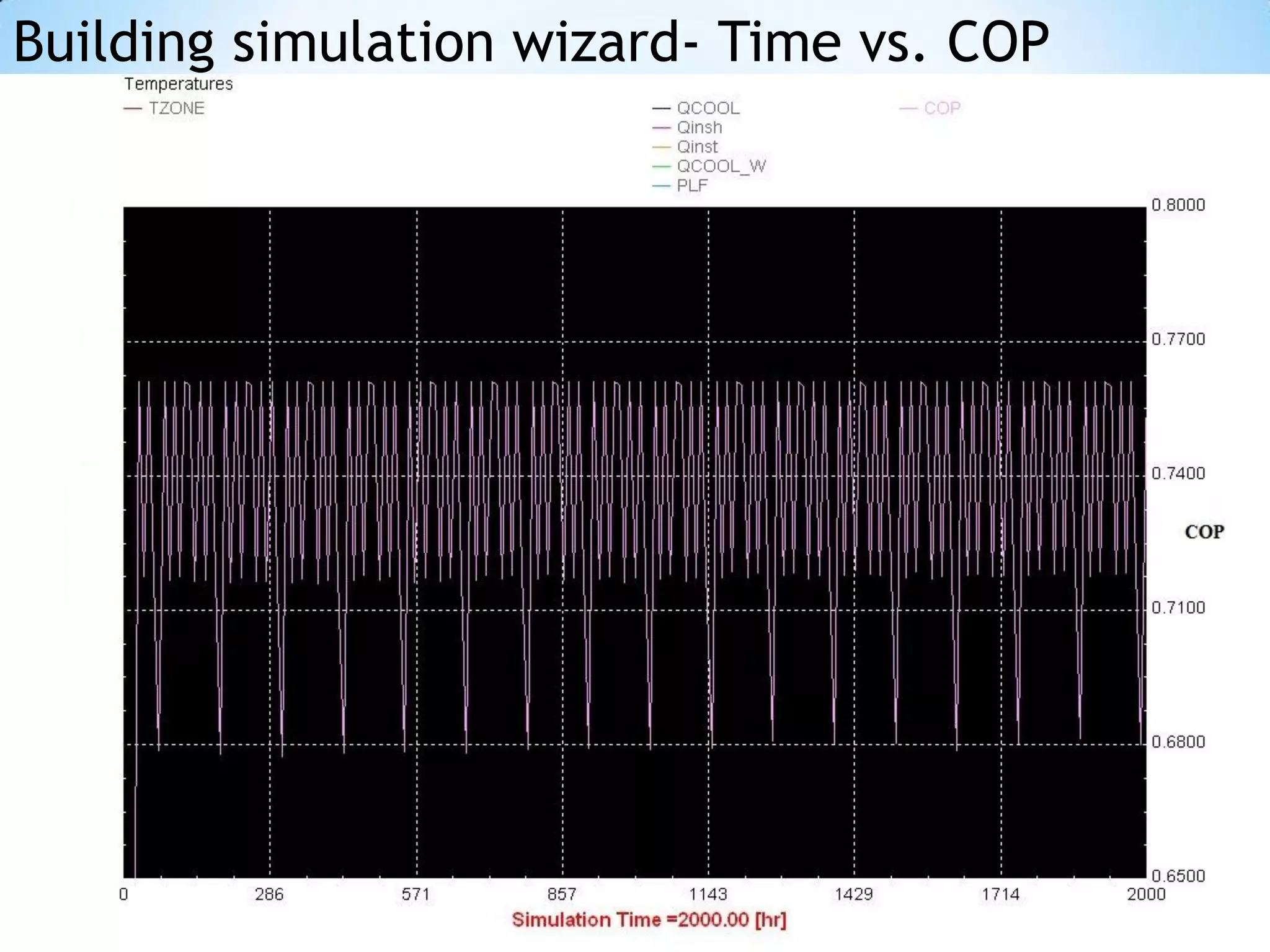
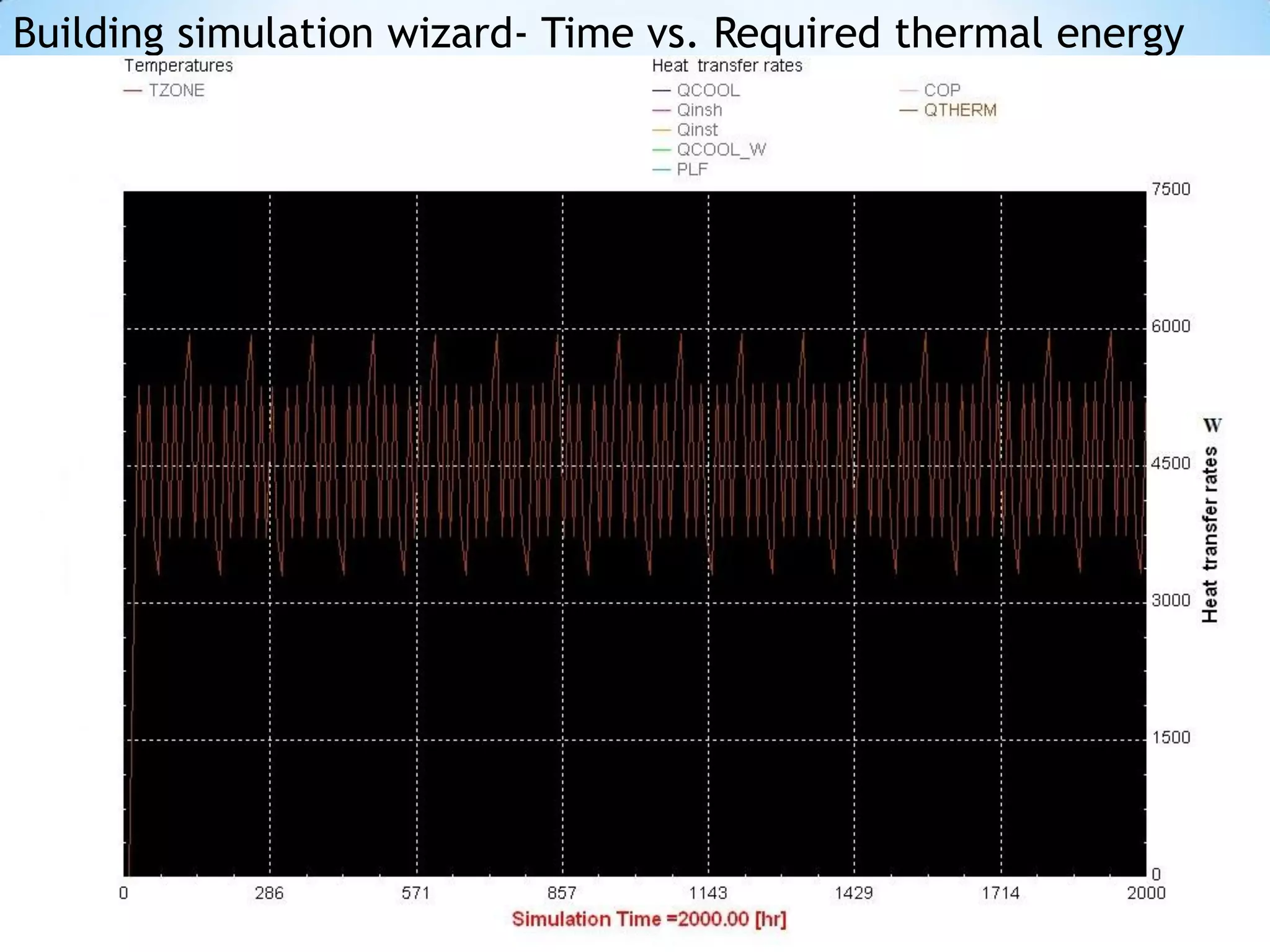
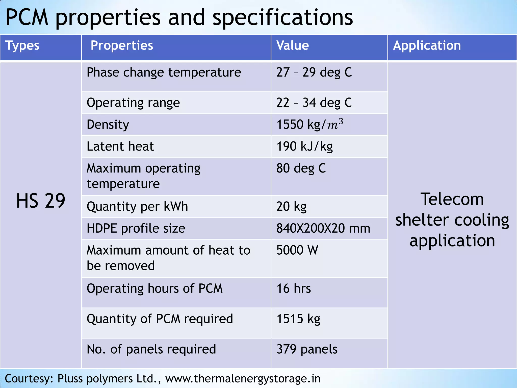
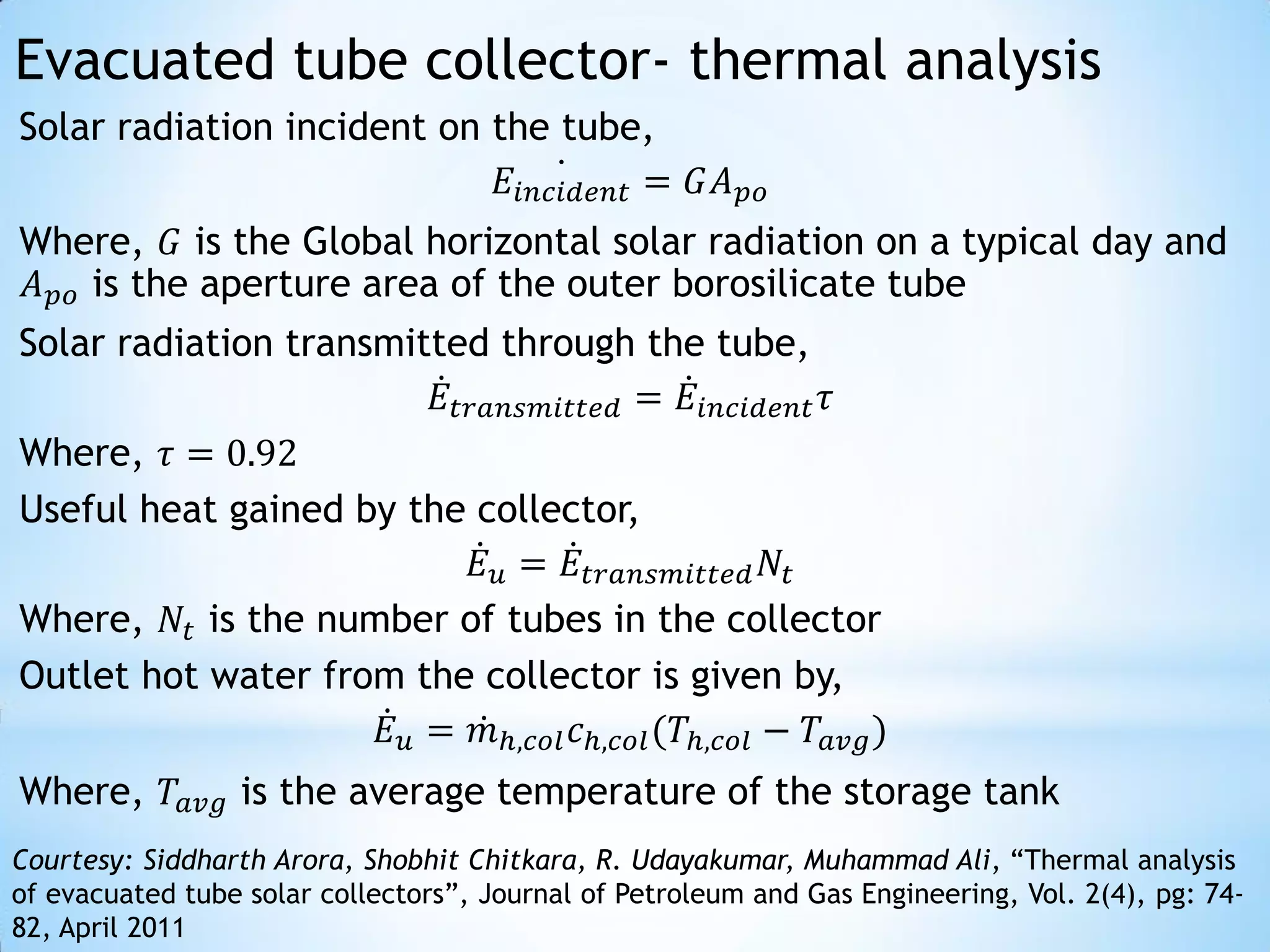
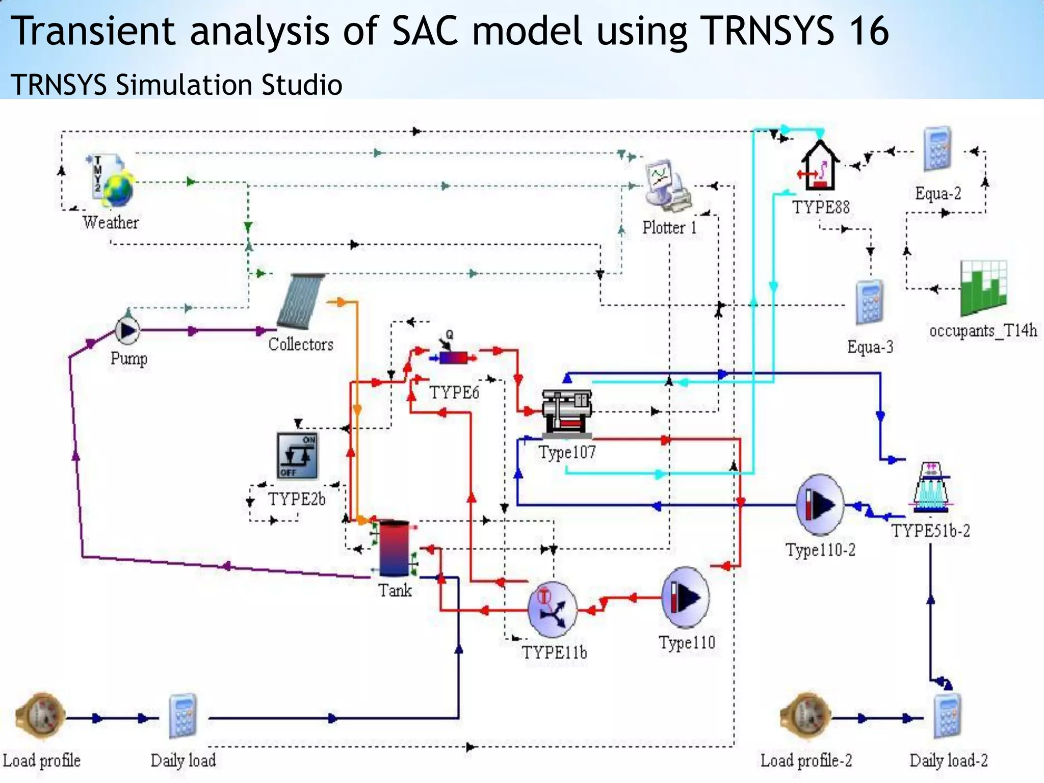
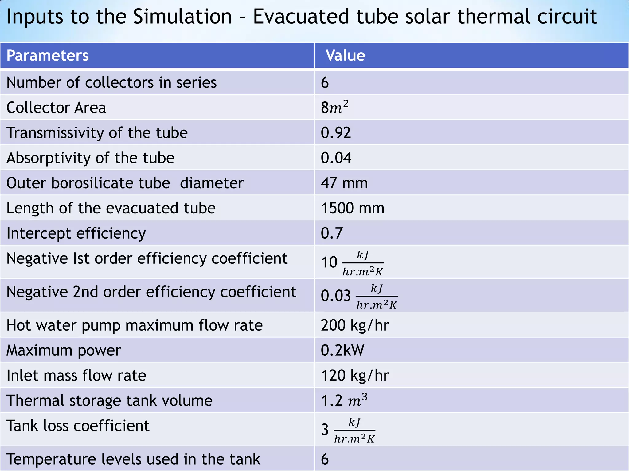
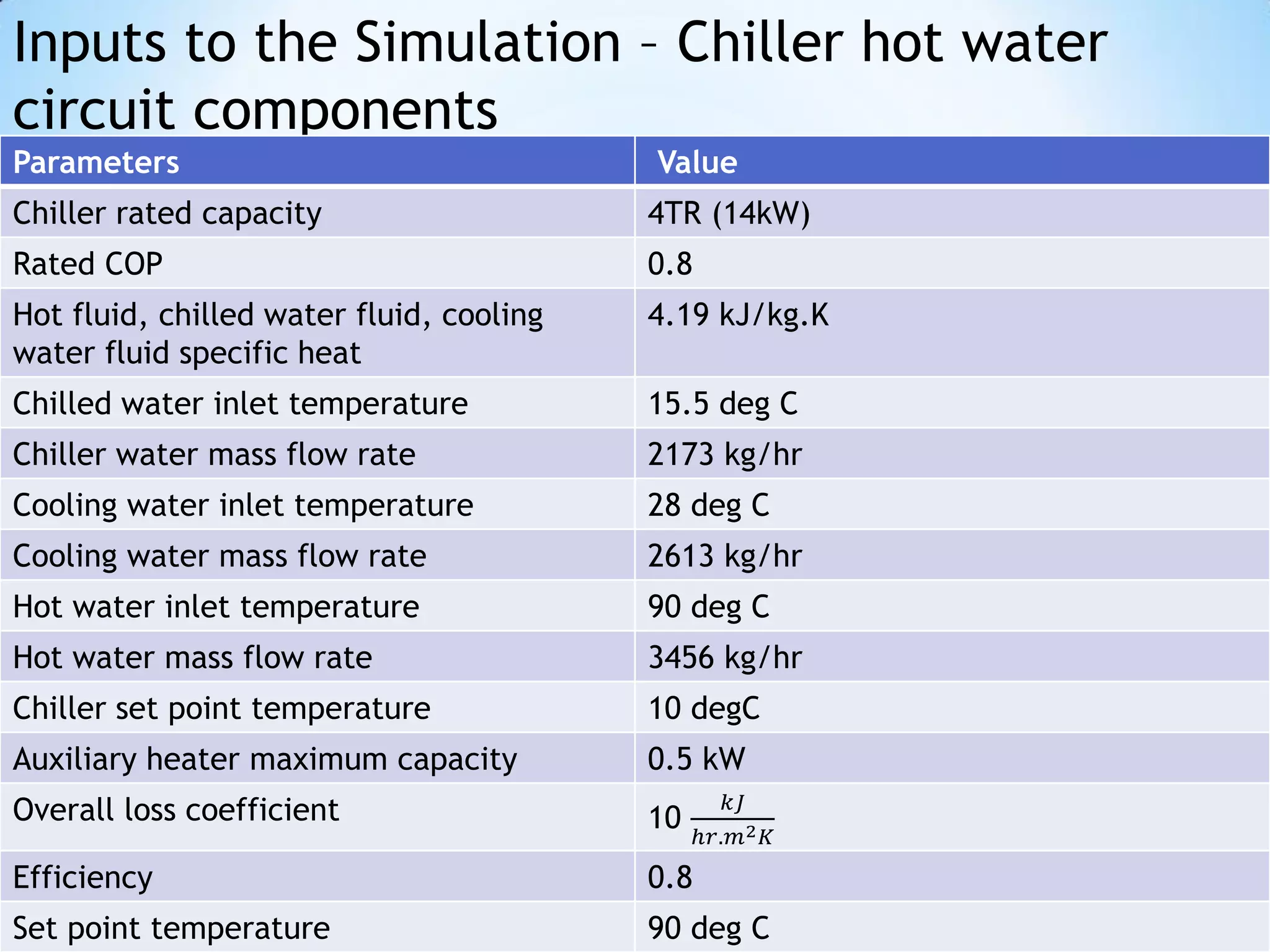
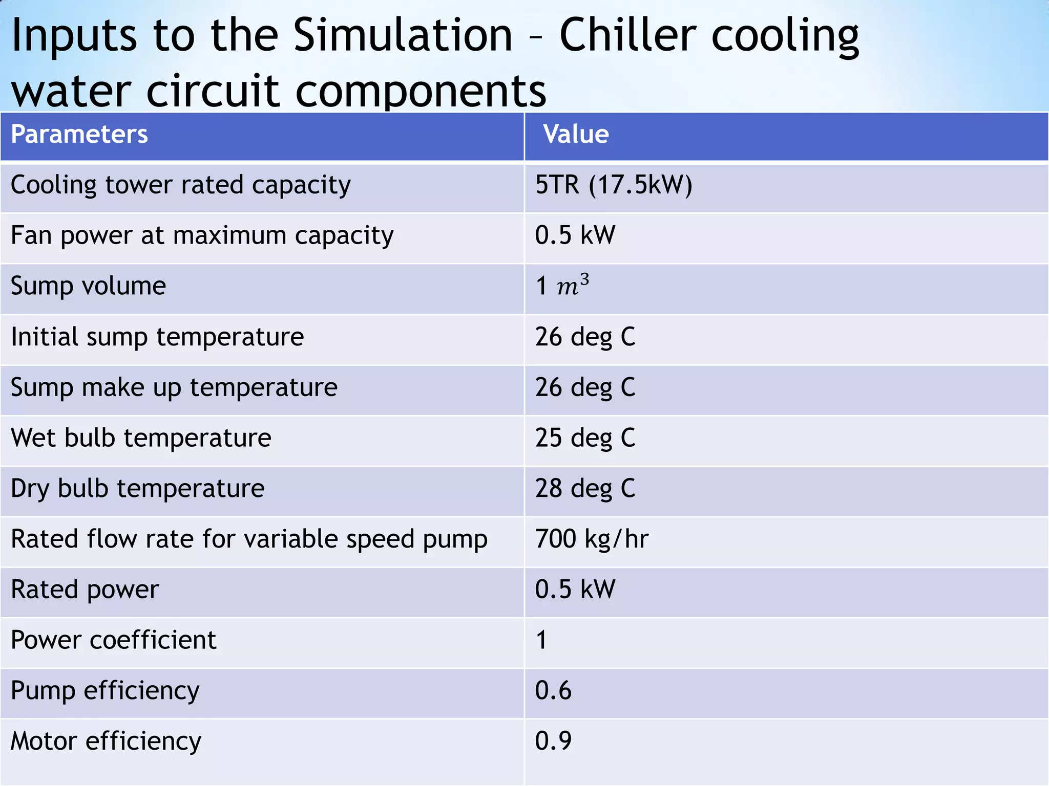
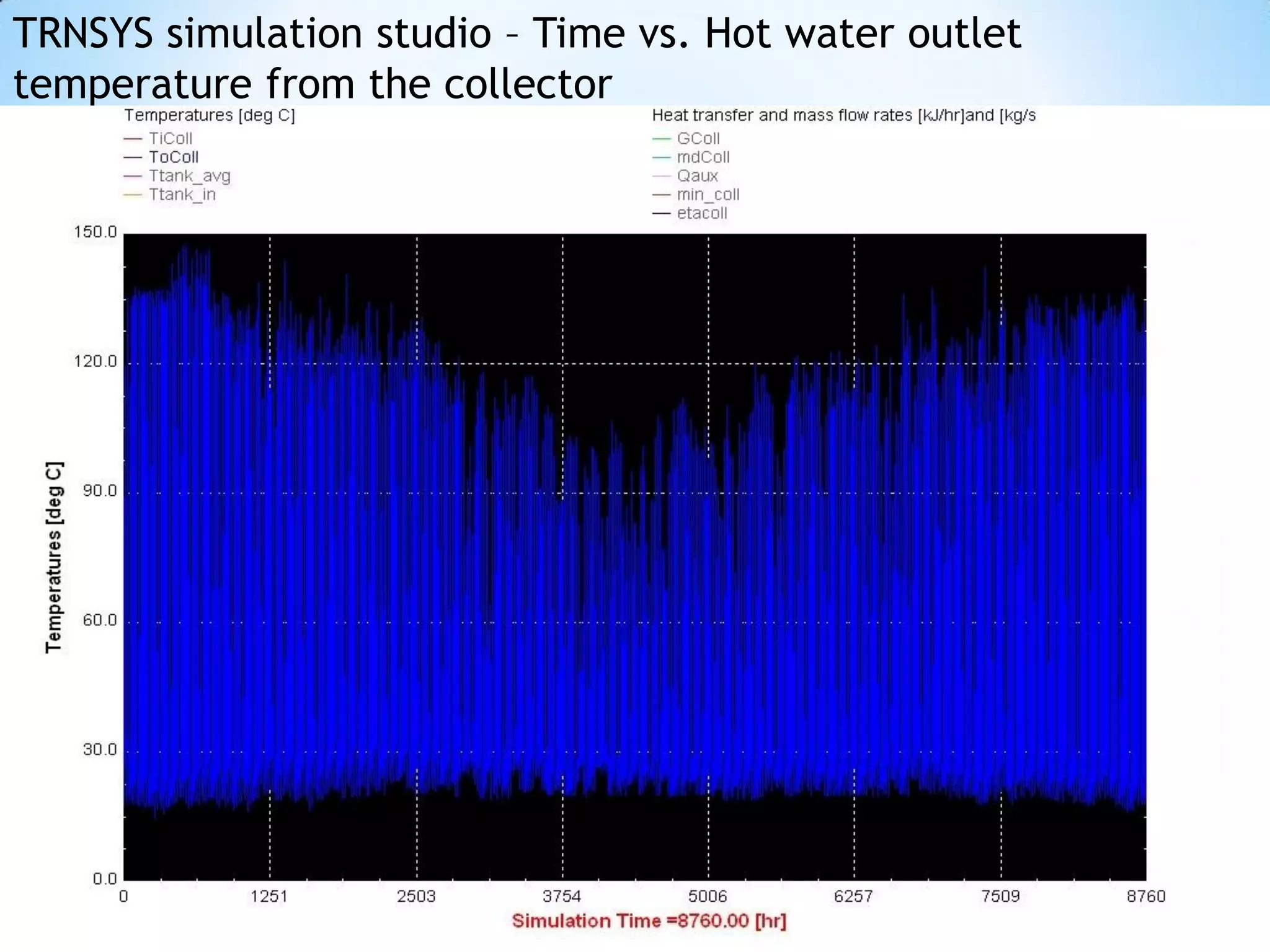
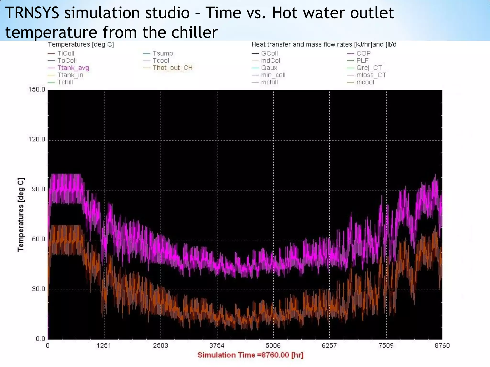
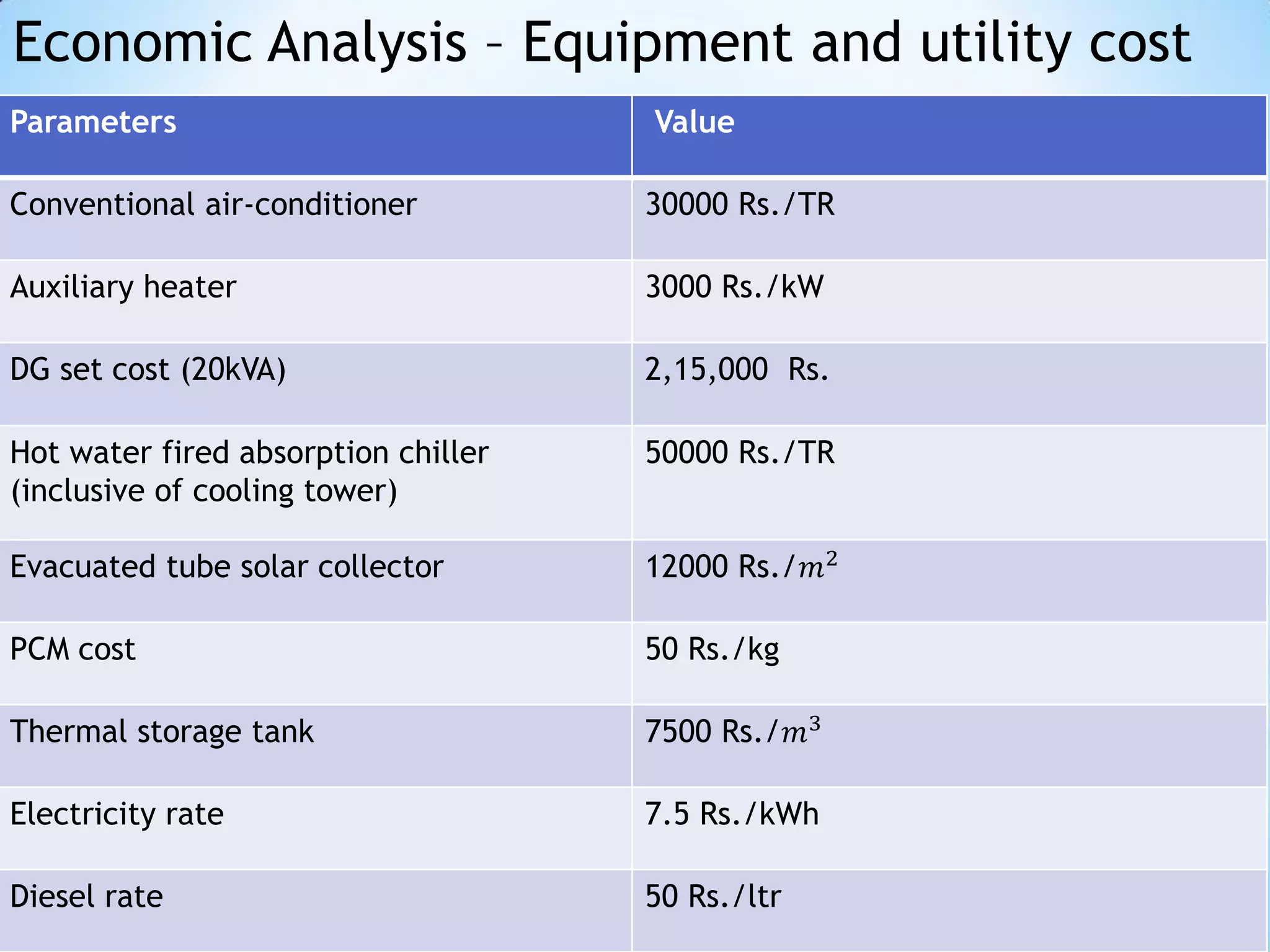
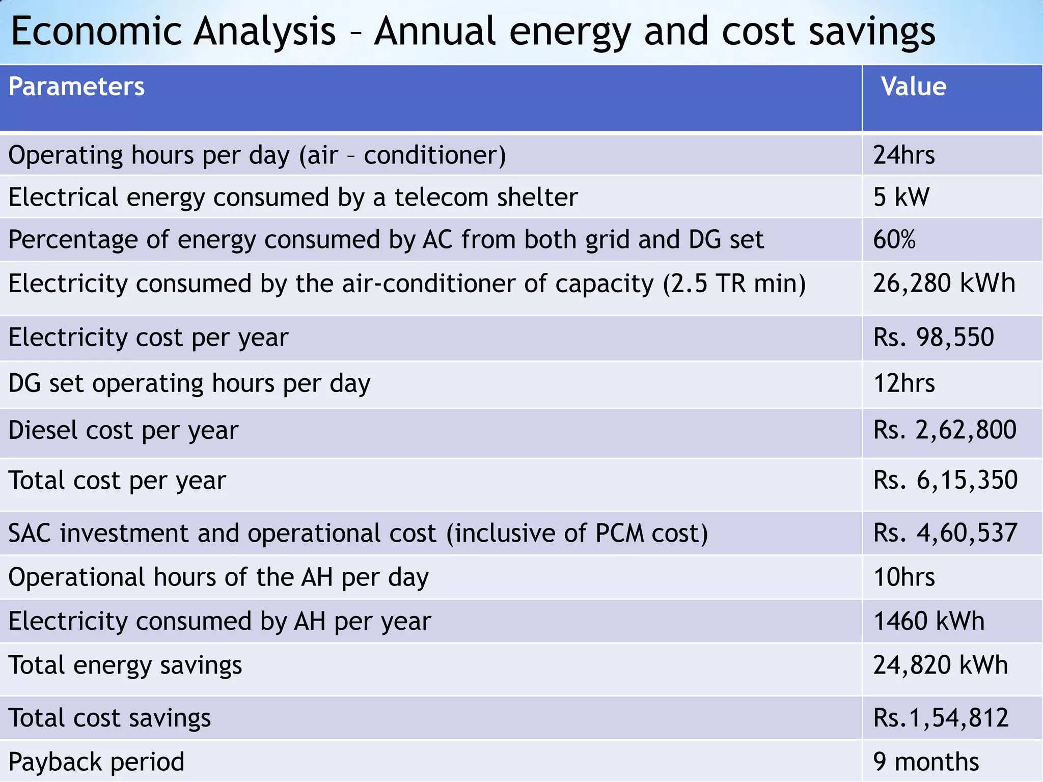
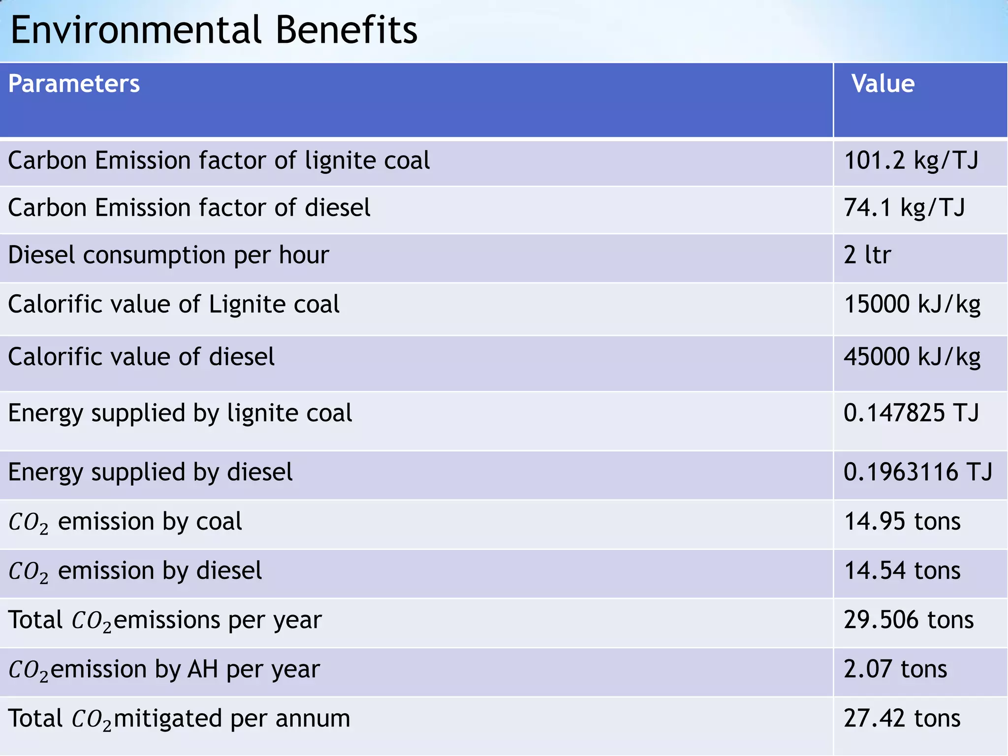

The document summarizes the design and analysis of a solar absorption chiller with phase change material (PCM) for cooling telecommunication shelters in India. It includes the theoretical model of the absorption chiller, building simulation using TRNSYS software, analysis of system components like the solar collector and cooling tower, and economic and environmental analysis. The results show that the solar cooling system can achieve energy savings of 24,820 kWh per year and cost savings of Rs. 1,54,812 with a payback period of 9 months, while mitigating 27.8 tons of CO2 emissions annually compared to a conventional cooling system.


![Coded Agents – with UiPath SDK + LangGraph [Virtual Hands-on Workshop]](https://cdn.slidesharecdn.com/ss_thumbnails/codedagentsdeck-251215155422-5497c599-thumbnail.jpg?width=640&height=640&fit=bounds)


![Vibe Coding vs. Spec-Driven Development [Free Meetup]](https://cdn.slidesharecdn.com/ss_thumbnails/vibecodingvsspecdrivendevelopment-251209105622-43f455e7-thumbnail.jpg?width=640&height=640&fit=bounds)
