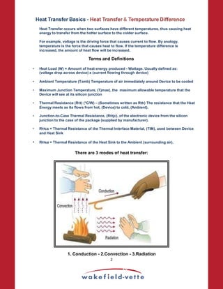
1) Heat transfer occurs between surfaces at different temperatures, with heat flowing from hot to cold. Thermal management should be considered early in design.
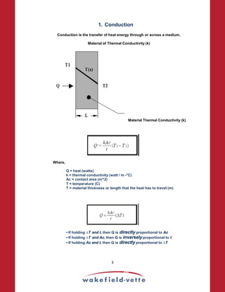
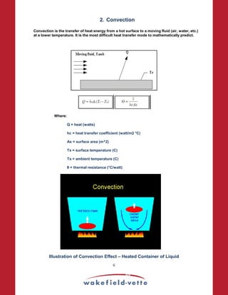
2) There are three modes of heat transfer - conduction, convection, and radiation. Conduction is heat transfer through a medium, convection involves heat transfer via a moving fluid, and radiation transfers heat electromagnetically.
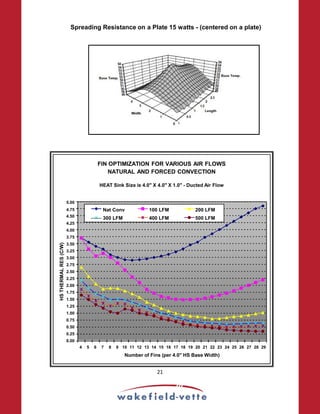
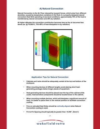
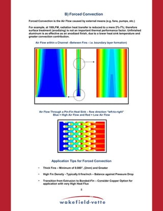
3) Forced convection using fans is more effective than natural convection for cooling electronics, as it can transfer more heat away from components than airflow caused by natural buoyancy alone. Proper fin and system design optimizes forced convection.


![Heat Sink Selection - Example:
• TO-220 package outline device is dissipating 7 watts (Q)
• The Maximum Junction Temperature, is Tj = 125°C
• And the Maximum Ambient Temperature, is Ta = 65°C
• Component Junction-to-Case Thermal Resistance, is Rθjc = 2.5 °C/W
(Note: this information can be obtained from the device’s data sheet).
Assuming that:
• Interface material is Silicon Grease – Wakefield 120 Series
• 0.002 inches thick
• 0.36 in2 contact area
The Thermal Resistance of Silicon Oil-Based Grease can be found to be as:
Thermal Resistivity, (ρ), (120 Series = 56 C-in/W), thickness, (t), (in) and contact
area, (A), (in^2)
θcs = 56 C-in/W x 0.002 in / 0.36 in^2 = 0.311°C/W
Θsa = [(Tj − Ta) / Q] − (Θjc +Θcs)
Θsa = [(Tj − Ta) / Q] − (Θjc +Θcs)
Θsa = [(125C – 65C) / 7W] − (2.5C/W + 0.31C/W)
Θsa = 5.76°C/W
A heat sink will be required with a Thermal Resistance of less than or equal to 5.76°C/W.
Extrusion Data:
17](https://image.slidesharecdn.com/heat-sink-design-for-thermal-analysis-230820194116-2205a686/85/heat-sink-design-for-thermal-analysis-pdf-18-320.jpg)