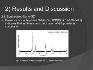
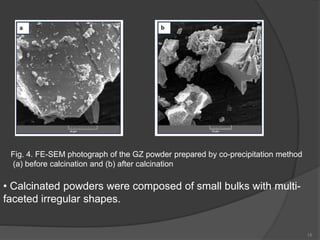
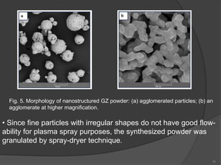
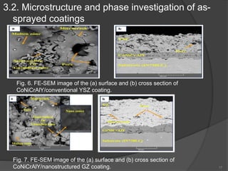
Contents
 Introduction
 Structure of TBC
 Material selection
 TBC deposition methods
 Case Study
 Conclusion
 References
1
Introduction
 Thermal barrier coatings (TBC) are ceramic layers deposited
over metallic parts in order to provide their thermal insulation
from the high temperature conditions.
 Reduce the material losses from the functional surfaces which
are working at high temperature.
 TBC enables engines to operate at temperatures above the
melting temperature of the superalloy.
2
Structure of TBC
 Bond Coat with a thickness of about
75-100 μm providing strong
adhesion of the outer ceramic layer
to the substrate surface
 Thermally-grown oxide (TGO) layer
of about 0.1-10 μm thick has a
structure that has low diffusivity for
oxygen.
 The ceramic topcoat of thickness
100-300 μm is having very low
thermal conductivity.
3
Material Selection
 Low thermal conductivity
 Matched coefficient of thermal expansion
(CTE)
 Thermal stability
4
TBC deposition methods
 As stated earlier the Thermal Barrier Coatings can be
produced in industries by the following methods:
1. Air Plasma Spray (APS)
2. Electron Beam Physical Vapour Deposition (EBPVD)
3. High Velocity Oxygen Fuel (HVOF)
4. Electrostatic Spray Assisted Vapour Deposition (ESAVD)
5. Direct Vapour Deposition (DVD)
5
APS
6
Fig. 1Principle of DC plasma spray process
Torch body Powder feeder
Case Study
7
Enhancement of hot corrosion resistance of
thermal barrier coatings by using nanostructured
Gd2Zr2O7 coating
 YSZ coatings have a functional operational limit of about
1200 °C due to sintering.
 Low quality fuels often possess impurities such
as vanadium and sodium, which give rise to formation of
V2O5 and Na2SO4 salts on the surface of gas turbines
 The recent studies on TBCs are mainly focused on finding
new materials with two approaches: (1) substitution of Zr-
based coatings and (2) finding better stabilizers
 Rare earth zirconates have the general composition of
A2B2O7 with pyrochlore crystal structure
A is a 3-positive charge cation (La, Gd, …)
B stands for tetravalent cation (Zr, Hf, Ce, …)
8
1) Experimental procedures
1.1. Synthesis of GZ nano-powder by co-precipitation method
 Gadolinium oxide was dissolved in HCl to release Gd3+ ion
 Zirconium oxychloride was dissolved in distilled water
 The obtained precipitants were washed by distilled water and then
filtered and dried at 70 °C for 24 h
 The powders were calcinated at 1000 °C for 2 h
1.2. Nano-GZ granulation
 Nanopowders should able to be sprayed by APS method
 About 20 wt% of synthesized GZ nanopowder was added to distilled
water along with 0.7 wt% Polyvinyl alcohol (PVA) and stirred for 2 h
 To prevent precipitation of GZ nanopowders, they were immediately
granulated by spray-dryer
9
Continued...
1.3. Procedure for applying of TBC
Nickel-based superalloy (IN-738LC) as substrate
Table 1. Chemical compositions of the substrate used in this study and IN 738LC
Prior to the coating, the surface oxide of samples was removed with
sandblasting by alumina particles with grain size of 50–80 mesh under
pressure of 40–50 psi. The samples then rinsed, ultrasonically cleaned in
acetone and finally dried.
10
11
Fig. 1. Results of XRD analysis for YSZ precursor powder
 Two bond/top coat systems of CoNiCrAlY/conventional YSZ and
CoNiCrAlY/nanostructured GZ coatings were applied
 150-micron thick bond coat and 300-micron top coat
Table 2. Parameters of plasma spraying
12
4. Hot corrosion test
 a mixture of 55 wt% V2O5 and 45 wt% Na2SO4 was prepared. About 30
mg/cm of the mixture was placed on the sample surfaces
 Samples were heated from room temperature to 950 °C.
 After each 4 h, the sample surface was investigated
 Field emission scanning electron microscope (FESEM/EDS,
MIRA3TESCAN-XMU and Xray diffraction ((XRD, Philips X'pert) Cu Kα,
40 kV, 30 mA, Step size: 0.02°) were also employed for determination of
structural and phase constituents of the coatings before and after hot
corrosion test.
13
2) Results and Discussion
2.1. Synthesized Nano-GZ
 Presence of single phase Gd2Zr2O7 (JCPDS: # 01-080-0471)
indicates that synthesis and calcination of GZ powder is
successful
Fig. 3. Results of XRD analysis for GZ after calcination
14
15
Fig. 4. FE-SEM photograph of the GZ powder prepared by co-precipitation method
(a) before calcination and (b) after calcination
• Calcinated powders were composed of small bulks with multi-
faceted irregular shapes.
16
Fig. 5. Morphology of nanostructured GZ powder: (a) agglomerated particles; (b) an
agglomerate at higher magnification.
• Since fine particles with irregular shapes do not have good flow-
ability for plasma spray purposes, the synthesized powder was
granulated by spray-dryer technique.
3.2. Microstructure and phase investigation of as-
sprayed coatings
17
Fig. 6. FE-SEM image of the (a) surface and (b) cross section of
CoNiCrAlY/conventional YSZ coating.
Fig. 7. FE-SEM image of the (a) surface and (b) cross section of
CoNiCrAlY/nanostructured GZ coating.
 Porosities of the different layers, as measured by image processing, were
found to be approximately 3–5% for the CoNiCrAlY layer, 12–15% on the
YSZ layer and 7–10% on the GZ layers
 In conventional YSZ coating pores and microcracks can be observed in the
cross section of both layers and also in outer surface of the coating. While
in nanostructured GZ made from ultrafine particles in the pores
inhomogeneities are reduced considerably
18
Fig. 8. FE-SEM micrograph of the fracture surface of
(a) CoNiCrAlY/conventional YSZ (b) CoNiCrAlY/nanostructured GZ coatings
19
Fig. 9. XRD patterns from the surface of (a)
conventional YSZ and (b) nanostructured GZ coatings
X-ray diffraction analysis was
carefully studied to ensure the
formation of the tetragonal
structure and the absence of
the cubic structure in the YSZ
coating. Cubic structure of
zirconia could be distinguished
from the tetragonal structure by
the presence
2.3. Microstructure of the coatings after hot
corrosion test
20
Fig. 10. FE-SEM image of CoNiCrAlY/conventional YSZ coating after 20 h
corrosion test.: (a) the surface; (b) the cross section.
Fig. 11. FE-SEM image of CoNiCrAlY/nanostructured GZ coating after 28 h
corrosion test.: (a) the surface; (b) the cross section
 Conventional YSZ and nanostructured GZ layers have cracks and
spallation near the CoNiCrAlY layer. The thermal expansion
mismatch is one of the key factors
CTE is 8–9 × 10−6 K−1 for GZ
10.5–11.5 × 10−6 K−1 for 8YSZ
15.0 × 10−6 K−1 at 1000 °C for CoNiCrAlY
 Another reason for the crack propagation of GZ and YSZ coatings is
its low fracture toughness (~1 MPa·m for GZ coating, and ~2
MPa·m for 8YSZ coating)
21
3 . Conclusion
 CoNiCrAlY/nanostructured Gd2Zr2O7 is more resistant to hot
corrosion than CoNiCrAlY/conventional YSZ.
 The improved hot corrosion resistance could be explained by
the change of structure to a dense and more packed
structure in the nano-coating.
 Sodium sulfate and vanadium oxide dissolve the stabilizer of
the zirconia at high temperatures; hence, resulting
crack, spallation of surface layers of conventional YSZ and
nanostructured Gd2Zr2O7 TBCs.
 Gd2O3 has a higher acidity than Y2O3 which means that the
driving force of reaction Y2O3 + NaVO3 is larger than that of
reaction Gd2O3 + NaVO3. Therefore, Gd2Zr2O7 is more
resistant to hot corrosion than YSZ.
22
References
 M. Bahamirian , S.M.M. Hadavi , M. Farvizi , M.R. Rahimipour , A.
Keyvani
Enhancement of hot corrosion resistance of thermal barrier coatings by
using nanostructured Gd2Zr2O7 coating
Surface and Coatings Technology volume360, 25 February 2019,
Pages 1-12
 Wikipedia https://en.wikipedia.org/wiki/Thermal_barrier_coating
 NPTEL https://nptel.ac.in/courses/112107248/23
23
Thank You !!
24

Thermal barrier coatings (tbc)

  • 1.
    Contents  Introduction  Structureof TBC  Material selection  TBC deposition methods  Case Study  Conclusion  References 1
  • 2.
    Introduction  Thermal barriercoatings (TBC) are ceramic layers deposited over metallic parts in order to provide their thermal insulation from the high temperature conditions.  Reduce the material losses from the functional surfaces which are working at high temperature.  TBC enables engines to operate at temperatures above the melting temperature of the superalloy. 2
  • 3.
    Structure of TBC Bond Coat with a thickness of about 75-100 μm providing strong adhesion of the outer ceramic layer to the substrate surface  Thermally-grown oxide (TGO) layer of about 0.1-10 μm thick has a structure that has low diffusivity for oxygen.  The ceramic topcoat of thickness 100-300 μm is having very low thermal conductivity. 3
  • 4.
    Material Selection  Lowthermal conductivity  Matched coefficient of thermal expansion (CTE)  Thermal stability 4
  • 5.
    TBC deposition methods As stated earlier the Thermal Barrier Coatings can be produced in industries by the following methods: 1. Air Plasma Spray (APS) 2. Electron Beam Physical Vapour Deposition (EBPVD) 3. High Velocity Oxygen Fuel (HVOF) 4. Electrostatic Spray Assisted Vapour Deposition (ESAVD) 5. Direct Vapour Deposition (DVD) 5
  • 6.
    APS 6 Fig. 1Principle ofDC plasma spray process Torch body Powder feeder
  • 7.
  • 8.
    Enhancement of hotcorrosion resistance of thermal barrier coatings by using nanostructured Gd2Zr2O7 coating  YSZ coatings have a functional operational limit of about 1200 °C due to sintering.  Low quality fuels often possess impurities such as vanadium and sodium, which give rise to formation of V2O5 and Na2SO4 salts on the surface of gas turbines  The recent studies on TBCs are mainly focused on finding new materials with two approaches: (1) substitution of Zr- based coatings and (2) finding better stabilizers  Rare earth zirconates have the general composition of A2B2O7 with pyrochlore crystal structure A is a 3-positive charge cation (La, Gd, …) B stands for tetravalent cation (Zr, Hf, Ce, …) 8
  • 9.
    1) Experimental procedures 1.1.Synthesis of GZ nano-powder by co-precipitation method  Gadolinium oxide was dissolved in HCl to release Gd3+ ion  Zirconium oxychloride was dissolved in distilled water  The obtained precipitants were washed by distilled water and then filtered and dried at 70 °C for 24 h  The powders were calcinated at 1000 °C for 2 h 1.2. Nano-GZ granulation  Nanopowders should able to be sprayed by APS method  About 20 wt% of synthesized GZ nanopowder was added to distilled water along with 0.7 wt% Polyvinyl alcohol (PVA) and stirred for 2 h  To prevent precipitation of GZ nanopowders, they were immediately granulated by spray-dryer 9
  • 10.
    Continued... 1.3. Procedure forapplying of TBC Nickel-based superalloy (IN-738LC) as substrate Table 1. Chemical compositions of the substrate used in this study and IN 738LC Prior to the coating, the surface oxide of samples was removed with sandblasting by alumina particles with grain size of 50–80 mesh under pressure of 40–50 psi. The samples then rinsed, ultrasonically cleaned in acetone and finally dried. 10
  • 11.
    11 Fig. 1. Resultsof XRD analysis for YSZ precursor powder
  • 12.
     Two bond/topcoat systems of CoNiCrAlY/conventional YSZ and CoNiCrAlY/nanostructured GZ coatings were applied  150-micron thick bond coat and 300-micron top coat Table 2. Parameters of plasma spraying 12
  • 13.
    4. Hot corrosiontest  a mixture of 55 wt% V2O5 and 45 wt% Na2SO4 was prepared. About 30 mg/cm of the mixture was placed on the sample surfaces  Samples were heated from room temperature to 950 °C.  After each 4 h, the sample surface was investigated  Field emission scanning electron microscope (FESEM/EDS, MIRA3TESCAN-XMU and Xray diffraction ((XRD, Philips X'pert) Cu Kα, 40 kV, 30 mA, Step size: 0.02°) were also employed for determination of structural and phase constituents of the coatings before and after hot corrosion test. 13
  • 14.
    2) Results andDiscussion 2.1. Synthesized Nano-GZ  Presence of single phase Gd2Zr2O7 (JCPDS: # 01-080-0471) indicates that synthesis and calcination of GZ powder is successful Fig. 3. Results of XRD analysis for GZ after calcination 14
  • 15.
    15 Fig. 4. FE-SEMphotograph of the GZ powder prepared by co-precipitation method (a) before calcination and (b) after calcination • Calcinated powders were composed of small bulks with multi- faceted irregular shapes.
  • 16.
    16 Fig. 5. Morphologyof nanostructured GZ powder: (a) agglomerated particles; (b) an agglomerate at higher magnification. • Since fine particles with irregular shapes do not have good flow- ability for plasma spray purposes, the synthesized powder was granulated by spray-dryer technique.
  • 17.
    3.2. Microstructure andphase investigation of as- sprayed coatings 17 Fig. 6. FE-SEM image of the (a) surface and (b) cross section of CoNiCrAlY/conventional YSZ coating. Fig. 7. FE-SEM image of the (a) surface and (b) cross section of CoNiCrAlY/nanostructured GZ coating.
  • 18.
     Porosities ofthe different layers, as measured by image processing, were found to be approximately 3–5% for the CoNiCrAlY layer, 12–15% on the YSZ layer and 7–10% on the GZ layers  In conventional YSZ coating pores and microcracks can be observed in the cross section of both layers and also in outer surface of the coating. While in nanostructured GZ made from ultrafine particles in the pores inhomogeneities are reduced considerably 18 Fig. 8. FE-SEM micrograph of the fracture surface of (a) CoNiCrAlY/conventional YSZ (b) CoNiCrAlY/nanostructured GZ coatings
  • 19.
    19 Fig. 9. XRDpatterns from the surface of (a) conventional YSZ and (b) nanostructured GZ coatings X-ray diffraction analysis was carefully studied to ensure the formation of the tetragonal structure and the absence of the cubic structure in the YSZ coating. Cubic structure of zirconia could be distinguished from the tetragonal structure by the presence
  • 20.
    2.3. Microstructure ofthe coatings after hot corrosion test 20 Fig. 10. FE-SEM image of CoNiCrAlY/conventional YSZ coating after 20 h corrosion test.: (a) the surface; (b) the cross section. Fig. 11. FE-SEM image of CoNiCrAlY/nanostructured GZ coating after 28 h corrosion test.: (a) the surface; (b) the cross section
  • 21.
     Conventional YSZand nanostructured GZ layers have cracks and spallation near the CoNiCrAlY layer. The thermal expansion mismatch is one of the key factors CTE is 8–9 × 10−6 K−1 for GZ 10.5–11.5 × 10−6 K−1 for 8YSZ 15.0 × 10−6 K−1 at 1000 °C for CoNiCrAlY  Another reason for the crack propagation of GZ and YSZ coatings is its low fracture toughness (~1 MPa·m for GZ coating, and ~2 MPa·m for 8YSZ coating) 21
  • 22.
    3 . Conclusion CoNiCrAlY/nanostructured Gd2Zr2O7 is more resistant to hot corrosion than CoNiCrAlY/conventional YSZ.  The improved hot corrosion resistance could be explained by the change of structure to a dense and more packed structure in the nano-coating.  Sodium sulfate and vanadium oxide dissolve the stabilizer of the zirconia at high temperatures; hence, resulting crack, spallation of surface layers of conventional YSZ and nanostructured Gd2Zr2O7 TBCs.  Gd2O3 has a higher acidity than Y2O3 which means that the driving force of reaction Y2O3 + NaVO3 is larger than that of reaction Gd2O3 + NaVO3. Therefore, Gd2Zr2O7 is more resistant to hot corrosion than YSZ. 22
  • 23.
    References  M. Bahamirian, S.M.M. Hadavi , M. Farvizi , M.R. Rahimipour , A. Keyvani Enhancement of hot corrosion resistance of thermal barrier coatings by using nanostructured Gd2Zr2O7 coating Surface and Coatings Technology volume360, 25 February 2019, Pages 1-12  Wikipedia https://en.wikipedia.org/wiki/Thermal_barrier_coating  NPTEL https://nptel.ac.in/courses/112107248/23 23
  • 24.