
Recommended
Recommended
More Related Content
What's hot
What's hot (20)
Similar to The Rang Bot - CNC Rangoli Maker
Similar to The Rang Bot - CNC Rangoli Maker (20)
Recently uploaded
Recently uploaded (20)
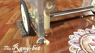
The Rang Bot - CNC Rangoli Maker
- 1. The Rang-bot
- 2. The Rang-bot Precision Rangoli Maker
- 3. OUTLINE 1. A small Description of Rangoli Maker 2. Components of the robot 3. The Robot - Main Body 4. The softwares and Microcontroller 5. The Colour dispenser
- 4. Some concepts we need to learn : A. CNCs What we are essentially trying to construct here is a CNC or computer numerical control machine. CNC machining is a manufacturing process in which pre-programmed computer software dictates the movement of factory tools and machinery. Using this, we can accomplish several complex 3D/2D cutting and printing tasks with a single set of prompts. The language behind CNC machining is alternately referred to as G-code, and it’s written to control the various behaviors of a corresponding machine, such as the speed, feed rate and coordination. In today’s CNC protocols, the production of parts via pre-programmed software is mostly automated. The dimensions for a given part are usually set into place with computer-aided design (CAD) software and then converted into an actual finished product with computer-aided manufacturing (CAM) software. However, for our purposes, we will not need these CAD or CAM as we are merely creating a simple 2D model, which we can easily convert to G Code and input into our arduino. Speaker : Narendra Kumar
- 5. B. G Code G-code, or “geometric code”, is a programming language for CNC that instructs machines where and how to move. Most machines speak a different “dialect” of g-code, so the codes vary depending on type, make, and model. G-code follows some variation of the alpha numeric pattern: N## G## X## Y## Z## F## S## T## M##, where N is the Line number or which line of the 2D model we are at (for indexing) , G is the Motion, i.e. how fast the nozzle moves or in what pattern (Circular, straight, etc.), X, Y and Z are the destination coordinates, F is the Feed rate, for defining the surface speed of the cutting tool in inches per min, S is the Spindle speed, which is the rotational speed of the cutting tool in revolutions per min, T is the Tool selection, to select which mill or lathe to use, and M refers to the Miscellaneous functions like coolant, spindling, etc. We will not need all of these functions for our purposes (Just flow rate, motion type and X and Y coordinates), however most G-Code implementing machines require all these parameters. We will be using the in built Arduino G-Code library, linked here- https://create.arduino.cc/projecthub/tinkersprojects/g-code-arduino-library- 1a2bd6#:~:text=G%2Dcode%20is%20a%20set,saved%20on%20an%20SD%20card.
- 6. About Rangoli Maker The Rang-Bot The Rang-Bot is a robot which can draw a uniColoured rangoli over a particular area. It takes an image of rangoli as input and reproduces the same on a plane floor. For that we have created a novel design which is cost efficient, precise and robust.
- 7. Bot Specifications 1. dx = 0.0055 mm, dy =1.177 mm ( dx is distance traveled by nozzle in x direction with stepper motor moving a minimum angle.) 2. Drawing space of 60 cm * y where y is at least 5 mm. 3. Orifice diameter of powder dispenser is 5mm. 4. Power consumption : 22 W (may vary). 5. Battery backup for continuous use : 1 - 2 Hrs (May vary) 6. Robot Dimensions : 47 cm * 108 cm * 57 cm
- 8. Components 1. The Robot - Main Body 2. Microcontroller and Softwares used 3. Colour Dispenser Our Whole system consists of 3 major Parts. In next slides, we will talk about the following of each of the above mentioned parts. A. Purpose B. Component used C. Model D. Working Speaker : Yogesh Yadav
- 9. Block Diagram Scan2CAD Vector Image Scan2CAD G code file To steppers and servos
- 10. 1. The Robot - Main Body A. Purpose For drawing a rangoli, this is the main frame of hardware used to move the colour dispenser in a 2d Plane. It consists of two stepper motors which will move the dispenser in x axis and y axis independently. It allows the colour dispenser to move within a width of 60cm.
- 11. B. Components Used S.No. Description Specifications Quantity 1 Stepper Motor Nema17 4.2 Kg cm 2 2 Wheels Diameter 15cm 2 3 Steel Rods L=750mm, 10mm ⌀ 3 4 Threaded Rod L=750mm, 10mm ⌀, Pitch = 1.5mm 1 5 Ball bearings 10mm,10mm ⌀ (inner) 6 6 Caster Wheels 4cm 4 7 Gears 25 mm, 50 mm 2 each 8 Cylindrical Ball bearings 10mm ⌀ (inner) 2 9 Hex Nut 10mm ⌀ (inner), Pitch = 1.5mm 1
- 12. C. Model a. Isometric view b. Top view
- 15. D. Working The model has similar working as any other CNC machine. The nut attached on the dispenser is constrained to move along the rod and the rods are constrained to move with the bot guided by the wheels. Hence, we have two steppers to move the dispenser in a 2D plane. We can see that there is no bound to y- axis. Our model can cover up a area of 60 cm *y where y can be any length greater than dy i.e. 0.117mm. The steel rails are used to guide and support the dispenser to move along x-axis. We have used a gear system of torque gain of 2 which will increase the precision and power of the bot along both axis. We have also used caster wheels to support our bot from toppling.
- 16. 2. Software part and microcontroller A. Purpose The main goal we wish to accomplish with the software portion of our model is to convert our picture from its JPEG format to a G-Code format. From here, we can input this G-Code into our microcontroller to use the motors to create a final rangoli. Speaker : Parth Bajaj
- 17. B. Components Used S.No. Description Specifications Quantity 1 Microcontroller Arduino UNO 1 2 Lipo rechargeable battery 11.1 V 2200 mAH 1 3 Stepper Motor drivers A3967 Microstepping Driver 1 4 Stepper motor Nema 14 2 5 Jumper Wires - -
- 18. Components
- 19. C. Circuit for single axis
- 20. D. Working Software- The G-code we will use for our purposes has just 4 parameters- G## X## Y## F## where, G is the Motion, i.e. how fast the nozzle moves or in what pattern (Circular, straight, etc.), X and Y are the destination coordinates and F is the Feed rate, for defining the surface speed of the dispensing tool in inches per min. The main functions we will use are G00 X## Y## F## or G90 to set- Absolute mode, where the dispenser dispenses in a line with flow rate F to the destination (X,Y), G01 X## Y## F## or G91 to set- Relative mode, where the dispenser moves (X,Y) amount from the current position at speed F, G04 P##, where the CNC will do nothing for P seconds, G92 X## Y##, where the dispenser will move to (X,Y) and G02 X##Y##I##J## for clockwise and similar G03 for counterclockwise arcs, where I and J are the relative coordinates from the start point to the center and X and Y are the endpoints.
- 21. D. Working To actually convert our image to G-Code, we would first have to convert the raster image into a vector one. This can be done manually by sketching along the boundaries of the image, however certain online converters definitely save a lot more time. After this, our G-Code would be generated by starting at any vector (Usually (0,0) or center) and tracing each vector using the relative move mode. If we reach a point that has already been completed, we can search for any unfinished vectors in the image and move our cursor there and start again. The basic idea here is to trace all the vectors in the image. Realistically, we were planning on using a software like Scan2CAD to directly vectorize and generate G-Code for our JPEG image.
- 22. D. Working Microcontroller- Once we obtain our G-Code, we need a program that allows us to input that to our arduino. This program will be in C++ and have 5 main functions- 1. Setup- To setup the controller, put initial position to (0,0), set a default flow rate and open coms. 2. Loop- To be run continuously once setup is complete, whose purpose is to read a command, store it and call the function that processes your command. 3. Process command- It searches for the G value and calls either line or arc depending on the command. It can also call the position function to position the dispenser or to wait for a given amount of time, or even tell the current position of the nozzle. 4. Line- This is a simple function that can be used to create a line, depending on which mode is active. For this, we use m1step and m2step functions which are inbuilt in arduino library to move the motors to create the required line. 5. Arc- This is a similar function as line, used for creating arcs. It finds the angle and radius of the arc and breaks it up into small lines, which it then creates.
- 23. D. Working Auxiliary functions- 1. ParseNumber- For finding number after code (G23 would return 23 if searching for G value) 2. Help- Displays options 3. Where- returns the current position of nozzle 4. Ready- Creates ready state at the start of every loop 5. Output- Prints a string (For debugging) 6. Atan3- is the inverse tan of a given dy/dx ( Accounts of negative angles also) 7. Position- Repositions nozzle 8. Feedrate- Sets a Feed Rate 9. Pause- Takes a break, eats a kitkat. Source code- https://github.com/MarginallyClever/GcodeCNCDemo/blob/master/GcodeCNCDemo2Axis/GcodeCNC Demo2Axis.ino
- 24. 3. Colour Dispenser A. Purpose This is the nozzle system we use to dispense the colour stored. We analysed that color drop is not simple achieved just through a simple opening. So we created a mechanism to control the flow of colour in a better way. It will help us to regulate the flow of colour smoothly without any glitches. Speaker : Mrinal Mahato
- 25. B. Components Used S.No. Description Specifications Quantity 1 Geared DC motor 10 RPM, 12 V 1 2 MOSFET N-Channel MOSFET 60V 30A 1 3 Resistor 10k ᘯ 1 4 Diode Rectifier 1A 50V 1 5 Push Button for manual cleaning Generic 1 6 Rangoli Colour Generic 200gm 7 Twisted plate 50mm 1 8 Ball Bearing 10mm,10mm ⌀ (inner) 1 9 3D printed bottle Autocad model attached 1 10 3D printed solid Frame structure Autocad model attached 1
- 27. C. Model 3D Dispenser Model 3D modified bottles for different colours Geared DC motor Dispensing Mechanism
- 29. D. Working The Colour is fed into the main chamber of the dispenser from a container with powder above it. This main chamber is fitted with a screw inside, the head of which is attached to a geared DC motor located right outside the main chamber. When this turns, the rearmost groove of the screw fills with Colour and the frontmost on pushes that Colour out of the nozzle. If the motor is turned faster, it increases the flow rate. With this design, we are able to lower the size of orifice which will help us to increase the precision.
- 30. Final Model and Circuit
- 32. Extensions We can extend this by allowing it to create multi-Coloured images. How this can be done is by using image processing techniques to isolate the two Colours and vectorize both those images separately. This will create two layers, and when we generate the G-Code for both of these, putting a pause function in between, that will allow us to detach and clean the dispenser and replace the Colour on top, without disturbing the Rangoli. After this, we reset the nozzle to (0,0) and print a second layer. This will allow us to create multi-Coloured rangoli, as we can extend this to n Colours. Speaker : Parth Bajaj
- 34. Thank YOU!