Downloaded 42 times

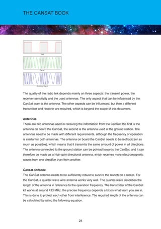
![23
THE CANSAT BOOK
The NETWORKID can be set from 0 to 255 and that changes the physical channel used
for the link (i.e. the frequency). Although in this guide the NETWORKID is considered a
parameter, it can be changed during runtime. For this, you will need to re-initialise the library.
The NODEID is the node in a particular channel and can be set from 1 to 255. Therefore, we
can have up to 255 qbcan operating in the same frequency, although they cannot transmit at
the same time. Messages are generally send to a specific node and that is the GATEWAYID.
So if you are configuring a transmitter/receiver make sure that you are transmitting to the
correct node. Also a receiver can sniff all the packets in a network, thus receiving all traffic
in that network independently if the messages where addressed to that particular node. To
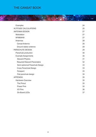
configure the radio on the setup you can just use the following code.
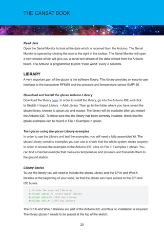
To send data through the network use the following code.
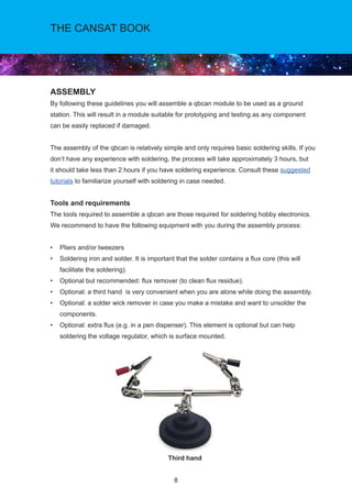
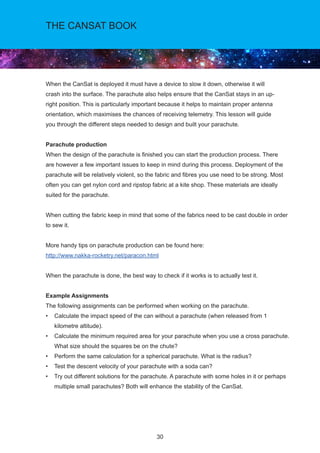
In the radio.send() function, the last argument is the length of the message to be
transmitted In the example above the message payload is 50 bytes long and we are sending
it in full although the actual message is not that long (so it could be optimised).
void setup() {
//Initialize serial connection for debugging
Serial.begin(9600);
//Initialize radio
radio.initialize(FREQUENCY,NODEID,NETWORKID);
radio.setHighPower(); //Use the high power capabilities of the RFM69HW
radio.encrypt(ENCRYPTKEY);
Serial.println(“Transmitting at 433 Mhz”);
}
//Send Data
char payload[50];
sprintf(payload,”T: %d C, P: %d mb.”,(int)T,(int)P); Serial.print(payload);
radio.send(GATEWAYID, payload, 50);
Serial.println(“Send complete”);](https://image.slidesharecdn.com/thecansatbook2016-2017versienov2016-170311155657/85/The-can-sat_book_2016-2017_versienov2016-23-320.jpg)
![24
THE CANSAT BOOK
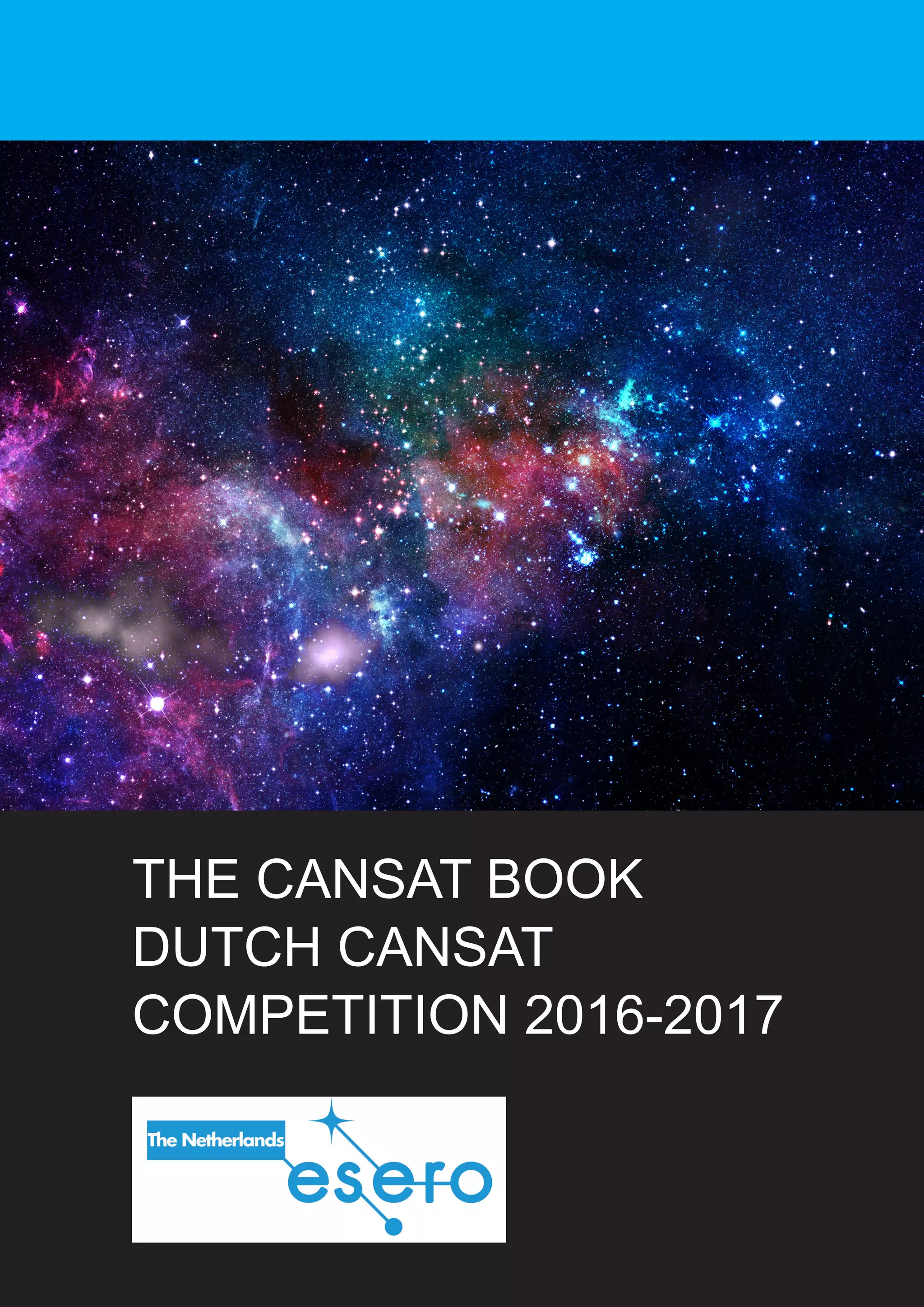
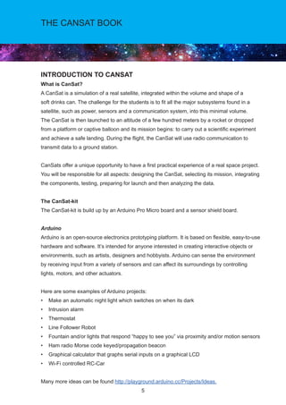
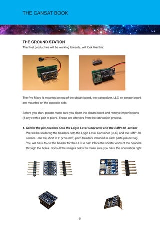
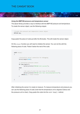
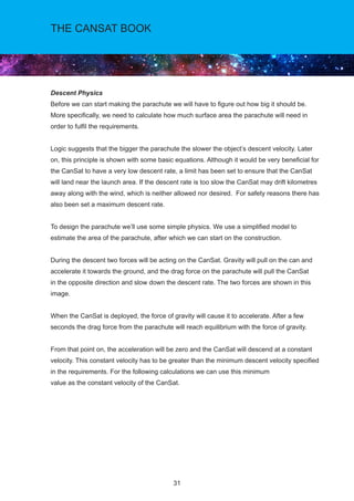
In order to receive data transmitted through the network, the following piece of code can be
used:
Use radio.promiscuous(true); to activate the “promiscuous” mode to listen to all packets from
the network in use.
There are also some other functions that you may find useful when receiving messages:
radio.SENDERID - returns the sender node id.
radio.TARGETID - returns the message target node id (in case you are sniffing all the packets
in the network).
radio.RSSI - returns the received signal strength (RSSI).
EXAMPLES
The provided library contains examples that can help you get started. The examples can
be found in the Arduino IDE by clicking on File Examples qbcan. There is one example,
labelled as CanSat that transmits data and another one labelled as GroundStation that will
receive it.
The GroundStation example can be used with another qbcan to receive this data. To do so,
open the serial monitor in Tools Serial Monitor and set the speed of the serial connection to
9600 baud (this value depends on how you define the serial connection in the qbcan code.
See the “Using the RFM69 transceiver” section).
If you run each of the codes on two different qbcan you will be able to send and receive data
and test the sensors. We encourage you to use these examples as a starting point for your
projects.
if (radio.receiveDone())
{
for (byte i = 0; i radio.DATALEN; i++)
Serial.print((char)radio.DATA[i]);
}](https://image.slidesharecdn.com/thecansatbook2016-2017versienov2016-170311155657/85/The-can-sat_book_2016-2017_versienov2016-24-320.jpg)
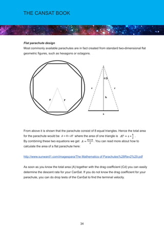
![36
THE CANSAT BOOK
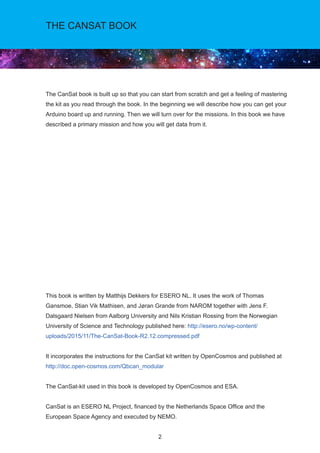
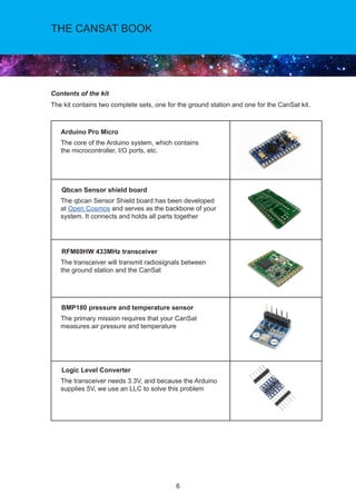
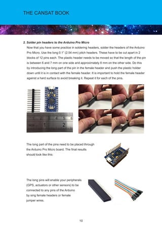
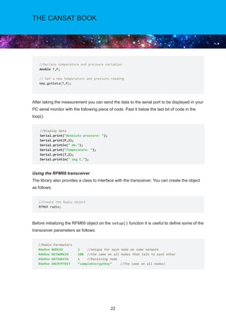
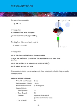
3.3V or 5V respectively. This voltage is regulated by the voltage applied to the RAW
pin. If the board is powered through the ‘RAW’ pin (or USB), this pin can be used as
an output to supply other devices.
RST can be used to restart the Pro Micro. This pin is pulled high by a 10kOhm;
resistor on the board, and is active-low, so it must be connected to ground to initiate
a reset. The Pro Micro will remain “off” until the reset line is pulled back to high.
GND, of course, is the common, ground voltage (0V reference) for the system.
I/O Pins
The Pro Micro’s I/O pins – 18 in all – are multi-talented. Every pin can be used as a digital
input or output, for blinking LEDs or reading button presses. These pins are referenced in
the Arduino IDE via an integer value between 0 and 21. (The A0-A3 pins can be referenced
digitally using either their analog or digital pin number).
Nine pins feature analog to digital converters (ADCs) and can be used as analog
inputs. These are useful for reading potentiometers or other analog devices using the
analogRead([pin]) function.
There are five pins with pulse width modulation (PWM) functionality, which allows
for a form of analog output using the analogWrite([pin], [value]) function. These pins
are indicated on-board with a faint, white circle around them.
There are hardware UART (serial), I2C, and SPI pins available as well. These can be
used to interface with digital devices like serial LCDs, XBees, IMUs, and other serial
sensors.
The Pro Micro has five external interrupts, which allow you to instantly trigger a
function when a pin goes either high or low (or both). If you attach an interrupt to an
interrupt-enabled pin, you’ll need to know the specific interrupt that pin triggers: pin 3
maps to interrupt 0, pin 2 is interrupt 1, pin 0 is interrupt 2, pin 1 is interrupt 3, and pin
7 is interrupt 4.](https://image.slidesharecdn.com/thecansatbook2016-2017versienov2016-170311155657/85/The-can-sat_book_2016-2017_versienov2016-36-320.jpg)


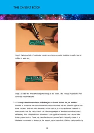
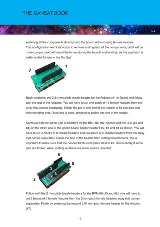
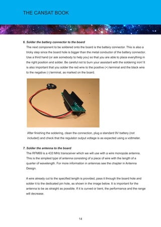
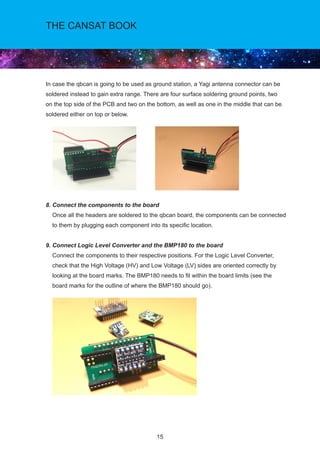
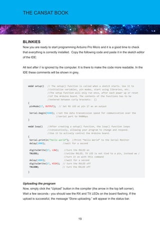
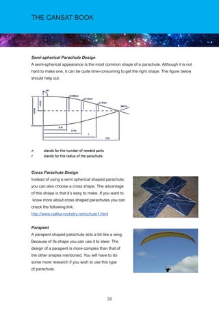
This document provides instructions for assembling a CanSat ground station kit. It describes soldering pin headers to various components like the Arduino, RFM69 radio transceiver, Logic Level Converter, and BMP180 sensor. It also details soldering the voltage regulator, battery connector, and antenna directly to the qbcan circuit board. Finally, it explains how to connect the assembled components to the board and set up the completed ground station kit. The overall assembly process is designed to be straightforward while teaching basic soldering skills needed to construct the CanSat and ground station.