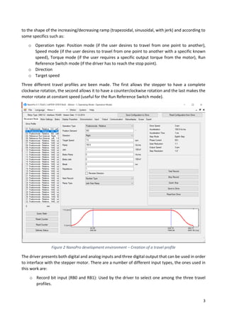
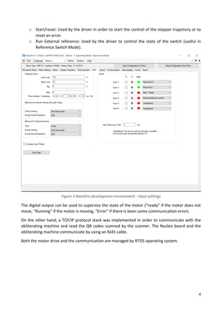
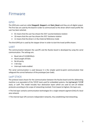
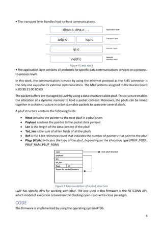
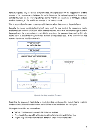
POLITECNICO DI BARI
DIPARTIMENTO DI INGEGNERIA ELETTRICA E
DELL’INFORMAZIONE
CORSO DI LAUREA MAGISTRALE IN
INGEGNERIA DELL’AUTOMAZIONE
Esame di: EMBEDDED CONTROL SYSTEMS
Testing tool for an automated ticketing system
Anno Accademico 2018/2019
Docente:
Prof. Ing. Luca De Cicco
Studente:
Vladimir Zitoli
Contents
Abstract................................................................................................................................................1
Introduction.........................................................................................................................................2
Firmware..............................................................................................................................................5
GPIO..................................................................................................................................................5
UART.................................................................................................................................................5
LwIP STACK.......................................................................................................................................5
CODE.................................................................................................................................................6
Hardware and Results .......................................................................................................................12
Conclusion..........................................................................................................................................13
References .........................................................................................................................................14
1
Abstract
In this report the development of a firmware is presented. The aim of the firmware is to implement
an automated testing tool in order to estimate the reliability of some obliterating machines.
The first part of the report describes how the tool is implemented, while the second one explains
how the firmware is made. Finally, a short illustration of the tool is presented.
2
Introduction
The aim of the project is to develop a firmware which enable a controller to test the reliability of an
obliterating machine that read QR code’s tickets. Particularly, it is required that the tool is able to
scan a number of identical QR codes, which is known the code, at different height from the scanner
and alert the user when the reading is wrong.
As it is not possible to change the height of the scanner, different QR codes are been used, choosing
the one which simulate the correct code. Every time the reading is wrong, an error message is sent
to the user display.
The components used to make the testing tool are:
• Stepper motor (Nanotec PD2-O4118L1804-2)
• Stepper driver (Nanotec SMCI12)
• Power Supply module (DR 75-24)
• Control software for driver (NanoPro v.1.7)
• Microcontroller STM32 NUCLEO F207ZG
• Obliterating machine
Figure 1 Overview of the automated testing tool
The stepper motor is provided with his driver which can do both a position and a velocity control of
the stepper. His holding torque is 0.5 Nm, that is enough for our purposes, and moreover has a high
accuracy (it could reach an accuracy of 0.028° approx.). In order to configure the driver, the control
software NanoPro v.1.7 is used. The software allows the user to create a velocity profile according
3
to the shape of the increasing/decreasing ramp (trapezoidal, sinusoidal, with jerk) and according to
some specifics such as:
o Operation type: Position mode (if the user desires to travel from one point to another),
Speed mode (if the user desires to travel from one point to another with a specific known
speed), Torque mode (if the user requires a specific output torque from the motor), Run
Reference Switch mode (if the driver has to reach the stop point).
o Direction
o Target speed
Three different travel profiles are been made. The first allows the stepper to have a complete
clockwise rotation, the second allows it to have a counterclockwise rotation and the last makes the
motor rotate at constant speed (useful for the Run Reference Switch mode).
The driver presents both digital and analog inputs and three digital output that can be used in order
to interface with the stepper motor. There are a number of different input types, the ones used in
this work are:
o Record bit input (RB0 and RB1): Used by the driver to select one among the three travel
profiles.
Figure 2 NanoPro development environment – Creation of a travel profile
4
o Start/reset: Used by the driver in order to start the control of the stepper trajectory or to
reset an error.
o Run External reference: Used by the driver to control the state of the switch (useful in
Reference Switch Mode).
The digital output can be used to supervise the state of the motor (“ready” if the motor does not
move, “Running” if the motor is moving, “Error” if there is been some communication error).
On the other hand, a TCP/IP protocol stack was implemented in order to communicate with the
obliterating machine and read the QR codes scanned by the scanner. The Nucleo board and the
obliterating machine communicate by using an RJ45 cable.
Both the motor drive and the communication are managed by RTOS operating system.
Figure 3 NanoPro development environment - Input settings
5
Firmware
GPIO
The GPIO pins used are called Stepper0, Stepper1 and Start_Reset and they are all digital output.
The first two are used by the board in order to communicate to the driver which travel profile the
user has been selected.
• 01 means that the user has chosen the 355° counterclockwise rotation
• 10 means that the user has chosen the 355° clockwise rotation
• 11 means that the driver is in Run External Reference mode
The third GPIO pin is used by the stepper driver in order to start the travel profile chosen.
UART
The communication between the user/PC and the Nucleo board is developed by using the serial
communication. The settings are:
• Boud rate of 115200 Bits/s
• Word Length of 8 bits
• No bit parity
• 1 bit stop
• Interrupt mode enabled
The serial communication is used because it is the simpler point-to-point communication that
safeguard the correct behaviour of the prototype (see Code).
LwIP STACK
The protocol stack chosen for the communication between the Nucleo board and the obliterating
machine is an equivalent of the TCP/IP stack used for embedded systems: the Lightweight TCP/IP
stack, or LwIP. This model includes four abstraction layers which are used to sort all related
protocols according to the scope of networking involved. From lowest to highest, the layers are:
• The link layer contains communication technologies for a single network segment (link) of a local
area network.
• The internet layer (IP) connects independent networks, thus establishing internetworking.
6
• The transport layer handles host-to-host communications.
• The application layer contains all protocols for specific data communications services on a process-
to-process level.
In this work, the communication is made by using the ethernet protocol as the RJ45 connector is
the only one available for external communication. The MAC address assigned to the Nucleo board
is 00:80:E1:00:00:00.
The packet buffers are managed by LwIP by using a data structure called pbuf. This structure enables
the allocation of a dynamic memory to hold a packet content. Moreover, the pbufs can be linked
together in a chain structure in order to enable packets to span over several pbufs.
A pbuf structure contains the following fields:
• Next contains the pointer to the next pbuf in a pbuf chain
• Payload contains the pointer to the packet data payload
• Len is the length of the data content of the pbuf
• Tot_len is the sum of all len fields of all the pbufs
• Ref is the 4-bit reference count that indicates the number of pointers that point to the pbuf
• Flags (4 bits) indicates the type of the pbuf, depending on the allocation type (PBUF_POOL,
PBUF_RAM, PBUF_ROM)
LwIP has specific APIs for working with pbuf. The one used in this firmware is the NETCONN API,
which model of execution is based on the blocking open-read-write-close paradigm.
CODE
The firmware is implemented by using the operating system RTOS.
Figure 4 LwIp stack
Figure 5 Rapresentetion of a pbuf structure
7
For our purposes, only one thread is implemented, which provides both the stepper drive and the
manage of the communication between the nucleo board and the obliterating machine. The thread,
called DefaulTask, has the following settings: Normal Priority, use a stack size of 4000 Bytes and use
the function Heap_4.c for an efficient manage of the memory stack.
The structure of the firmware is representable by using a flux diagramm, as shown in figure.
Basically, the thread must initialize the LwIP stack, reach the stop point of the stepper and create
the connection between the nucleo board and the machine. After that, a query message in sent in
loop mode and the response is processed. At the same time, the stepper rotates and the QR code
reader saves in the obliterating machine’s memory the QR codes read. If the connection is not
opened, the thread provides to close it.
Regarding the stepper, it has initially to reach the stop point and, after that, it has to rotate in
clockwise or counterclockwise direction based on the character sent on the serial port.
Three global variables are been defined:
• RxChar: Variable which contains the character received
• PreaviousRxChar: Variable which contains the character received the last time
• FlagRx: Flag variable which indicates if there is a new received character
Figure 6 Flux diagram of the firmware
8
The thread provide to call two functions: InitMotor() and DriveMotor(). The first is called only one
time (outside the loop) to enable the stepper driver to reach the stop point, the second one is called
in the loop every time a character is received from the serial port.
The function HAL_UART_Receive_IT makes the controller listening over the serial, waiting for a new
character. When it is received, the interrupt callback is called and the variable FlagRx switch from 0
(no character received) to 1 (new character received).
Regarding the Nucleo-Machine communication, it is needful to highlight that the packets sent by
the nucleo board (and received from the machine) have a particular structure designed in a special
protocol: the Tool General Purpose – Device Under Test Protocol (TGP – DUT Protocol). As a
consequence, a number of dedicated libraries are been included in the firmware in order to create
(by using the function TGP_DUT_PCKT_SerializeTgpWriteDevice() ) and read (by using the function
TGP_DUT_PCKT_DeserializeTgpReadDeviceAns() ) easily the packets switched from the nucleo to
the machine and viceversa observing the protocol.
The obliterating machine has static IP address 192.168.3.21 while the nucleo board is configured in
order to have the static IP address 192.168.3.19. The chosen port used to communicate is 12345.
The basic configurations (f.i.: IP address of the nucleo, mask, initialization of the stack with RTOS, ..)
are been implemented in MX_LWIP_INIT(). After that, the function InitDataStructures() is used. It
is used only one time (outside the loop) in order to initialize the structures used to communicate
Figure 7 Initialization stepper function
Figure 9 Driving stepper function
Figure 8 UART receive callback function
9
with the obliterating machine (there are been implemented two structures: one of them in order to
switch the QR code reader, the other one in order to send a query message to the machine to have
the last QR code read).
Once the structures are been initialized, the connection is create firstly by using the function
netconn_new(), which create a netconn descriptor, and later by calling the function
netconn_connect(), which fill the structure created by the previous function. If there is not enough
memory to allocate the netconn descriptor the connection won’t be created, else if a connection
error is returned by the second function, the connection will be closed by calling the function
netconn_close().
Once the connection is successfully created, a request of switch on of the QR code reader is sent
from the nucleo to the machine by using the function netconn_write(). After that, a pbuf structure
is created (netbuf_new() ) in order to use it in reception mode. Then, a query message is sent and
the nucleo board turn itself in reception mode (netconn_recv() ). Once the data has been
Figure 10 Initialization data structures code for nucleo - machine communication
10
transferred from the machine to the nucleo, these are saved in a buffer by calling the function
netbuf_data() and processed in order to read them correctly: if the code received is identical to the
code desired, a message of OK is sent over the UART, otherwise a message of ERROR is sent. If a
problem is occured by creating the pbuf structure, the data won’t be processed.
11
Figure 11 Validating QR code function
Figure 12 Default Task code
12
Hardware and Results
As shown in the figures below, the tool works correctly.
The QR codes are printed on the downside of the
disk (see Fig. 13). Initially the disk rotates until the
stop switch is reached (see Fig. 14), then the QR
code scanner switches on and starts to scan. When
the user taps the character “a” of the keyboard, the
disk rotates in counterclockwise direction, else if
the user taps the character “o” of the keyboard, the
disk rotates in clockwise direction. In both cases,
while the disk runs the QR code reader scans the
codes and it is possible to watch on the display
whether the last code scanned is correct (OK) or
not (ERR) (See Fig.15).Figure 13 Disk with QR codes
Figure 14 Stop switch
Figure 15 OK and ERR messages
13
Conclusion
In this report, the design of the firmware for an automated testing tool is presented. The firmware
makes the controller able both to drive the stepper and to analyse the QR codes read by the
obliterating machine. As the matter of facts, the user is able to make a number of different kinds of
tests with this firmware, for instance:
• Check how many codes the machine is able to scan every ΔT time
• Check how many codes the machine is able to scan correctly every ΔT time
• Check the maximum height between the scanner and the code that ensure a correct reading
• Check the MTTF and MTBF of the obliterating machine
The future challenges concern both an hardware improvement, by using different materials in order
to make the structure more robust with the possibility to change automatically the height of the
scanner, and a software improvement, by adding new functionalities such as the creation of a text
file in which the results of the scan are saved and the possibility to drive the stepper in more ways
(adding new travel profiles).
Figure 16 Testing tool prototype
14
References
• Nanopro User manual
• Technical manual stepper controller SMCI 12
• Reference manual STM32F207XX
• Application Note ST AN3966: LwIP TCP/IP stack demonstration for STM32F4x7
microcontrollers

Testing tool for an automated ticketing system

  • 1.
    POLITECNICO DI BARI DIPARTIMENTODI INGEGNERIA ELETTRICA E DELL’INFORMAZIONE CORSO DI LAUREA MAGISTRALE IN INGEGNERIA DELL’AUTOMAZIONE Esame di: EMBEDDED CONTROL SYSTEMS Testing tool for an automated ticketing system Anno Accademico 2018/2019 Docente: Prof. Ing. Luca De Cicco Studente: Vladimir Zitoli
  • 3.
    Contents Abstract................................................................................................................................................1 Introduction.........................................................................................................................................2 Firmware..............................................................................................................................................5 GPIO..................................................................................................................................................5 UART.................................................................................................................................................5 LwIP STACK.......................................................................................................................................5 CODE.................................................................................................................................................6 Hardware andResults .......................................................................................................................12 Conclusion..........................................................................................................................................13 References .........................................................................................................................................14
  • 5.
    1 Abstract In this reportthe development of a firmware is presented. The aim of the firmware is to implement an automated testing tool in order to estimate the reliability of some obliterating machines. The first part of the report describes how the tool is implemented, while the second one explains how the firmware is made. Finally, a short illustration of the tool is presented.
  • 6.
    2 Introduction The aim ofthe project is to develop a firmware which enable a controller to test the reliability of an obliterating machine that read QR code’s tickets. Particularly, it is required that the tool is able to scan a number of identical QR codes, which is known the code, at different height from the scanner and alert the user when the reading is wrong. As it is not possible to change the height of the scanner, different QR codes are been used, choosing the one which simulate the correct code. Every time the reading is wrong, an error message is sent to the user display. The components used to make the testing tool are: • Stepper motor (Nanotec PD2-O4118L1804-2) • Stepper driver (Nanotec SMCI12) • Power Supply module (DR 75-24) • Control software for driver (NanoPro v.1.7) • Microcontroller STM32 NUCLEO F207ZG • Obliterating machine Figure 1 Overview of the automated testing tool The stepper motor is provided with his driver which can do both a position and a velocity control of the stepper. His holding torque is 0.5 Nm, that is enough for our purposes, and moreover has a high accuracy (it could reach an accuracy of 0.028° approx.). In order to configure the driver, the control software NanoPro v.1.7 is used. The software allows the user to create a velocity profile according
  • 7.
    3 to the shapeof the increasing/decreasing ramp (trapezoidal, sinusoidal, with jerk) and according to some specifics such as: o Operation type: Position mode (if the user desires to travel from one point to another), Speed mode (if the user desires to travel from one point to another with a specific known speed), Torque mode (if the user requires a specific output torque from the motor), Run Reference Switch mode (if the driver has to reach the stop point). o Direction o Target speed Three different travel profiles are been made. The first allows the stepper to have a complete clockwise rotation, the second allows it to have a counterclockwise rotation and the last makes the motor rotate at constant speed (useful for the Run Reference Switch mode). The driver presents both digital and analog inputs and three digital output that can be used in order to interface with the stepper motor. There are a number of different input types, the ones used in this work are: o Record bit input (RB0 and RB1): Used by the driver to select one among the three travel profiles. Figure 2 NanoPro development environment – Creation of a travel profile
  • 8.
    4 o Start/reset: Usedby the driver in order to start the control of the stepper trajectory or to reset an error. o Run External reference: Used by the driver to control the state of the switch (useful in Reference Switch Mode). The digital output can be used to supervise the state of the motor (“ready” if the motor does not move, “Running” if the motor is moving, “Error” if there is been some communication error). On the other hand, a TCP/IP protocol stack was implemented in order to communicate with the obliterating machine and read the QR codes scanned by the scanner. The Nucleo board and the obliterating machine communicate by using an RJ45 cable. Both the motor drive and the communication are managed by RTOS operating system. Figure 3 NanoPro development environment - Input settings
  • 9.
    5 Firmware GPIO The GPIO pinsused are called Stepper0, Stepper1 and Start_Reset and they are all digital output. The first two are used by the board in order to communicate to the driver which travel profile the user has been selected. • 01 means that the user has chosen the 355° counterclockwise rotation • 10 means that the user has chosen the 355° clockwise rotation • 11 means that the driver is in Run External Reference mode The third GPIO pin is used by the stepper driver in order to start the travel profile chosen. UART The communication between the user/PC and the Nucleo board is developed by using the serial communication. The settings are: • Boud rate of 115200 Bits/s • Word Length of 8 bits • No bit parity • 1 bit stop • Interrupt mode enabled The serial communication is used because it is the simpler point-to-point communication that safeguard the correct behaviour of the prototype (see Code). LwIP STACK The protocol stack chosen for the communication between the Nucleo board and the obliterating machine is an equivalent of the TCP/IP stack used for embedded systems: the Lightweight TCP/IP stack, or LwIP. This model includes four abstraction layers which are used to sort all related protocols according to the scope of networking involved. From lowest to highest, the layers are: • The link layer contains communication technologies for a single network segment (link) of a local area network. • The internet layer (IP) connects independent networks, thus establishing internetworking.
  • 10.
    6 • The transportlayer handles host-to-host communications. • The application layer contains all protocols for specific data communications services on a process- to-process level. In this work, the communication is made by using the ethernet protocol as the RJ45 connector is the only one available for external communication. The MAC address assigned to the Nucleo board is 00:80:E1:00:00:00. The packet buffers are managed by LwIP by using a data structure called pbuf. This structure enables the allocation of a dynamic memory to hold a packet content. Moreover, the pbufs can be linked together in a chain structure in order to enable packets to span over several pbufs. A pbuf structure contains the following fields: • Next contains the pointer to the next pbuf in a pbuf chain • Payload contains the pointer to the packet data payload • Len is the length of the data content of the pbuf • Tot_len is the sum of all len fields of all the pbufs • Ref is the 4-bit reference count that indicates the number of pointers that point to the pbuf • Flags (4 bits) indicates the type of the pbuf, depending on the allocation type (PBUF_POOL, PBUF_RAM, PBUF_ROM) LwIP has specific APIs for working with pbuf. The one used in this firmware is the NETCONN API, which model of execution is based on the blocking open-read-write-close paradigm. CODE The firmware is implemented by using the operating system RTOS. Figure 4 LwIp stack Figure 5 Rapresentetion of a pbuf structure
  • 11.
    7 For our purposes,only one thread is implemented, which provides both the stepper drive and the manage of the communication between the nucleo board and the obliterating machine. The thread, called DefaulTask, has the following settings: Normal Priority, use a stack size of 4000 Bytes and use the function Heap_4.c for an efficient manage of the memory stack. The structure of the firmware is representable by using a flux diagramm, as shown in figure. Basically, the thread must initialize the LwIP stack, reach the stop point of the stepper and create the connection between the nucleo board and the machine. After that, a query message in sent in loop mode and the response is processed. At the same time, the stepper rotates and the QR code reader saves in the obliterating machine’s memory the QR codes read. If the connection is not opened, the thread provides to close it. Regarding the stepper, it has initially to reach the stop point and, after that, it has to rotate in clockwise or counterclockwise direction based on the character sent on the serial port. Three global variables are been defined: • RxChar: Variable which contains the character received • PreaviousRxChar: Variable which contains the character received the last time • FlagRx: Flag variable which indicates if there is a new received character Figure 6 Flux diagram of the firmware
  • 12.
    8 The thread provideto call two functions: InitMotor() and DriveMotor(). The first is called only one time (outside the loop) to enable the stepper driver to reach the stop point, the second one is called in the loop every time a character is received from the serial port. The function HAL_UART_Receive_IT makes the controller listening over the serial, waiting for a new character. When it is received, the interrupt callback is called and the variable FlagRx switch from 0 (no character received) to 1 (new character received). Regarding the Nucleo-Machine communication, it is needful to highlight that the packets sent by the nucleo board (and received from the machine) have a particular structure designed in a special protocol: the Tool General Purpose – Device Under Test Protocol (TGP – DUT Protocol). As a consequence, a number of dedicated libraries are been included in the firmware in order to create (by using the function TGP_DUT_PCKT_SerializeTgpWriteDevice() ) and read (by using the function TGP_DUT_PCKT_DeserializeTgpReadDeviceAns() ) easily the packets switched from the nucleo to the machine and viceversa observing the protocol. The obliterating machine has static IP address 192.168.3.21 while the nucleo board is configured in order to have the static IP address 192.168.3.19. The chosen port used to communicate is 12345. The basic configurations (f.i.: IP address of the nucleo, mask, initialization of the stack with RTOS, ..) are been implemented in MX_LWIP_INIT(). After that, the function InitDataStructures() is used. It is used only one time (outside the loop) in order to initialize the structures used to communicate Figure 7 Initialization stepper function Figure 9 Driving stepper function Figure 8 UART receive callback function
  • 13.
    9 with the obliteratingmachine (there are been implemented two structures: one of them in order to switch the QR code reader, the other one in order to send a query message to the machine to have the last QR code read). Once the structures are been initialized, the connection is create firstly by using the function netconn_new(), which create a netconn descriptor, and later by calling the function netconn_connect(), which fill the structure created by the previous function. If there is not enough memory to allocate the netconn descriptor the connection won’t be created, else if a connection error is returned by the second function, the connection will be closed by calling the function netconn_close(). Once the connection is successfully created, a request of switch on of the QR code reader is sent from the nucleo to the machine by using the function netconn_write(). After that, a pbuf structure is created (netbuf_new() ) in order to use it in reception mode. Then, a query message is sent and the nucleo board turn itself in reception mode (netconn_recv() ). Once the data has been Figure 10 Initialization data structures code for nucleo - machine communication
  • 14.
    10 transferred from themachine to the nucleo, these are saved in a buffer by calling the function netbuf_data() and processed in order to read them correctly: if the code received is identical to the code desired, a message of OK is sent over the UART, otherwise a message of ERROR is sent. If a problem is occured by creating the pbuf structure, the data won’t be processed.
  • 15.
    11 Figure 11 ValidatingQR code function Figure 12 Default Task code
  • 16.
    12 Hardware and Results Asshown in the figures below, the tool works correctly. The QR codes are printed on the downside of the disk (see Fig. 13). Initially the disk rotates until the stop switch is reached (see Fig. 14), then the QR code scanner switches on and starts to scan. When the user taps the character “a” of the keyboard, the disk rotates in counterclockwise direction, else if the user taps the character “o” of the keyboard, the disk rotates in clockwise direction. In both cases, while the disk runs the QR code reader scans the codes and it is possible to watch on the display whether the last code scanned is correct (OK) or not (ERR) (See Fig.15).Figure 13 Disk with QR codes Figure 14 Stop switch Figure 15 OK and ERR messages
  • 17.
    13 Conclusion In this report,the design of the firmware for an automated testing tool is presented. The firmware makes the controller able both to drive the stepper and to analyse the QR codes read by the obliterating machine. As the matter of facts, the user is able to make a number of different kinds of tests with this firmware, for instance: • Check how many codes the machine is able to scan every ΔT time • Check how many codes the machine is able to scan correctly every ΔT time • Check the maximum height between the scanner and the code that ensure a correct reading • Check the MTTF and MTBF of the obliterating machine The future challenges concern both an hardware improvement, by using different materials in order to make the structure more robust with the possibility to change automatically the height of the scanner, and a software improvement, by adding new functionalities such as the creation of a text file in which the results of the scan are saved and the possibility to drive the stepper in more ways (adding new travel profiles). Figure 16 Testing tool prototype
  • 18.
    14 References • Nanopro Usermanual • Technical manual stepper controller SMCI 12 • Reference manual STM32F207XX • Application Note ST AN3966: LwIP TCP/IP stack demonstration for STM32F4x7 microcontrollers