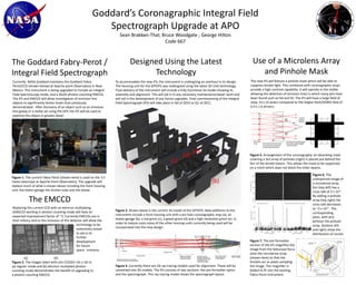
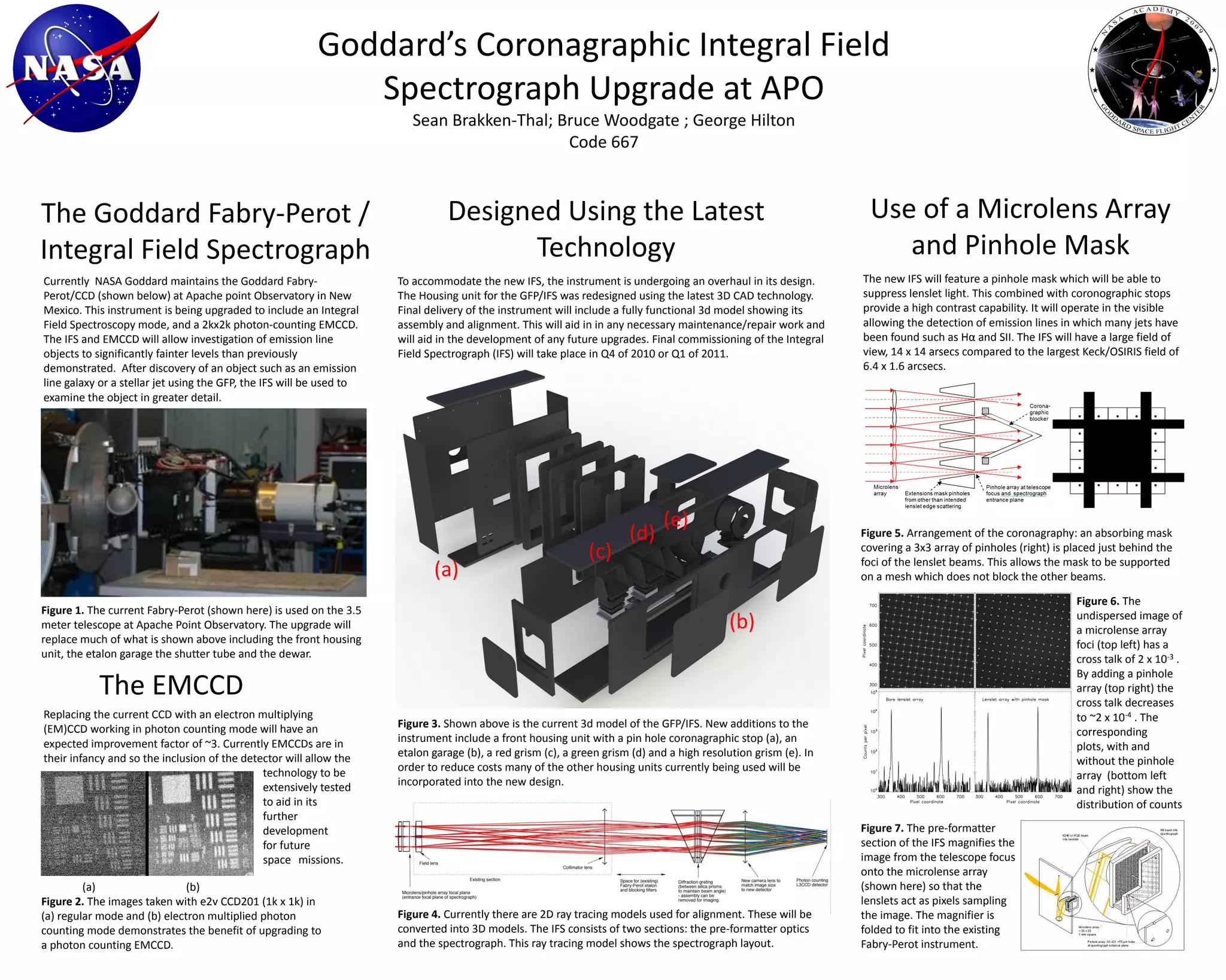
The Goddard Fabry-Perot/Integral Field Spectrograph at Apache Point Observatory is being upgraded to include an integral field spectroscopy mode and a new EMCCD detector. The upgrade will allow investigation of fainter emission line objects. The IFS will have a larger field of view than similar instruments and will use a pinhole mask to provide high contrast imaging. Final commissioning is planned for late 2010 or early 2011.
2024: Domino Containers - The Next Step. News from the Domino Container commu...
Goddard's Coronagraphic IFS Upgrade
1. Goddard’s Coronagraphic Integral Field Spectrograph Upgrade at APO Sean Brakken-Thal; Bruce Woodgate ; George Hilton Code 667 Use of a MicrolensArray and Pinhole Mask Designed Using the Latest Technology The Goddard Fabry-Perot / Integral Field Spectrograph The new IFS will feature a pinhole mask which will be able to suppress lenslet light. This combined with coronographic stops provide a high contrast capability. It will operate in the visible allowing the detection of emission lines in which many jets have been found such as Hα and SII. The IFS will have a large field of view, 14 x 14 arsecs compared to the largest Keck/OSIRIS field of 6.4 x 1.6 arcsecs. Currently NASA Goddard maintains the Goddard Fabry-Perot/CCD (shown below) at Apache point Observatory in New Mexico. This instrument is being upgraded to include an Integral Field Spectroscopy mode, and a 2kx2k photon-counting EMCCD. The IFS and EMCCD will allow investigation of emission line objects to significantly fainter levels than previously demonstrated. After discovery of an object such as an emission line galaxy or a stellar jet using the GFP, the IFS will be used to examine the object in greater detail. To accommodate the new IFS, the instrument is undergoing an overhaul in its design. The Housing unit for the GFP/IFS was redesigned using the latest 3D CAD technology. Final delivery of the instrument will include a fully functional 3d model showing its assembly and alignment. This will aid in in any necessary maintenance/repair work and will aid in the development of any future upgrades. Final commissioning of the Integral Field Spectrograph (IFS) will take place in Q4 of 2010 or Q1 of 2011. (e) (d) Figure 5. Arrangement of the coronagraphy: an absorbing mask covering a 3x3 array of pinholes (right) is placed just behind the foci of the lenslet beams. This allows the mask to be supported on a mesh which does not block the other beams. (c) (a) Figure 6. The undispersed image of a microlense array foci (top left) has a cross talk of 2 x 10⁻³ . By adding a pinhole array (top right) the cross talk decreases to ~2 x 10⁻⁴ . The corresponding plots, with and without the pinhole array (bottom left and right) show the distribution of counts Figure 1. The current Fabry-Perot (shown here) is used on the 3.5 meter telescope at Apache Point Observatory. The upgrade will replace much of what is shown above including the front housing unit, the etalon garage the shutter tube and the dewar. (b) The EMCCD Replacing the current CCD with an electron multiplying (EM)CCDworking in photon counting mode will have an expected improvement factor of ~3. Currently EMCCDs are in their infancy and so the inclusion of the detector will allow the technology to be extensively tested to aid in its further development for future space missions. Figure 3. Shown above is the current 3d model of the GFP/IFS. New additions to the instrument include a front housing unit with a pin hole coronagraphic stop (a), an etalon garage (b), a red grism (c), a green grism(d) and a high resolution grism (e). In order to reduce costs many of the other housing units currently being used will be incorporated into the new design. Figure 7. The pre-formatter section of the IFS magnifies the image from the telescope focus onto the microlense array (shown here) so that the lenslets act as pixels sampling the image. The magnifier is folded to fit into the existing Fabry-Perot instrument. (a) (b) Figure 2. The images taken with e2v CCD201 (1k x 1k) in (a) regular mode and (b) electron multiplied photon counting mode demonstrates the benefit of upgrading to a photon counting EMCCD. Figure 4. Currently there are 2D ray tracing models used for alignment. These will be converted into 3D models. The IFS consists of two sections: the pre-formatter optics and the spectrograph. This ray tracing model shows the spectrograph layout.