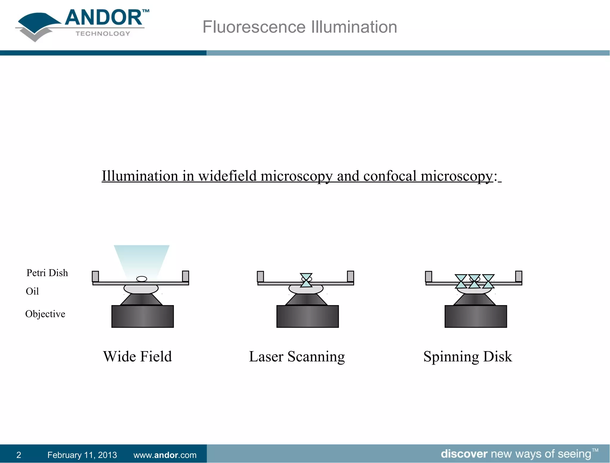
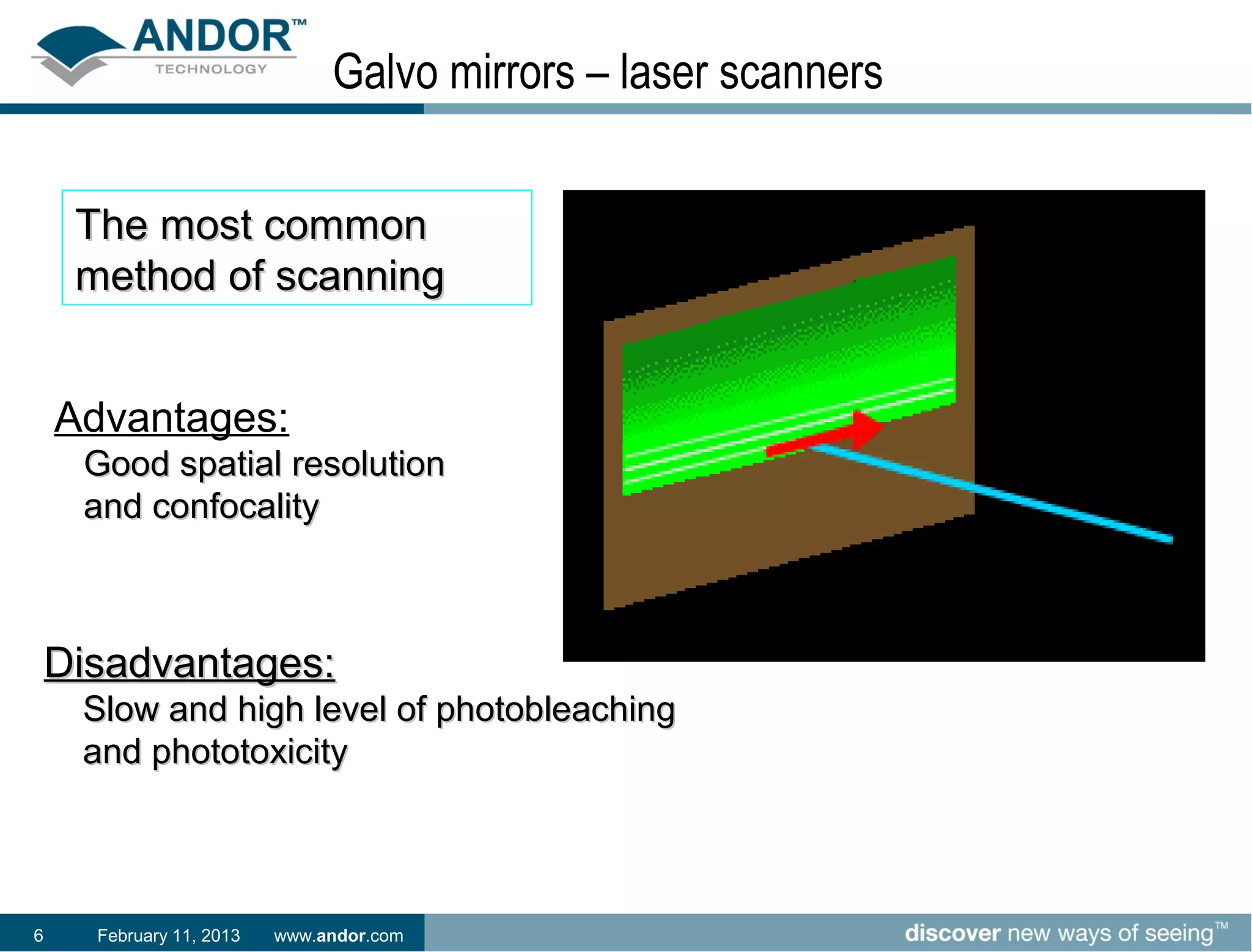
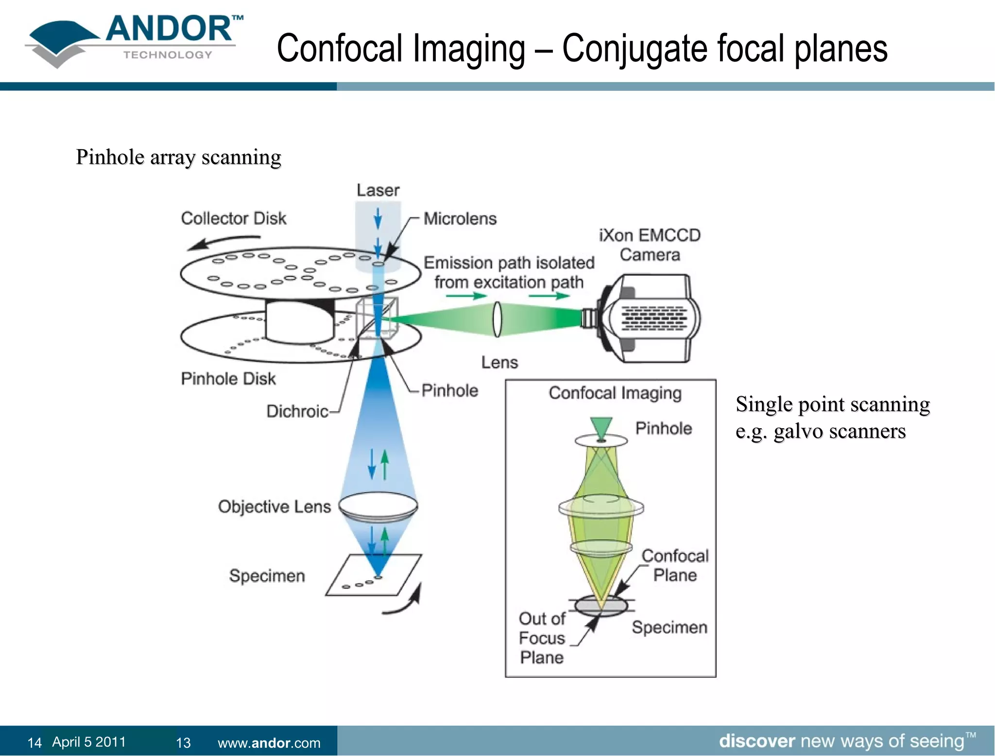
This document discusses laser-based dual spinning disk confocal microscopy technology. It describes how traditional confocal microscopy uses a single laser focused through a pinhole to scan samples, while dual spinning disk confocal microscopy uses two disks containing pinholes that spin to rapidly scan multiple points across a sample simultaneously, improving speed and light efficiency. The dual spinning disk technique, paired with a sensitive EMCCD camera, provides fast, high signal-to-noise live cell and multi-dimensional imaging while reducing photobleaching and phototoxicity compared to traditional laser scanning confocal microscopy.
This document discusses light microscopy detectors. It compares different types of detectors including PMTs, APDs, CCDs, and CMOS, noting their strengths and weaknesses in terms of speed, noise levels, resolution, and other factors. It focuses on how detectors can be optimized for sensitivity, discussing parameters like quantum efficiency and noise floor. Specific detector technologies are examined in more detail, such as EMCCDs and scientific CMOS cameras, comparing their performance and applications in areas like single molecule detection and live cell imaging.
This document discusses the development of a high-speed single-photon camera. It motivates the need for cameras with both extreme sensitivity and high speeds to enable applications like fluorescence correlation spectroscopy (FCS). The camera uses an array of single-photon avalanche diode (SPAD) detectors integrated on a CMOS chip. Each pixel contains circuitry to independently count and time photons with microsecond resolution at frame rates over 100,000 frames per second. The camera has been used for applications demonstrating sub-Rayleigh imaging and high-throughput FCS.
The document describes the MultiView 2000, a scanning probe microscope that allows for both tip and sample scanning. It has two scanning plates - one for the tip and one for the sample - allowing flexibility in experimental setup. Modes include near-field optical microscopy, atomic force microscopy, and confocal microscopy. Resolution is below 5nm laterally and 1nm vertically. It can image a variety of samples and integrate with optical microscopes.
This document describes the capabilities of the FIB-Nanotomography facility at the Centre Interdisciplinaire de Microscopie Electronique (CIME) at the École Polytechnique Fédérale de Lausanne (EPFL). The facility contains a Zeiss NVision 40 dual beam FIB/SEM that allows for the automated acquisition of large 3D volumes with voxel sizes down to 5-10nm. Examples are given of its applications in materials science, including the reconstruction of microstructures in superconducting cables and solder joints. The facility is also used for life science applications such as serial sectioning of brain tissue to reconstruct neuronal structures at nanoscale resolution. Automated segmentation techniques are applied to
Computed Radiography and digital radiographyDurga Singh
This document provides an overview of a seminar on Computed Radiography (CR) and Digital Radiography (DR). CR involves capturing x-ray data digitally using an imaging plate, which stores radiation exposure information that is later read out by a laser and processed into an image. DR directly converts x-rays to a digital signal using a detector connected to a computer. The seminar discusses the components, principles, workings, advantages and disadvantages of each technology. It describes how CR imaging plates use photostimulated luminescence and how digital images are produced during plate reading.
This document discusses optical lithography and the challenges of achieving high resolution for integrated circuit fabrication. It covers the lithography process, the role of lithography in IC fabrication, and resolution challenges like diffraction. It then describes several lithography methods used today or under development to improve resolution, including proximity lithography, contact lithography, projection lithography, phase-shifting masks, immersion lithography, and extreme ultraviolet lithography (EUVL). The document focuses on EUVL and the associated challenges of mask design and multilayer optics required for EUV wavelengths. It concludes with a section on simulating an EUV lithography system.
The document discusses a phosphorimager, which is an instrument that uses phosphor screens and laser scanning to detect and quantify radioactivity on samples like DNA, RNA, proteins, and tissues. It absorbs radiation from samples and stores the information as latent images on the phosphor screen. A laser then stimulates the screen to emit light proportional to the radioactivity, allowing the image to be captured digitally and analyzed. Phosphor imaging provides advantages over film methods like faster exposure times, greater sensitivity, and a wider dynamic range.
Viewing and recording the fluoroscopic imageSHASHI BHUSHAN
The document describes the process of viewing and recording intensified fluoroscopic images. It discusses how an image intensifier converts visual light images into electrical signals that are then viewed on a video monitor or recorded. Recording can be done using spot film cameras, cinefluoroscopy movie cameras, or by recording the video signal from the television camera onto magnetic tape, discs, or optical discs. The television camera converts the light image back into an electrical video signal for viewing, storage, or transmission to other viewing locations.
Computed radiography (CR) uses reusable imaging plates and associated hardware and software to acquire and display digital x-ray images as an alternative to traditional film-based radiography. The document provides an overview of the key components of a CR system, including the imaging plate, reader/digitizer, and workstation. It describes how a latent image is captured and stored in the phosphor plate from x-ray exposure, then stimulated and converted to a digital image by the reader using a laser. The advantages of CR over conventional radiography are also summarized, such as reusability of plates and improved image manipulation, storage and sharing capabilities.
Computed radiography AND ITS ADVANTAGESFirdousDar4
Computed radiography (CR) is a form of digital radiography that records x-ray images on photostimulable phosphor plates rather than conventional film. When the phosphor is exposed to x-rays, it absorbs the radiation energy and stores a latent image. Later, stimulating the phosphor with a laser or light source causes it to emit light in proportion to the absorbed x-ray exposure, allowing the image to be detected electronically and digitally processed. The CR plate is housed in a cassette similar to conventional film and read by a scanner that converts the emitted light into a digital image. Compared to conventional radiography, CR offers advantages like multiple viewings of images and easier image sharing, but also
Fluoroscopy is a form of real-time radiographic imaging used to guide procedures. It was invented in 1896 by Thomas Edison. Modern fluoroscopy uses image intensifiers or flat panel detectors to convert x-rays into visible light images. Digital systems have replaced conventional film-based fluoroscopy. Fluoroscopy provides real-time imaging but also exposes patients and staff to radiation, so dose reduction techniques must be used such as automatic brightness control, collimating to the area of interest, and minimizing unnecessary images and magnification.
This document summarizes Ramesh Raskar's work on coded computational photography. It describes using coded exposure to enable motion deblurring from a single photo in 2006. It also describes using a coded aperture to enable full resolution digital refocusing from a single photo in 2007 and using it for glare reduction in 2008. Additionally, it discusses using optical heterodyning to capture a 4D light field from a 2D sensor and single photo in 2007, as well as coding illumination and spectrum for applications like motion capture and acquiring an agile wavelength profile. The document outlines a progression from epsilon to coded to essence photography.
This document discusses fluoroscopy and the components of a fluoroscopy system. It describes how fluoroscopy allows real-time visualization of organ motion, contrast agents, stent placement, and catheterization. It then provides details on the evolution of fluoroscopy technology over time, from early fluoroscopes to modern image intensifiers and closed-circuit television systems. Key components like the image intensifier tube, video camera, and television monitor are explained. Methods of image recording like spot film devices and video recording are also summarized.
Rad 206 p05 Fundamentals of Imaging - Fluoroscopysehlawi
college of health sciences, fundamentals of imaging, image formation, radiography, radiologic, radiologic science, radiologic technologist, university of bahrain
This is a presentation I gave about MEMS processing at Tyndall in 2008. It goes over the various fabrication possibilities at Tyndall.
I personally like slide 3 and 4 trying to hook the history of watch making in with MEMS fabrication. This drive to go smaller and smaller with watch making can also be seen in electronics. Coincidentally, the first MEMS device was a time-keeping pendulum.
Fundamentals of Imaging. This course will provide you with the principles involved in the formation and recording of the radiologic image in both conventional and digital imaging systems as well as the principles of image quality assessment.
Part 4
ASC 3D is a 3D camera semiconductor company founded in 1987 that designs semiconductors, lasers, optics, and 3D Flash LIDAR cameras. It has multiple patents granted and several more pending. Its unique 3D Flash LIDAR technology can generate real-time 3D images and depth maps without motion distortion for applications such as autonomous vehicles, drones, industrial automation, and more. The technology offers advantages over other 3D solutions such as being lightweight, eye-safe, and not requiring moving parts.
This document provides an overview of digital radiography. It discusses the history, general principles, detectors, advantages, and disadvantages of digital radiography. Digital radiography was first developed in 1980 and makes radiographic images digitally stored and viewable on computers. The document focuses on the two main types of detectors used: flat panel detectors and high-density line-scan solid state detectors. Flat panel detectors can be indirect, using a scintillator, or direct, converting x-rays directly into charge. Digital radiography provides benefits like instant viewing, less radiation dose, and ability to share images digitally, but has higher costs than traditional radiography.
Icam 2009 Soft Actuators H Bridges Nanoporesdickbroer
This document discusses using photopolymerization of liquid crystal (LC) networks as a tool for micro- and nanostructuring. LC networks can be patterned and made responsive to form soft actuators for applications such as microfluidics, sensors, drug delivery, and artificial muscles. Examples are given of actuators that respond to temperature changes or UV light by contracting or expanding up to 2% with high modulus of 1GPa. LC networks provide a promising new tool for fabricating responsive materials and structures at the micro- and nanoscale.
The document summarizes the components and functioning of a fluoroscope. A fluoroscope uses an x-ray generator and tube to pass x-rays through a patient, and an image intensifier converts the remnant x-rays into visible light photons. This light image is detected by a television camera, which converts it into a video signal displayed on a monitor, allowing real-time visualization of internal structures and fluids. Spot films can also be taken as needed during fluoroscopic exams.
Thermal network cameras Performance considerations for intelligent videoAxis Communications
Thermal cameras have many advantages, such as allowing users to detect people, objects and incidents
in complete darkness and difficult conditions such as smoke, haze, dust and light fog. Eliminating the
need for flood lights, they reduce light pollution. In addition, a thermal camera is a reliable platform for
integrating intelligent software applications. A conventional network camera reacts to changes in the
captured image and can, for example, be disturbed by shades and back lighting. A thermal network
camera detects the thermal radiation from the object, which is a more static parameter compared to
visual changes in an image.
Microscopy dental applications /certified fixed orthodontic courses by Indian...Indian dental academy
Welcome to Indian Dental Academy
The Indian Dental Academy is the Leader in continuing dental education , training dentists in all aspects of dentistry and offering a wide range of dental certified courses in different formats.
Indian dental academy has a unique training program & curriculum that provides students with exceptional clinical skills and enabling them to return to their office with high level confidence and start treating patients
State of the art comprehensive training-Faculty of world wide repute &Very affordable.
The document discusses atomic force microscopy (AFM) and scanning tunneling microscopy (STM) techniques for nanoscale characterization, including a history of their development, operating principles, imaging modes, commercial applications, and examples of AFM tip fabrication methods and molecular imaging. It provides technical details on topics like non-contact dynamic mode AFM, carbon nanotube tips, and single-molecule force recognition events measured with AFM.
Introduction to digital radiography and pacsRad Tech
The document provides an overview of digital radiography and picture archiving and communication systems (PACS). It defines digital imaging and describes the processes of conventional radiography, computed radiography, and direct and indirect digital radiography. PACS are defined as networked systems that store and allow access to digital images in DICOM format from multiple locations. Early adoption of PACS and digital standards helped facilities share images between systems.
Digital radiography systems have replaced analog film-based systems. There are several types of digital radiography including computed radiography, scanned projection radiography, and indirect and direct digital radiography. Computed radiography uses a photostimulable phosphor plate to capture x-rays and a laser scanner to read the plate digitally. Scanned projection radiography functions similar to a CT scanner to produce digital radiographic images. Indirect and direct digital radiography use detectors like CCDs or photodiodes coupled with scintillators to directly convert x-rays to digital signals. Digital radiography allows for post-processing of images and reduces need for film and processing.
1. Fluoroscopy uses x-rays to provide real-time images of internal body structures and motion. Early fluoroscopes consisted of an x-ray tube, table, and faint fluorescent screen viewed in a dark room.
2. The development of the image intensifier in the 1950s allowed for brighter fluoroscopic images. Image intensifiers use a photocathode, electrostatic lens, and output phosphor to amplify the x-ray image thousands of times.
3. Modern fluoroscopy uses cesium iodide and silver screens, along with high voltage electron acceleration, to produce bright, minimally distorted images that can be viewed on monitors or recorded with video cameras.
This document analyzes transistor sizing and folding techniques to mitigate soft errors caused by radiation. It begins with an introduction to single event effects caused by radiation sources like cosmic rays. It then examines a 3D NMOSFET device and different ion profiles including alpha particles, copper and krypton. It evaluates increasing transistor widths to increase the critical charge of nodes using electric-level simulations. However, this does not capture the effect of increased device geometry on ion interactions. Therefore, device-level simulations are conducted showing collected charge increases with symmetric transistor sizing but peak pulse worsens. Further symmetric sizing simulations are recommended to see if recovery occurs.
Stanford Engineering Professor Olav Solgaard describes how optical fibers can be used to provide a crisp, three-dimensional window into human anatomy at a cellular level.
This document summarizes a new technique for x-ray imaging using a consumer grade digital SLR camera and reusable storage phosphor plates. It finds that the resolution of x-ray images captured with this method is comparable to laser scanning of storage phosphor plates. Additionally, this allows for portable and low-cost x-ray imaging. However, the sensitivity is still relatively low and needs further improvement. Future work includes additional field testing of the technique.
1) The document discusses OCT technology, including its principles and history of development. OCT uses low coherence interferometry to perform high-resolution cross-sectional imaging of biological tissues.
2) Time-domain OCT was initially developed but newer Fourier-domain OCT provides faster acquisition speed and higher resolution.
3) The document reviews various clinical applications of OCT in ophthalmology, including imaging of the retina, glaucoma, cornea, and cataracts. Common scanning patterns and what can be observed are described for retinal and glaucoma examination.
This document describes research on fabricating biological microspheres using inkjet printing and laser transfer methods. It finds that inkjet printing works well for low viscosity materials to form monodisperse, encapsulated microspheres, while laser transfer works for high viscosity materials. The size and distribution of the microspheres can be controlled by adjusting parameters like material concentration and laser fluence. Future work aims to better control microsphere size and uniformity for applications in drug delivery, tissue engineering, and stem cell studies.
The document discusses the history and development of micro-optics manufacturing from the 19th century to present day. Key developments include the use of microlenses in color photography in the 1920s, the application of semiconductor manufacturing techniques to micro-optics starting in the 1960s, and the current trend toward wafer-level micro-optics processing and packaging. SUSS MicroOptics is highlighted as a leading supplier of high-quality micro-optics manufactured using 8-inch wafer technology.
The document discusses potential future works building upon the research presented in the book. It describes how a wide field of view imaging system with polarization sensitivity could enable applications in security, robot navigation, and endoscopy. It also discusses how improving the angular resolution and developing algorithms to calculate distance traveled could allow for real-time material classification, navigation, and sun position detection for autonomous agents.
The document discusses potential future works building upon the research presented in the book. It proposes:
1) Developing a wide-field of view imaging system with polarization sensitivity that could enable applications like security, robot navigation, and endoscopy.
2) Creating a high angular resolution imaging system with polarization sensitivity that could provide more accurate polarization measurements and material classification in real-time.
3) Enhancing navigation algorithms by computing distance traveled in addition to direction from polarized light, allowing egocentric navigation computations on-chip.
Fast Access to More Detail, Better Insight & Accurate Analysis Using High Re...Esri
The document discusses using high resolution satellite imagery to provide fast access to more detail, better insight, and accurate analysis. It describes how local tasking of satellites through facilities like the European Direct Access Facility (EDAF) allows for detailed imaging planning, incorporation of real-time weather data, and higher success rates for cloud-free imagery compared to no weather information or forecast files alone. Local tasking provides flexibility and optimized collection plans for satellites like WorldView-2.
This document discusses Omnisens' DITEST system for distributed fiber optic leak detection. It summarizes that DITEST uses a single laser source and Brillouin scattering techniques to monitor thousands of locations along a single optical fiber with high sensitivity. DITEST offers long-range monitoring over 50km with 1m spatial resolution and temperature/strain measurement resolution of 0.5°C and 10mε. It provides continuous, real-time leak detection along pipelines with quick response times and no false alarms. DITEST is presented as offering significant advantages over alternative leak detection methods through its stability, sensitivity, scalability and lack of ongoing operational costs.
This document outlines a student project to develop a system to detect non-metallic weapons on passengers at airports using infrared light and image processing. The student aims to enhance airport security by detecting hidden plastic guns. The project proposes using a CCD sensor and infrared light to create digital images that can then be analyzed using particle analysis tools to identify threats. Initial testing showed some success in detecting plastic objects but identified challenges around orientation, lighting, and distance that need further refinement.
Keywords: Signal processing, Applied optics, Computer graphics and vision, Electronics, Art, and Online photo collections
A computational camera attempts to digitally capture the essence of visual information by exploiting the synergistic combination of task-specific optics, illumination, sensors and processing. We will discuss and play with thermal cameras, multi-spectral cameras, high-speed, and 3D range-sensing cameras and camera arrays. We will learn about opportunities in scientific and medical imaging, mobile-phone based photography, camera for HCI and sensors mimicking animal eyes.
We will learn about the complete camera pipeline. In several hands-on projects we will build several physical imaging prototypes and understand how each stage of the imaging process can be manipulated.
We will learn about modern methods for capturing and sharing visual information. If novel cameras can be designed to sample light in radically new ways, then rich and useful forms of visual information may be recorded -- beyond those present in traditional protographs. Furthermore, if computational process can be made aware of these novel imaging models, them the scene can be analyzed in higher dimensions and novel aesthetic renderings of the visual information can be synthesized.
In this couse we will study this emerging multi-disciplinary field -- one which is at the intersection of signal processing, applied optics, computer graphics and vision, electronics, art, and online sharing through social networks. We will examine whether such innovative camera-like sensors can overcome the tough problems in scene understanding and generate insightful awareness. In addition, we will develop new algorithms to exploit unusual optics, programmable wavelength control, and femto-second accurate photon counting to decompose the sensed values into perceptually critical elements.
Ramesh Raskar is an associate professor at the MIT Media Lab who researches computational photography. Some of his work includes using varying exposures in video to preserve high frequencies and combat motion blur. He has also developed techniques like image destabilization that use lens and sensor motion to programmably control defocus blur. Raskar aims to advance computational photography to enable high-level scene understanding through techniques like capturing depth from arrays of virtual cameras in LCD screens.
The PLOTS spectroscope is a cheap ($10) device that boasts good resolution, is easy to buld and has applications in a number of areas. This slide show was put together for a workshop at the South Australian Science Teachers annual conference 2013. It details how to build the spectroscope, install the software and outlines many uses for it in education. It provides links to the main PLOTS site, where a non-profit version of the scope is being sold and the software developed.
This document discusses compressive displays and related technologies for reducing the bandwidth requirements of multi-view and light field displays. It describes several technologies including layered 3D displays, polarization field displays, and high-rank 3D displays that decompose 4D light fields into lower dimensional representations. It also discusses using mathematical techniques like non-negative matrix factorization for further compressing display data. The document promotes open collaboration through the proposed Compressive Display Consortium to advance next generation displays.
Optical lithography moved to shorter wavelengths like deep ultraviolet (DUV) due to limitations of mercury lamps. Excimer lasers emitting at wavelengths like 248nm and 193nm were adopted as they met the requirements of high photon energy and shorter wavelengths. As feature sizes continued shrinking, even shorter wavelengths like extreme ultraviolet (EUV) at 13.5nm were needed. EUV lithography uses reflective optics since materials absorb at this wavelength, and requires operating in vacuum since all materials absorb EUV radiation. Key challenges for EUV include developing high power radiation sources, improving reflective mirror lifetimes against contamination, and developing suitable photoresists with low line edge roughness.
Traineeship Melbourne University - Michael BeljaarsMichael Beljaars
This document summarizes a student's research project investigating the use of nano-apertures to improve the spatial resolution of ion beam lithography. The student had difficulty milling nano-apertures in atomic force microscope cantilevers using a focussed ion beam, but was eventually able to use one successfully to mask a 1.5 MeV helium ion beam. The document also describes the background and motivation for the research, including limitations of current ion beam lithography techniques and how nano-aperture masking could help overcome these limitations to enable the creation of photonic crystals.
MEMS Pressure difference based GyroscopeNemish Kanwar
This document discusses the design and simulation of a thermal MEMS gyroscope. It begins with background on gyroscopes and different MEMS gyroscope designs, including tuning fork, vibrating wheel, and wine glass resonator designs. It then focuses on the design, modification, modeling, and COMSOL simulation of a thermal MEMS gyroscope. The simulation aims to analyze the effects of angular rate on the pressure difference of the thermal gyroscope design to evaluate its sensitivity and applicability. Further research is recommended to improve the simplified model and simulation.
Stevenson Eye Tracking With The Adaptive Optics Scanning Laser OphthalmoscopeKalle
Recent advances in high magnification retinal imaging have allowed for visualization of individual retinal photoreceptors, but these systems also suffer from distortions due to fixational eye motion. Algorithms developed to remove these distortions have the added benefit of providing arc second level resolution of the eye movements that produce them. The system also allows for visualization of targets on the retina, allowing for absolute retinal position measures to the level of individual cones. This paper will describe the process used to remove the eye movement artifacts and present analysis of their spectral characteristics. We find a roughly 1/f amplitude spectrum similar to that reported by Findlay (1971) with no evidence for a distinct
tremor component.
The document describes the parts and working of a polarizing microscope. It has optical components like polarizers, analyzers and lenses, and mechanical components like the rotating stage. Light from the specimen is polarized and its interaction with the optical components is used to identify properties of minerals and rocks. The polarized microscope allows examination of anisotropic materials and determination of their optical characteristics, which has applications in geology and mineral exploration.
1. Laser Based Dual Spinning Disk Technology
Andrew Hubbard
February 11, 2013 www.andor.com
2. Fluorescence Illumination
Illumination in widefield microscopy and confocal microscopy:
Petri Dish
Oil
Objective
Wide Field Laser Scanning Spinning Disk
2 February 11, 2013 www.andor.com
3. The confocal principle …
Point Illumination, scanned
across specimen in raster format
Fluorescence is detected through
confocal pinhole aperture
Out-of focus information is rejected
by pinhole
Direct optical sectioning
w/o computation and assumptions
Best contrast and resolution
3 February 11, 2013 www.andor.com
4. How to create a confocal image
By moving the point of light
Raster the focussed point of laser across and down the
sample using one or two galvanometer driven mirrors
Not the fastest method of scanning, very popular
By moving the confocal pinholes
Use a spinning disk of pinholes to scan the light
Nipkow disk principle, very fast
4 February 11, 2013 www.andor.com
5. How to create a confocal image
By moving the point of light
Raster the focussed point of laser across and down the
sample using one or two galvanometer driven mirrors
Not the fastest method of scanning, very popular
By moving the confocal pinholes
Use a spinning disk of pinholes to scan the light
Nipkow disk principle, very fast
5 February 11, 2013 www.andor.com
6. Galvo mirrors – laser scanners
The most common
method of scanning
Advantages:
Good spatial resolution
and confocality
Single laser beam
Disadvantages:
Slow and high level of photobleaching
and phototoxicity
6 February 11, 2013 www.andor.com
7. Moving the point of light
“Classical Confocal” – the most
common method of scanning Galvo mirror scan
and photomultiplier
tube (PMT) detection
of fluorescence
7 February 11, 2013 www.andor.com
8. The Challenge of Live Cell Imaging
Key Parameters
Lateral resolution
Axial resolution
Temporal resolution
Low photobleaching
Low phototoxicity
Fast intra cellular trafficking events captured at high temporal resolution in a
region within a fibroblast cell. 3D rendered images made from 8 Z sections
with a 0.8 micron Z spacing. Each stack of images took 0.7 seconds to capture
and this was repeated over 90 seconds. The endosome in the middle is 3 microns
in diameter and it fuses with an endosome of 1 micron in diameter.
Data courtesy of Frode Skjeldal, who works in Professor Oddmund Bakkes lab
in the department of Molecular Biosciences at Oslo University.
8 February 11, 2013 www.andor.com
9. How to create a confocal image
By moving the confocal pinholes
Use a spinning disk of pinholes to scan the light
Nipkow disk principle, very fast
9 February 11, 2013 www.andor.com
10. The Nipkow disk – Petran 1968
It’s a
The first proposed Pinholes
MAMMOTH
method of scanning
Multi-point scanner
Advantages:
Fast, real time confocal
Disadvantages:
Historically - Poor light
efficiency through the disk
10 February 11, 2013 www.andor.com
11. Nipkow Spinning Disk
1-2%
Nipkow
disc with
pinholes
11 February 11, 2013 www.andor.com
12. Dual Spinning Disk (Yokogawa)
Collector
disc with
microlenses
70%
Nipkow
disc with
pinholes
12 February 11, 2013 www.andor.com
13. Dual Spinning Disk Technology
Real-Time
DichroicMovies
mirror
EMCCD
camera
13 February 11, 2013 www.andor.com
14. Confocal Imaging – Conjugate focal planes
Pinhole array scanning
Single point scanning
e.g. galvo scanners
14 April 5 2011 11, 2013
February www.andor.com
15. What makes a detector sensitive?
Two key parameters:
Quantum Efficiency
Noise
Camera must be designed to ensure these parameters
are optimised.
15 February 11, 2013 www.andor.com
16. Typical Quantum Efficiency – EM and I-CCD
BI CCD
100
Virtual Phase
90 FI CCD
Quantum Efficiency (%)
80
70 FI CCD
60 Gen III ICCD
50
40
30
20
10
0
200 300 400 500 600 700 800 900 1000
Wavelength (nm)
16 February 11, 2013 www.andor.com
17. Electron Multiplication – EM Gain
Low readout noise ~ 5-6 e rms
EM Readout noise ~ 45 e rms
Probability of Impact Ionization = p
Number of Gain register stages, n
Gain ~ (1+p) n
e.g. p=0.01, n=500, Gain = 145
p=0.015, n=500, Gain = 1,710
17 February 11, 2013 www.andor.com
18. Effect of EMCCD Gain on S/N
EMCCD Gain
Gain x1 Gain x10
Gain x100 Gain x500
18 February 11, 2013 www.andor.com
19. Benefits: It’s still ALIVE!
• Fast, real time confocal due
to multi point spinning disk
excitation and multi point
EMCCD detection
• Good S/N due to highly
sensitive EMCCD detection
• Reduced photobleaching
• Reduced phototoxicity
19 February 11, 2013 www.andor.com
20. XYZT imaging (4D)
Longterm 4d imaging of Zebrafish
embryo as it undergoes early cell
division. 192 Z sections were taken
with a step size of 0.3 micron. The
stack took 20 seconds to acquire
with an interval of 100 seconds
between stacks. This series of
maximum projection images is made
up from 51840 frames that were
acquired over a time period of ~9
hours.
20 February 11, 2013 www.andor.com
21. XYZTλ imaging (5D)
Key Parameters
Lateral resolution
Axial resolution
Temporal resolution
Spectral resolution
Low photobleaching
Low phototoxicity
Drosophila development, chromosomes in red,
tubulin in green. 5 z sections, 206 time points
21 February 11, 2013 www.andor.com
22. Dual Spinning Disk vs. Point Scanning
Point scanner vs. Dual Disk Scanner
LSCM CSU
No of points scanned 1 1000
Parallel detection No Yes
Detector PMT CCD/EMCCD
Detector QE ~30 % ~ 90%
Frame rate (Hz) @512x512 0.5 to 4 10 to 30
Laser power per point 50 to 80 uW 1 uW
Bleach rate Hi Low
Frame time skew Significant Low
Programmable scan pattern Yes No
Simultaneous Programmable scan Yes No
Pinhole Variable Fixed (50um)
22 April 5 2011 11, 2013
February www.andor.com
23. Photobleaching analysis
Spinning
Disk
Point
Scanning
Data from Wang et al, Journal of Microscopy, May 2005
23 February 11, 2013 www.andor.com
24. Limitations of Spinning Disk
Resolution
Fixed pinhole of SD is matched to high mag high NA objectives
24 February 11, 2013 www.andor.com
25. Limitations of Spinning Disk
Axial Resolution and Pinhole Crosstalk
•A question of balancing pinhole size and spacing for optimal
resolution, light efficiency and speed
•The distance between pinholes can be increased to improve the axial
resolution at the cost of signal
•Depending on staining pattern and localisation thick specimens can be
challenging
25 February 11, 2013 www.andor.com
26. Active Illumination
Bleaching
(e.g. Fluorescence Recovery After Photobleaching &
Fluorescence Loss In Photobleaching)
Photochemical destruction of a fluorophore with excessive
illumination
FRAP
Cell Compartmentalisation & Continuity
Protein dynamics and turnover
26 February 11, 2013 www.andor.com
27. FRAPPA
Rapidly raster scans the sample,
causing chemical changes to
fluorescent dyes.
Uses CW laser from Andor ALC.
Mainly used for
•FRAP – Fluorescent Recovery After Photobleaching
•PA –
Photoactivation/Photoconversion
FRAP + PA = FRAPPA
Used with the XD Spinning Disk
27 February 11, 2013 www.andor.com
28. CS
U
Laser from MPU/ALC
CS
U
Laser from MPU/ALC
28 February 11, 2013 www.andor.com
29. Thanks for your attention
29 February 11, 2013 www.andor.com
Editor's Notes
In a basic microscope with fluorescence illumination, the sample is bathed in light In confocal techniques the sample is illuminated with a focal spot of light which is required as part of the imaging technique. The focussed light is achieved by passing the light through a pinhole
* 07/16/96 * But, how does it work? Basically illumination via a laser source is passed through a pinhole. The light from the pinhole is focussed to a particular point in the sample. Light passing deeper into the sample (pale green line) causes fluorescence emission from the sample below the confocal plane. The light from this point does not pass back through the pinhole and the detector ignores it. Emitted light from the focussed point, at the confocal plane, passes in its entirety back through the pinhole and the detector uses it to form the image. Thus light from out of focus planes is discarded and does not form part of the image.
* 07/16/96 * By comparing these two methods of canning the confocal light.
* 07/16/96 *
* 07/16/96 * This cartoon shows the point of light rasterring across and down the sample. Each point of emitted light passes back through the confocal pinhole and is detected on a photomultiplier tube. The PMT then converts the photons into electrons and ultimately an image formed from grey levels is displayed on a computer screen. These systems are very good in resolution, but they may bleach the sample quickly or kill living samples very quickly.
* 07/16/96 * A good example of an application where a point scanner would struggle. Endosome fusion. The larger endosome is 3 microns in diameter and fuses with the smaller one. Crucial parameters here are in red, the resolution has to be good to see such small endosomes, the system needs to be fast to acquire the stack in under a second, and the sample cannot bleach or die as this is imaged for 90 seconds. Temporal Resolution may or may not be important depending on the biology being investigated.
* 07/16/96 * By comparing these two methods of canning the confocal light.
* 07/16/96 * The principle of imaging confocally using multiple pinholes came before the now popular point scanning confocal microscopes.
* 07/16/96 * Back in Petran’s day the disk threw away 98% of the excitation light, this proved to be a major hurdle especially with insensitive detection.
* 07/16/96 * So a second disk was introduced, this one containing microlenses. Each lens focuses the light, which is now a laser source, through its pinhole. This increase the throughput of the scanning mechanics up to 70%. This increase in transmission across the pinholes means spinning disk systems can be used for imaging low fluorescent label expressing, delicate living biology.
The emitted light from the sample is detected back through the pinholes, so all is confocal, and the photons sent to the ultra sensitive iXon camera. The iXon detects the photons and converts to electrons, the image is displayed in real time on the computer screen and movies of dynamic living biology can be made at high resolution and sensitivity.
* 07/16/96 * So the Revolution spinning disk confocal, with its method of scan and superior low light detection capability means the researcher can capture biological events as they happen with minimal damage to both the fluorescent molecules and the sample itself. Because the light delivered to the sample is of a ‘low intensity, high frequency’ dose (the laser is dispersed into many micro-lasers, 1000 beams in fact, and then scanned very fast, 1000 times a second), effects of photo bleaching and photo toxicity are reduced. Further benefits in these two crucial points can be achieved as the iXon EMCCD is so sensitive the actual laser power used can be kept very low.
* 07/16/96 *
* 07/16/96 *
* 07/16/96 *
* 07/16/96 *
* 07/16/96 * With the low light levels that Spinning disk requires/utilizes, live cell imaging with good signal to noise and confocal resolution is possible.
* 07/16/96 * Now all the parameters are red (crucial) as in 5D imaging you also need good spectral resolution as you are imaging more than one colour. This is on the edge imaging and the demands on the technology are huge. If laser power is too high then cell division will be blocked, and if exposures are too long then events are missed.
* 07/16/96 * So the Revolution spinning disk confocal, with its method of scan and superior low light detection capability means the researcher can capture biological events as they happen with minimal damage to both the fluorescent molecules and the sample itself. Because the light delivered to the sample is of a ‘low intensity, high frequency’ dose (the laser is dispersed into many micro-lasers, 1000 beams in fact, and then scanned very fast, 1000 times a second), effects of photo bleaching and photo toxicity are reduced. Further benefits in these two crucial points can be achieved as the iXon is so sensitive the actual laser power used can be kept very low.
The Nipkow disk pinhole diameter in the figure (a) is assumed to be a single Airy pattern unit in diameter with reference to the focal plane (in effect, approximately 0.5 micrometers). It is also assumed that essentially all of the fluorescence emission representing the central maximum of the Airy disk represented by the point object proceeds through the pinhole and towards the objective. A view of the Nipkow disk from the side opposite the objective is presented in (b), and the pinhole diameter ( D ; 0.5 micrometers) and inter-pinhole spacing ( S ; 2.5 micrometers) are indicated on the drawing. The total light transmission through a disk having a D/S ratio of 1/5 is approximately 4 percent, consistent with typical spinning disk microscopes that are not equipped with microlens arrays. Relocating the specimen point approximately 1 micrometer beneath the focal plane (c) reduces the amount of light passing through the pinhole due to the fact that much of the light emanating from the point now strikes the bottom of the disk (d) and is reflected from the surface. Relocating the specimen point to a distance equal to S (2.5 micrometers) away from the focal plane enables some of the emission light to pass through the first ring of neighboring pinholes (e) and (f). As a result, more fluorescence emission now passes through the six peripheral pinholes than through the central pinhole, mimicking the background signal haze for a highly fluorescent point source positioned away from the focal plane in a thick specimen. Note that when the specimen point is positioned at the location in (e), emission light is now spread over a much larger diameter on the Nipkow disk and the excitation is likewise diminished. As the specimen point is lowered still farther away from the focal plane, the number of photons passing through the disk continues to diminish until some of the emission light begins to pass through the ring of secondary neighbours when the point is approximately 5 micrometers beneath the disk.
In most cases photobleaching is avoided in live cell imaging as previously discussed. However, targetted photobleaching can be used to further understand the physiology of a cell.