This document provides an introduction to technical rescue training. It outlines the schedule, objectives, safety rules, and content for a 48-hour Introduction to Technical Rescue course. The course covers topics such as NFPA standards, equipment, knots, anchors, belay systems, and lowering systems. It aims to teach the minimum skills required to perform technical rescue operations according to NFPA 1006 standards. Safety is emphasized as being paramount for the inherently dangerous nature of technical rescue work.


![Specific information will be placed in all four quadrants of the Main Entrance "X" summarizing the entire
search of the structure.
• The left quadrant is for the Rescue Team Identifier.
• The top quadrant is for the date and time the search was completed.
• The right quadrant is for any significant hazards located in the structure.
• The bottom quadrant is for the number of "LIVE" or "DEAD" victims still inside the structure. Use a
“0” in the bottom quadrant if no victims are inside the structure.
X
GA-TF1
LEFT QUADRANT - Task Force identifier
X
7/15/07
1400 hr
TOP QUADRANT - Time and date that the Task Force personnel left the
structure.
XRATS RIGHT QUADRANT - Personal hazards.
X
2 - LIVE
3 - DEAD
BOTTOM QUADRANT - Number of live and dead victims still inside the
structure. ["0" = no victims]
During the search function, while inside the structure, a large single slash shall be made upon entry of
each room or area. After the search of the room or area has been completed a second large slash shall be
drawn in the opposite direction forming an "X". The only information placed in any of the "X" quadrants
while inside the structure shall be that pertaining to any significant hazards or the number of "LIVE" or
"DEAD" victims.
As with the Structure/Hazards Evaluation, it is important that markings are made specific to each area of
entry or separate part of the building. If an area is searched and no victims are found, it must be noted with
GFA Technical Rescue: 3-in-1 Student Manual
Approved Curriculum Feb 2010 35](https://image.slidesharecdn.com/technicalrescue-230122110858-10ae76e4/85/Technical-Rescue-pdf-35-320.jpg)


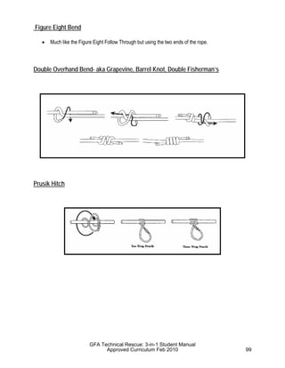
![“A knot… is either exactly right or it is hopelessly wrong.”
--Clifford W. Ashley
Knots are a key link in Rope Rescue Systems. Rescuers should frequently practice and develop efficient
knot tying skills until they can tie knots in the dark, when cold, and tired. Tying knots should be a skill that
is proficient and automatic. A knot is most frequently the weakest part of a system even when properly
tied. Therefore an improperly tied knot or incorrect choice of knot could result in system failure. Knots
should be standardized so everyone on the team can readily identify and easily perform system safety
checks.
Knot Terminology
A Knot [or tie] is a fastening, including bights, bends and hitches, made by tying together lengths
of rope or webbing is a prescribed way. (NFPA 1006 - 3.3.90)
Types of Knots or Ties:
• ___________ A tie that remains in place
• ___________ A tie that joins two ropes or rope ends
• ___________ A tie that attaches or wraps around an object
to remain in place. When the object is removed, the tie will
fall apart.
• Back-up Knot (also called a safety knot) - A second knot
used to secure the tail of a primary knot; also known as a safety or keeper.
Parts of a knot:
1. ________________ formed by simply bending the rope back on itself, keeping the
sides parallel
2. ________________ formed by crossing one side of a bight over the other
3. ________________ formed by further bending one side of a loop, keeping both
sides parallel similar to the bight
Finer Points of Knot Tying
A knot should be compact, neat and well dressed. The bight should be large enough to
accommodate whatever is going into the bight. Practice with the same size rope that you would use during
GFA Technical Rescue: 3-in-1 Student Manual
Approved Curriculum Feb 2010 93](https://image.slidesharecdn.com/technicalrescue-230122110858-10ae76e4/85/Technical-Rescue-pdf-93-320.jpg)


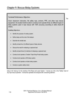


![Exterior leaning ladders can be used to provide a high help above a window, or opening, to facilitate the removal of a
victim from an upper floor that is accessible with a ground ladder. The ladder is placed above the window or point of
departure and a directional pulley is affixed via a webbing bridle secured to the beams of the ladder. The belay should be
anchored in a position at or above the point of departure. The ladder can be tied off or footed by at least 2 rescuers,
depending on the intent and duration of the operation.
Interior leaning ladders can be used in situations where ground ladders will not reach the position above the point of
departure. These ladders will be leaned against the header of the window or point of departure and a directional pulley is
affixed via a webbing bridle secured to the beams of the ladder. The belay should be anchored in a position at or above
the point of departure. The ladder can be tied off or footed by at least 2 rescuers, depending on the intent and duration of
the operation. The angle of the ladder will dictate the kick-out force of the ladders base.
Cantilever ladders and Ladder Jibs are used in situations where the victim’s location is further than ground ladders will
reach and the use of an interior leaning ladder is not feasible. This incorporates the use of the ladder as a lever and
requires that the ladder be AT LEAST 14 FEET IN LENGTH. The tip of the ladder is rigged with a webbing bridle and
high directional pulley. The tip is then placed outside the window or over the roof edge. NO MORE THAN 1 RUNG
FROM THE EDGE OF THE SUPPORTING STRUCTURE TO THE BRIDLE is extended over the edge. A 6:1 ratio is
used for the weight at the base of the ladder compared to the load at the tip. (if the load is 300# - the ladder base is 12
feet from the edge [fulcrum] with the bridle 2 feet out past the edge = 6:1 IMA. You will need at least 300# at the base of
the ladder to counterbalance the load.)
Some “alternative” uses for Fire Service ladders – Taken from Rescue Systems I Student Manual 1996
GFA Technical Rescue: 3-in-1 Student Manual
Approved Curriculum Feb 2010 203](https://image.slidesharecdn.com/technicalrescue-230122110858-10ae76e4/85/Technical-Rescue-pdf-203-320.jpg)


![BACKGROUND
Number of Workers Killed
No detailed national data are available on
the number of workers killed each year by
contact with uncontrolled hazardous energy.
However, during the period 1982–1997,
NIOSH investigated 1,281 fatal incidents as
part of their FACE Program. Of these, 152
involved installation, maintenance, service,
or repair tasks on or near machines, equip-
ment, processes, or systems. Because the
FACE program was active in only 20 States
between 1982 and 1997, these fatalities
represent only a portion of the U.S. workers
who were killed by contact with uncon-
trolled hazardous energy.
Contributing Factors
Review of these 152 incidents suggests
that three related factors contributed to
these fatalities:
•Failure to completely de-energize, iso-
late, block, and/or dissipate the energy
source (82% of the incidents, or 124 of
152)
•Failure to lockout and tagout energy
control devices and isolation points af-
ter de-energization (11% of the inci-
dents, or 17 of 152)
•Failure to verify that the energy source
was de-energized before beginning
work (7% of the incidents, or 11 of 152)
In a study conducted by the United Auto
Workers (UAW), 20% of the fatalities (83 of
414) that occurred among their members
between 1973 and 1995 were attributed to
inadequate hazardous energy control pro-
cedures— specifically, lockout/tagout pro-
cedures. The energy sources involved in
these fatalities included kinetic, potential,
electrical, and thermal energy [UAW
1997].
CURRENT OSHA
REGULATIONS
Current Occupational Safety and Health
Administration (OSHA) standards for
general industry are established to pre-
vent injuries and fatalities from contact with
hazardous energy [29 CFR*
1910.147].
This standard requires employers to “
es-
tablish a program consisting of energy con-
trol procedures, employee training and
periodic inspections to ensure that before
any employee performs any servicing or
maintenance on a machine or equipment
where the unexpected energizing, start up
or release of stored energy could occur
and cause injury, the machine or equip-
ment shall be isolated from the energy
source, and rendered inoperative.”
Other OSHA standards for general industry
cite the need for de-energizing electrical
energy and locking and tagging electrical
circuits and equipment before performing
maintenance and servicing tasks. The fol-
lowing OSHA standards contain lock-
out/tagout-related requirements:
1910.146 Permit-Required Confined
Spaces
1910.177 Servicing Multi-Piece and
Single Piece Rim Wheels
1910.178 Powered Industrial Trucks
1910.179 Overhead and Gantry
Cranes
*Code of Federal Regulations. See CFR in
references.
2 Hazardous Energy
Student Manual Appendix Material
Information gathered from various resources](https://image.slidesharecdn.com/technicalrescue-230122110858-10ae76e4/85/Technical-Rescue-pdf-277-320.jpg)
![1910.181 Derricks
1910.213 Woodworking Machinery
1910.217 Mechanical Power
Presses
1910.218 Forging Machines
1910.261 Pulp, Paper, and
Paperboard Mills
1910.262 Textiles
1910.263 Bakery Equipment
1910.265 Sawmills
1910.269 Electric Power
Generation, Transmission,
and Distribution
1910.272 Grain Handling
1910.305 Wiring Methods,
Components, and
Equipment for General Use
1910.306 Specific Purpose
Equipment and
Installations
1910.333 Selection and Use of Work
Practices
OSHA standards for construction also con-
tain requirements for protecting workers
from electrical hazards [29 CFR 1926.416
and 29 CFR 1926.417]. These standards
require that workers exposed to any part of
an electrical power circuit be protected
through de-energizing and grounding of
the circuit or through appropriate guarding.
These standards also require that all
de-energized circuits be rendered inopera-
ble and tagged out.
FORMS OF HAZARDOUS
ENERGY
Workers may be exposed to hazardous
energy in several forms and combinations
during installation, maintenance, service,
or repair work. A comprehensive hazard-
ous energy control program should ad-
dress all forms of hazardous energy
[NIOSH 1983]:
•Kinetic (mechanical) energy in the
moving parts of mechanical systems
•Potential energy stored in pressure
vessels, gas tanks, hydraulic or pneu-
matic systems, and springs (potential
energy can be released as hazardous
kinetic energy)
•Electrical energy from generated elec-
trical power, static sources, or electri-
cal storage devices (such as batteries
or capacitors)
•Thermal energy (high or low temperature)
resulting from mechanical work, radia-
tion, chemical reaction, or electrical
resistance
CASE REPORTS
As part of the FACE Program from 1982
through 1997, NIOSH investigated 152
fatal incidents in which workers contacted
uncontrolled hazardous energy. The follow-
ing case reports summarize five of these
investigations.
Case No. 1— Uncontrolled Kinetic
Energy
A 25-year-old male worker at a concrete
pipe manufacturing facilitydied from injuries
Hazardous Energy 3
Student Manual Appendix Material
Information gathered from various resources](https://image.slidesharecdn.com/technicalrescue-230122110858-10ae76e4/85/Technical-Rescue-pdf-278-320.jpg)
![he received while cleaning a ribbon-type
concrete mixer. The victim’
s daily tasks
included cleaning out the concrete mixer at
the end of the shift. The clean-out procedure
was to shut off the power at the breaker
panel (approximately 35 feet from the mixer),
push the toggle switch by the mixer to
make sure that the power was off, and then
enter the mixer to clean it.
No one witnessed the event, but investiga-
tors concluded that the mixer operator had
shut off the main breaker and then made
a telephone call instead of following the
normal procedure for checking the mixer
before anyone entered it. The victim did not
know that the operator had de-energized
the mixer at the breaker. Thinking he was
turning the mixer off, he activated the
breaker switch and energized the mixer.
The victim then entered the mixer and be-
gan cleaning without first pushing the tog-
gle switch to make sure that the equipment
was de-energized. The mixer operator re-
turned from making his telephone call and
pushed the toggle switch to check that
the mixer was de-energized. The mixer
started, and the operator heard the victim
scream. He went immediately to the main
breaker panel and shut off the mixer.
Within 30 minutes, the emergency medical
service (EMS) transported the victim to a
local hospital and then to a local trauma
center. He died approximately 4 hours later
[NIOSH 1995].
Case No. 2— Uncontrolled
Electrical Energy
A 53-year-old journeyman wireman was
electrocuted when he contacted two
energized, 6.9 -kilovolt buss terminals. The
victim and two coworkers (all contract
employees) were installing electrical
components of a sulfur dioxide emission
control system in a 14-compartment switch
house.
The circuit breaker protecting the internal
buss†
within the switch house had been
tripped out and marked with a tag— but it
had not been secured by locking. This pro-
cedure was consistent with the hazardous
energy control procedures of the power
plant.
The victim and his coworkers were wiping
down the individual compartments before a
prestartup inspection by power plant per-
sonnel. Without the knowledge of the vic-
tim and his coworkers, power plant
personnel had energized the internal buss
in the switch house. When the victim began
to wipe down one of the compartments at
the south end of the switch house, he con-
tacted the A-phase buss terminal with his
right hand and the C-phase buss terminal
with his left hand. This act completed a
path between phases, and the victim was
electrocuted.
A coworker walking past the victim during
the incident was blown backward by the
arcing and received first-degree flash
burns on his face and neck. A second
coworker at the north end of the switch
house heard the explosion and came to
help. He notified the contractor’
s safety co-
ordinator by radio and requested EMS.
The EMS responded in about 15 minutes
and transported the victim to a local hospi-
tal emergency room where he was pro-
nounced dead [NIOSH 1994].
†A conducting bar, rod, or tube that carries heavy
currents to supply several electric circuits.
4 Hazardous Energy
Student Manual Appendix Material
Information gathered from various resources](https://image.slidesharecdn.com/technicalrescue-230122110858-10ae76e4/85/Technical-Rescue-pdf-279-320.jpg)
![Case No. 3— Uncontrolled Kinetic
Energy
A 38-year-old worker at a county sanitary
landfill died after falling into a large trash
compactor used to bale cardboard for
recycling. The cardboard was lifted 20 feet
by a belt conveyor and fed through a 20-
by 44-inch opening into a hopper. The
hopper had automatic controls that acti-
vated the baler when enough material col-
lected in the baling chamber. When the
baler was activated, material in the cham-
ber was compressed by a ram that entered
the chamber from the side. Excess mate-
rial above the chamber was trimmed by a
shearer.
On the day of the incident, cardboard
jammed at the conveyor discharge open-
ing. Without stopping, de-energizing, or
locking out the equipment, the victim rode
the conveyor up to the discharge opening
to clear the jam. He fell into the hopper and
the baling cycle was automatically acti-
vated, amputating his legs. The victim bled
to death before he could be removed from
the machine [Colorado Department of Pub-
lic Health and Environment 1994].
Case No. 4— Uncontrolled
Potential Energy
The 32-year-old owner of a heavy equip-
ment maintenance business died after a
wheel and tire assembly exploded during
repair work. The victim was removing the
assembly from a test roller when it ex-
ploded and struck him with the flying split
rim of the wheel.
The test roller was a large, two-wheeled
cart that carried about 60,000 pounds of
concrete weights. The roller was used in
highway construction to test road surfaces
for proper compaction.
The victim had been working as a subcon-
tractor to repair the wheel and tire assem-
bly, which had been smoking earlier in the
day and was believed to be rubbing against
the concrete weights. The assembly con-
sisted of a two-piece outside rim and an in-
side ring retainer that was held together
and mounted on the axle by 20 wheel bolts
and nuts. Normal air pressure for the mounted
tire was 70 psi.
The victim raised and blocked the roller.
Without discharging the air from the tire
and using no personal protective equip-
ment, he began to remove the wheel nuts
using a pneumatic impact wrench. He had
no training or experience with this type of
work or in the servicing of this type of
wheel. He did not realize that only some of
the bolts held the wheel tire assembly to
the axle. The remainder held the outer half
of the rim to the inside half, securing the tire
to the wheel. As the victim removed the
nineteenth wheel nut, the pressurized air in
the tire discharged explosively, causing the
split rim to fly off the wheel and strike him.
He died from cerebral contusions and lac-
erations [Minnesota Department of Health
1992].
Case No. 5— Uncontrolled Kinetic
and Thermal Energy
A 33-year-old janitorial worker died after
he was trapped inside a linen dryer at a
hospital laundry while cleaning plastic
debris from the inside of the dryer drum.
The cleaning task (which usually took
15 minutes to an hour) involved propping
open the door to the dryer with a piece of
wood and entering the 4- by 8-foot dryer
drum. The melted debris was removed by
scraping and chiseling it with screwdrivers
and chisels. The dryer was part of an auto-
mated system that delivered wet laundry
from the washer through an overhead
Hazardous Energy 5
Student Manual Appendix Material
Information gathered from various resources](https://image.slidesharecdn.com/technicalrescue-230122110858-10ae76e4/85/Technical-Rescue-pdf-280-320.jpg)
![conveyor to the dryer, where it was dried
during a 6-minute cycle with air tempera-
tures of 217Eto 230EF. The system control
panel was equipped with an error light that
was activated if the dryer door was open,
indicating that the dryer was out of service.
On the night of the incident, the victim
propped the door open and entered the
dryer drum without de-energizing or
locking out the dryer. He began to clean
the inside of the drum. Although the error
light had been activated when the door
was propped open, the signal was
misinterpreted by a coworker, who restarted
the system. When the system was re-
started, the overhead conveyor delivered a
200-pound load of wet laundry to the
dryer— knocking out the wooden door prop,
trapping the victim inside, and automatically
starting the drying cycle. The victim re-
mained trapped inside until the cycle was
completed and was discovered when the
load was discharged from the dryer. He
died thirty minutes later of severe burns
and blunt head trauma [Massachusetts
Department of Public Health 1992].
CONCLUSIONS
Review of the NIOSH FACE data indicates
that three related factors contribute to in-
juries and deaths that occur when workers
perform installation, maintenance, service,
or repair work near hazardous energy
sources:
•Failure to completely de-energize, iso-
late, block, and/or dissipate the haz-
ardous energy source
•Failure to lockout and tagout energy
control devices and isolation points af-
ter the hazardous energy source has
been de-energized
•Failure to verify that the hazardous en-
ergy source was de-energized before
beginning work
These fatalities could have been prevented
if comprehensive hazardous energy con-
trol procedures had been implemented
and followed.
RECOMMENDATIONS
NIOSH recommends that employers im-
plement the following steps to prevent inju-
ries and deaths of workers who must work
with hazardous energy in their jobs:
1. Comply with OSHA regulations.
2. Develop and implement a hazardous
energy control program.
3. Identify and label all hazardous energy
sources.
4. De-energize, isolate, block, and/or dis-
sipate all forms of hazardous energy
before work begins.
5. Establish lockout/tagout programs that
— require workers to secure energy
control devices with their own indi-
vidually assigned locks and
keys— only one key for each lock
the worker controls;‡
‡Use of master keys should be reserved for un-
usual circumstances when the worker is absent
from the workplace. However, if master keys are
necessary, keep them under supervisory control.
List the proper procedures for using them in the
written program for controlling hazardousenergy.
6 Hazardous Energy
Student Manual Appendix Material
Information gathered from various resources](https://image.slidesharecdn.com/technicalrescue-230122110858-10ae76e4/85/Technical-Rescue-pdf-281-320.jpg)

![• Lockout and tagout all energy-isolating
devices to prevent inadvertent or unau-
thorized reactivation or startup.
• Isolate, block, and/or dissipate all haz-
ardous sources of stored or residual
energy, including those in adjacent
equipment.
• Before beginning to work, verify energy
isolation and de-energization, includ-
ing that in adjacent equipment or en-
ergy sources.
• After work is complete, verify that all
personnel are clear of danger points
before re-energizing the system.
Hazardous energy control among work
groups must be coordinated when multiple
employers are involved in large projects
and when shift changes occur during such
activities. Outside contractors should work
with the facility owner to make sure that an
adequate hazardous energy control pro-
gram is implemented specifically for con-
tract workers.
3. Identify and label all hazardous
energy sources.
Employers should use jobsite surveys to
ensure that all hazardous energy sources
(including those in adjacent equipment)
are identified before beginning any in-
stallation, maintenance, service, or repair
tasks. Hazardous energy includes mechan-
ical motion, potential or stored energy, elec-
trical energy, thermal energy, and chemical
reactions. Energy-isolating devices such as
breaker panels and control valves should
be clearly labeled [NIOSH 1983].
4. De-energize, isolate, block, and/or dis-
sipate all forms of hazardous energy.
All forms of hazardous energy should be
de-energized, isolated, blocked, and/or
dissipated before workers begin any instal-
lation, maintenance, service, or repair
work. The method of energy control de-
pends on the form of energy involved and
the available means to control it. Energy is
considered to be isolated or blocked
when its flow or use cannot occur
[NIOSH 1983].
To isolate or block energy, take the follow-
ing steps:
• Disconnect or shut down engines or
motors that power mechanical systems.
• De-energize electrical circuits by dis-
connecting the power source from the
circuit.
• Block fluid (gas, liquid, or vapor) flow in
hydraulic, pneumatic, or steam sys-
tems by using control valves or by cap-
ping or blanking§
the lines.
• Block machine parts against motion
that might result from gravity (falling).
Some forms of energy must also be dissi-
pated after a system has been
de-energized. System components such
as electrical capacitors, hydraulic accumu-
lators, or air reservoirs may retain sufficient
energy to cause serious injury or
death— even though the component has
been de-energized, isolated, or blocked
from the system and locked out.
Energy can be dissipated by taking the fol-
lowing steps:
•Vent fluids from pressure vessels, tanks,
or accumulators until internal pressure
§Lines can be blanked by inserting a solid plate be-
tween the flanges of a joint.
8 Hazardous Energy
Student Manual Appendix Material
Information gathered from various resources](https://image.slidesharecdn.com/technicalrescue-230122110858-10ae76e4/85/Technical-Rescue-pdf-283-320.jpg)
![is at atmospheric levels. However, do
not vent vessels or tanks containing
toxic, flammable, or explosive substances
directly to the atmosphere.
•Discharge capacitors by grounding.
•Release or block springs that are un-
der tension or compression.
•Dissipate inertial forces by allowing
the system to come to a complete
stop after the machine or equipment
has been shut down and isolated from
its energy sources.
5. Establish lockout/tagout programs
requiring individually assigned
locks and keys to secure energy
control devices.
Lockout/tagout programs should be based
on the principle of only one key for each
lock the worker controls.**
This means the
following:
— Workers are assigned individual
locks operable by only one key for
use in securing energy control de-
vices (breaker panels, control
valves, manual override switches,
etc.).
— Each worker maintains custody of
the key for each of his or her as-
signed locks.**
**Use of master keys should be reserved for un-
usual circumstances when the worker is absent
from the workplace. However, if master keys are
necessary, keep them under supervisory control.
List the proper procedures for using them in the
written program for controlling hazardousenergy.
— Each lock is labeled with a durable
tag or other means that identifies
its owner.
— When work is performed by more
than one worker, each worker
applies his or her own lock to the
energy-securing device. Scissors-
type hasps made of hardened
steel are available to facilitate the
use of more than one lock to se-
cure an energy control device.
— All de-energized circuits and sys-
tems are clearly labeled with dura-
ble tags.
— The worker who installs a lock is
the one who removes it after all
work has been completed [NIOSH
1988].
— If work is not complete when the
shift changes, workers arriving on
shift apply their locks before depart-
ing workers remove their locks.
Because tags can be easily removed, they
are not a substitute for locks. Workers are
safest with a program that uses both locks
and warning tags to prevent systems from
being inadvertently re-energized [NIOSH
1988].
6. Verify that all energy sources are
de-energized before work begins.
Employers should establish and enforce
company policies requiring workers to
verify that all energy sources are
de-energized before work begins. This verifi-
cation should ensure that all energy sources
(including stored energy) are controlled
(that is, de-energized, isolated, blocked,
and/or dissipated) before work begins. Ap-
propriate testing equipment should be re-
quired as needed.
Hazardous Energy 9
Student Manual Appendix Material
Information gathered from various resources](https://image.slidesharecdn.com/technicalrescue-230122110858-10ae76e4/85/Technical-Rescue-pdf-284-320.jpg)
![7. Inspect repair work before re-
energizing the equipment.
To ensure that equipment will operate as
expected when it is re-energized, em-
ployers should require qualified persons to
inspect completed installation, mainte-
nance, service, or repair work. The inspec-
tion should verify that installation, repairs,
and modifications were performed cor-
rectly and that the correct replacement
parts were used. When equivalent or up-
dated parts must be substituted for original
parts, the system may need to be modified.
Re-energized equipment should be closely
monitored for several operating cycles to
ensure that it is functioning correctly and
safely.
8. Make sure that all persons are clear
of danger points before re-energizing
the system.
Employers should develop procedures to
verify that all persons are clear of danger
points before re-energizing the system.
Locks and tags should be removed only by
the workers who installed them— and only
after workers have been cleared from the
danger points. This may require visual in-
spections and searches of areas around
machinery or electrical circuits to assure
that workers will not be exposed to the re-
lease of hazardous energy when equip-
ment is re-energized. Workers should be
informed about impending equipment
start-up with warning devices they can see
and hear. Such devices will help assure
that workers are clear before equipment is
re-energized.
9. Train workers in the basic concepts
of hazardous energy control.
Employers should train ALL workers in
the basic concepts of hazardous energy
control, including energy isolation,
locking and tagging of control devices, ver-
ifying de-energization, and clearing danger
points before re-energizing equipment.
Workers whose duties involve installation,
maintenance, service, or repair work
should be trained in the detailed control
procedures required for their particular
equipment. This training should enable
workers to identify tasks that might expose
them to hazardous energy and the effec-
tive methods for its control.
10. Include a hazardous energy control
program with any confined-space
entry program.
When work requires entry into confined
spaces such as utility vaults or tanks, em-
ployers should incorporate a hazardous
energy control program as part of their
confined-space entry program— according
to OSHA standards [29 CFR 1910.146 and
1910.147] and published NIOSH guide-
lines [NIOSH 1979, 1987].
11. Design machines and systems that
make it easy to control hazardous
energy.
Employers should encourage manufactur-
ers to design control valves, switches, and
equipment that are easy to access and
lockout.
ACKNOWLEDGMENTS
Principal contributors to this Alert were
Paul Moore and Tim Pizatella of the NIOSH
Division of Safety Research (DSR). Injury
data were provided by the Health and
Safety Department, International Union,
United Auto Workers (UAW). Cases pre-
sented in this Alert were contributed by
Georjean Madery, formerly of the Minne-
sota Department of Health; Lyle McKenzie,
Colorado Department of Health; and Jon
10 Hazardous Energy
Student Manual Appendix Material
Information gathered from various resources](https://image.slidesharecdn.com/technicalrescue-230122110858-10ae76e4/85/Technical-Rescue-pdf-285-320.jpg)
![Lifvergren, formerly of the Massachusetts
Department of Health. Stephanie Pratt,
DSR, provided data analysis, and Larry
Reed, Division of Physical Sciences and
Engineering, provided many helpful com-
ments and suggestions. Dwayne Smith,
formerly of DSR, provided the first working
draft of this Alert.
Please direct comments, questions, or re-
quests for additional information to the fol-
lowing:
Dr. Nancy A. Stout, Director
Division of Safety Research
National Institute for Occupational Safety
and Health
1095 Willowdale Road
Morgantown, West Virginia 26505–2888
Telephone: 304–285–5894; or call
1–800–35–NIOSH (1–800–356–4674).
We greatly appreciate your help in protect-
ing the safety and health of U.S. workers.
Linda Rosenstock, M.D., M.P.H.
Director, National Institute for
Occupational Safety and Health
Centers for Disease Control and
Prevention
REFERENCES
CFR. Code of Federal regulations. Wash-
ington, DC: U.S. Government Printing Of-
fice, Office of the Federal Register.
Colorado Department of Public Health and
Environment [1994]. Thirty-eight-year-old
recycling technician dies as a result of inju-
ries sustained when he fell into a cardboard
compactor. Denver, CO: Colorado Depart-
ment of Health and Environment, Colorado
Fatality Assessment and Control Evalua-
tion (FACE) Report No. 94CO029.
Massachusetts Department of Public
Health [1992]. Custodian dies in a confined
space in a hospital laundry. Boston, MA:
Massachusetts Department of Public
Health, Massachusetts Fatality Assess-
ment and Control Evaluation (MA FACE)
Report No. 91–02.
Minnesota Department of Health [1992].
Owner of heavy equipment maintenance
business dies after being struck by an
exploding split rim of a test roller tire.
Minneapolis, MN: Minnesota Department of
Health, Minnesota Fatality Assessment and
Control Evaluation (MN FACE) Report
No. MN9208.
NIOSH [1979]. Criteria for a recommended
standard: working in confined spaces.
Morgantown, WV: U.S. Department of
Health, Education, and Welfare, Public
Health Service, Center for Disease Con-
trol, National Institute for Occupational
Safety and Health, DHEW (NIOSH) Publi-
cation No. 80–106.
NIOSH [1983]. Guidelines for controlling
hazardous energy during maintenance
and servicing. Morgantown, WV: U.S. De-
partment of Health and Human Services,
Public Health Service, Centers for Disease
Control, National Institute for Occupational
Safety and Health, DHHS (NIOSH) Publi-
cation No. 83–125.
NIOSH [1987]. A guide to safety in confined
spaces. Morgantown, WV: U.S. Depart-
ment of Health and Human Services, Pub-
lic Health Service, Centers for Disease
Control, National Institute for Occupational
Hazardous Energy 11
Student Manual Appendix Material
Information gathered from various resources](https://image.slidesharecdn.com/technicalrescue-230122110858-10ae76e4/85/Technical-Rescue-pdf-286-320.jpg)
![Safety and Health, DHHS (NIOSH) Publi-
cation No. 87–113.
NIOSH [1988]. NIOSH testimony on the
Occupational Safety and Health Adminis-
tration’
s proposed rule on the control of
hazardous energy sources (lockout/tagout),
September 8, 1988, OSHA Docket
No. S–012A. Cincinnati, OH: U.S. Depart-
ment of Health and Human Services, Pub-
lic Health Service, Centers for Disease
Control, National Institute for Occupational
Safety and Health.
NIOSH [1994]. Journeyman wireman elec-
trocuted after contacting energized
switchgear components at power
plant— West Virginia. Morgantown, WV:
U.S. Department of Health and Human
Services, Public Health Service, Centers
for Disease Control and Prevention,
National Institute for Occupational Safety
and Health, Fatality Assessment and Con-
trol Evaluation (FACE) Report No. 94–10.
NIOSH [1995]. Laborer fatally injured while
cleaning concrete mixer— Tennessee.
Morgantown, WV: U.S. Department of
Health and Human Services, Public Health
Service, Centers for Disease Control and
Prevention, National Institute for Occupa-
tional Safety and Health, Fatality Assess-
ment and Control Evaluation (FACE)
Report No. 95–12.
UAW [1997]. An analysis of trends in fatal
injuries related to lock-out failure in
UAW-represented worker populations.
Detroit MI: International Union, United Au-
tomobile, Aerospace and Agricultural Im-
plement Workers of America— UAW, UAW
Health and Safety Department.
12 Hazardous Energy
Student Manual Appendix Material
Information gathered from various resources](https://image.slidesharecdn.com/technicalrescue-230122110858-10ae76e4/85/Technical-Rescue-pdf-287-320.jpg)

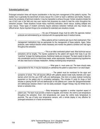
![ICS MAP/CHART DISPLAY SYMBOLOGY
MINIMUM RECOMMENDED
Proposed Boom
BLACK
Completed Boom
X X X Absorbent Material
10
RED Aug 9 Hazard Origin
1430
Incident Command Post
Incident Base
HOLT Camp (Identify by Name)
REDFERN
Staging Area (Identify by Name)
BLUE Joint Information Center
Helispot (Location & Number)
Helibase
Mobile Relay
OPTIONAL
Police Station
Telephone
Fire Station
BLUE Mobile Weather Unit
Emergency Operations Center
Fire Aid Section
Hospital
ORANGE
Oil Spread Prediction
BLACK Actual Oil or
Chemical Plume
[I] [I I] Branches (Initially numbered
clockwise from Incident origin)
(A) (B) Divisions (Initially lettered clockwise
from Incident origin)
BLACK Division Boundary
Branch Boundary
W/10 1600 9/7 Wind Speed and Direction
Safety/Security Zone
Boat Ramp
TO BE USED ON INCIDENT BRIEFING AND ACTION PLAN
MAPS/CHARTS
1
EOC
P
T
F
X
B
C
R
JIC
H
1 hr
4 hr
5 hr
3 hr
2 hr
1
S
All overlays must contain
registration marks. These
may consist of identified road
intersections township/range
coordinates, map corners etc.
Student Manual Appendix Material
Information gathered from various resources](https://image.slidesharecdn.com/technicalrescue-230122110858-10ae76e4/85/Technical-Rescue-pdf-289-320.jpg)


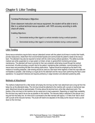
![2) Front (stomach or chest) rather than rear (back) harness lanyard
attachment points will aid uninjured workers in self-rescue. This is
crucial if workers are not closely supervised.
3) Any time a worker must spend time hanging in a harness, a harness
with a seat rather than straps alone should be used to help position the
upper legs horizontally.
4) A gradual arrest device should be employed to lessen deceleration
injuries.
5) Workers should get supervised (because this is dangerous) experience
at hanging in the harness they will be using. [OHS endbug]
Bill Weems (bweems@ccs.ua.edu) and Phil Bishop are at the University of
Alabama, in Tuscaloosa, Ala. Dr. Weems is an industrial hygienist. He
directs Safe State, the OSHA consultation agency for small business in
Alabama. Dr. Bishop is an ergonomist. He teaches and conducts research in
the physiology of human performance.
Reference
Seddon, Paul. Harness Suspension: review and evaluation of existing
information. Health and Safety Executive. Research Report 451/2002. 104
pp.
Pull quotes:
All personnel should be trained that suspension in an upright condition for
longer than five minutes can be fatal.
Depending on the harness attachment point and the position of the worker’s
body at arrest, different harness attachments offer different advantages.
Fall victims can slow the onset of suspension trauma by pushing down
vigorously with the legs, by positioning their body in a horizontal or slight
leg-high position, or by standing up.
Student Manual Appendix Material
Information gathered from various resources](https://image.slidesharecdn.com/technicalrescue-230122110858-10ae76e4/85/Technical-Rescue-pdf-314-320.jpg)