The document discusses several networking concepts:
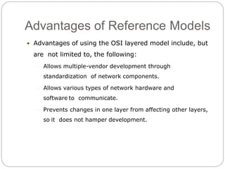
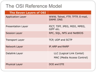
- The OSI reference model created standardized layers for networking.
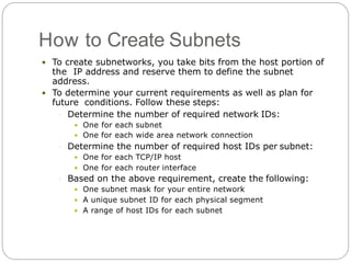
- Subnetting networks optimizes performance by dividing large networks into smaller logical subnets. Methods for determining subnet masks and allocating addresses are covered.
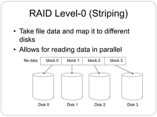
- RAID (redundant array of independent disks) systems provide data redundancy and improved performance through techniques like disk striping, mirroring, and parity. The various RAID levels trade off these properties differently.
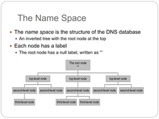
- Active Directory and DNS are protocols for centralized network management and translation of names to network addresses respectively. DHCP dynamically allocates IP addresses to devices on a network. IOPS is a metric for storage performance.