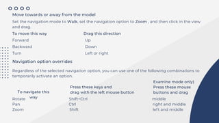
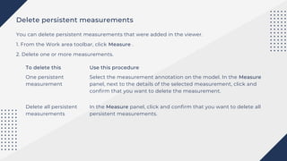
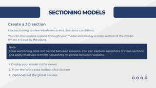
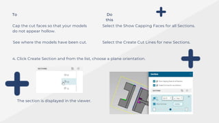
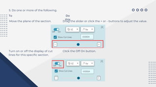
OVERVIEW
OF
VISUALIZIN
G 3D
PRODUCTS
Based on your business needs, the administrator may disable the viewer from loading the
model when the model is opened. This is useful when loading large assemblies. You can choose to
view specific parts by selecting items from the tree, or use the All On command in the Visibility
Controls list to view the entire model
1. Search for and open a part or an assembly that has associated 3D model (JT) data.
2. Click the 3D tab to display the model in the viewer.
You will receive a warning if you load a session file that contains unresolved NGID references. If
this happens, load the session file into Lifecycle Visualization and resolve the broken links.
Open a 3D
model
3D VIEWER MODES AND OPTIONS
Setting mouse navigation modes and options
On systems with mouse pointing devices, you can navigate the 3D view of a model in either of two
navigation modes:
Note:
Mouse navigation modes and options are not available with Base Visualization.
Examine In the Examine mode, navigation acts as if you were holding the model at a point
in the center of the screen. This is the default navigation mode.
Note:
Your administrator can change the mouse's zoom behavior in Examine mode from
Push (default) to Pull. When set to Push, zoom in by pushing the mouse or scrolling
the mouse wheel away from you. When set to Pull, zoom in by pulling the mouse or
scrolling the mouse wheel towards you.
Walk In the Walk mode, navigation acts as if you are moving relative to the model.
The Walk mode is particularly useful when you want to navigate through a large model.
From the Work area toolbar, click Viewer Options .
In the Viewer Options panel, under NAVIGATION, select a mode.
Navigation options for the Examine and Walk modes include Rotate , Pan , and Zoom .
Navigate geometry using a mouse
You can drag a mouse pointer to navigate the view of a 3D model. While navigating by dragging,
the cursor appearance changes to show the active navigation mode and option.
The following descriptions are for a two-button mouse with a scroll wheel that can be pressed to
act as a middle (tertiary) mouse button.
Position the model in the viewer
To position this
way
Do
this
Center a part in the view
Fit the selected parts in
the view
Point to a location on the part and click the scroll wheel.
From the Work area toolbar, click Visibility Controls > Fit.
Note:
The viewer fits the selected parts in the view even if part visibility is
turned off.
If no parts are selected, all parts for which visibility is turned on are
fit into the view.
Rotate the view
Set the navigation option to Rotate , and then click within the view and drag.
You can rotate freely or constrain the rotation. The initial cursor location determines the rotation axis
To rotate freely Before you drag, place the cursor
In the center of the viewer.
Examine mode freely rotates the model as if you were holding it at a point
in the center of the view.
Walk mode changes the view direction; if you move the cursor up, the
model slides down
While the navigation mode is Examine, the following constrained rotations are available only if Rotate
is the active option. When the navigation mode is Walk, the constrained rotations are always available
To constrain rotation this way Before you drag, place the cursor
Rotate around a horizontal axis Near the left or right edge of the viewer
Rotate around a vertical axis
Rotate around an axis that is
perpendicular to the center of
the view
Near the bottom edge of the viewer
Near the top edge of the viewer.
Pan the camera
Set the navigation option to Pan , and then click in the view and drag.
• In the Examine mode, the model moves in the same direction that you drag.
• In the Walk mode, the model moves in the direction opposite to the direction that you drag.
Zoom the model
Set the navigation mode to Examine, and then do either of the following.
• Roll the scroll wheel forward to zoom in. Roll the scroll wheel backward to zoom out.
Note:
Your administrator can change the mouse's zoom behavior in Examine mode from "Push"
(default) to "Pull." When set to "Push," zoom in by pushing the mouse or scrolling the mouse
wheel away from you. When set to "Pull," zoom in by pulling the mouse or scrolling the mouse
wheel towards you.
• Set the navigation option to Zoom , and then click in the view and drag. To zoom in, drag up, and
to zoom out, drag down.
Move towards or away from the model
Set the navigation mode to Walk, set the navigation option to Zoom , and then click in the view
and drag.
To move this way Drag this direction
Forward Up
Backward Down
Turn Left or right
Navigation option overrides
Regardless of the selected navigation option, you can use one of the following combinations to
temporarily activate an option.
To navigate this
way
Press these keys and
drag with the left mouse button
Examine mode only)
Press these mouse
buttons and drag
Rotate Shift+Ctrl middle
Pan Ctrl right and middle
Zoom Shift left and middle
Orient the view to a standard angle
You can orient the view of a 3D model to a standard angle.
• From the Work area toolbar, click Standard Views and select a view orientation
Orientatio
n
Perspective or alignment
Top Aligned to the Z-axis, facing in the –Z direction
Bottom Aligned to the Z-axis, facing in the +Z direction
Left Aligned to the X-axis, facing in the +X direction
Right Aligned to the X-axis, facing in the –X direction
Front Aligned to the Y-axis, facing in the +Y direction
Back Aligned to the Y-axis, facing in the –Y direction
+Isometric A 3/4 perspective, facing downward (+Isometric)
-Isometric A 3/4 perspective, facing upward (-Isometric)
The trihedron shows the global coordinate system X, Y, and Z axes. By default, the trihedron is
displayed.
To show or hide the trihedron, click Viewer Options . In the Viewer Options panel, click Trihedron
The trihedron state (shown or hidden) is saved across sessions
Note:
• Viewer Options are not available with Base Visualization
• The standard view orientation angles are defined by the following preferences. Your administrator
can modified these to meet your needs
The Front camera orientation
By default, this is set to +Y, which means the front view is the camera orientation aligned
to the Y-axis, facing in the +Y direction. The Back orientation is automatically set to the
opposite (-Y).
The Left camera orientation
By default, this is set to +X, which means the left view is the camera orientation aligned to the X-
axis, facing in the +X direction. The Right orientation is automatically set to the opposite (-X).
The Top camera orientation
By default, this is set to -Z, which means the top view is the camera orientation aligned to
the Z-axis, facing in the -Z direction. The Bottom orientation is automatically set to the
opposite (+Z).
Switch selection display mode
• To switch the selection display mode, from the Work area toolbar, click Use Transparency
Use Transparency active
Selected parts are shown in their original color and with
bounding boxes.
Unselected parts are shown as transparent.
You cannot select transparent parts by clicking them in the
viewer.
Use Transparency not active
Selected parts are shown in the highlight color.
Unselected parts are shown in their original colors.
You can select any displayed part by clicking it in the viewer.
You can turn off and turn on the display of assembly components (parts). You can set visibility in
two ways:
• In a component list, click the icon for a component to switch its visibility on or off.
You can switch the visibility status on and off regardless of the selection status.
• From the Work area toolbar, click Visibility Controls , and then click a command such as Context
Only. The availability of commands depends on the current selection and visibility state.
Hide or display components
Note:
You can also search for and filter components by volume or by proximity to target parts. Visibility
of matching parts is turned on, while that of non-matching parts is turned off.
Note:
Your administrator may disable the viewer from loading the model when the model is opened.
This is useful when loading large assemblies. You can choose to view specific parts by selecting
items from the tree, or use the All On command in the Visibility Controls list to view the
entire model.
FOCUSING ON COMPONENTS
Select components
• When you know where to find the component in the model, you can select the component in the
viewer.
• If you know the component name, you can select it by clicking the component name in a list such
as:
1. Results of an in-context search
2. Active structure list
3. List displayed when you click a separator in the navigation breadcrumb
To make this selection Do
this
Select a component In either the viewer or in a list, click or tap the component
Select all components
contained by the parent
assembly of a selected
component
In the viewer, click or tap a selected component.
Select an additional
component
To turn on multiselect mode and add a component to the selection,
do any of the following
With a mouse
• Click and hold the component.
• Hold Ctrl and click the component.
• In the active structure list, right-click the component.
Press and hold the component.
On a touch device
• Press and hold the component.
While multiselect mode is turned on, you can click or tap additional
components to add them to the selection
Select all components 1. Turn on multiselect mode.
With a mouse
• Click and hold a component.
• Hold Ctrl and click a component.
• In the active structure list, right-click a component.
Press and hold a component.
On a touch device
• Press and hold a component.
2. From the Work area toolbar, click Select All .
Deselect all
components
• Click or tap the viewer background.
• Click or tap the root of the breadcrumb.
Adjust the visibility of components
You can adjust the visibility of components based on the current selection. The visibility commands
appear in the Visibility Controls list from the Work area toolbar, as applicable for the current visibility
status and selection.
To do this From the Visibility Controls list, select this command
Zoom to fit components to the work area. Fit
Turn on the visibility of all components. All On
Turn off the visibility of all components. All Off
Turn on the visibility of the currently
selected components, and turn off the
visibility of unselected components.
Selected Only
Turn off the visibility of the selected Selected Off
components.
Turn on the visibility of the selected Selected On
components.
Turn off the visibility of the components included in
the end of the assembly structure breadcrumb (the
components shown in the active content list area)
Context
Off
Turn on the visibility of the components included in
the end of the assembly structure breadcrumb (the
components shown in the active content list area)
Context On
Turn off the visibility of components not included in
the end of the assembly structure breadcrumb (the
components shown in the active content list area)
Context
Only
Select the components included in the end of the
assembly structure breadcrumb (the components
shown in the active content list area)
Select Context
Selection status examples
Selection status and visibility settings affect the display of active content.
In the following display examples, Use Transparency is on
Nothing is selected.
All components are turned on.
Components have their original
coloring
The Bearing Large component is
selected.
All components are turned on.
All content except the selected
component is transparent.
The Bearing Large component is
selected.
All unselected content is turned
off.
The 140-f40001-7 component is
selected and turned off.
All unselected components are
turned on and transparent.
MEASURING 3D MODELS
Change the working unit of the Viewer
Use the Displayed dropdown list on the Viewer Options panel to change the working unit of the
Teamcenter X viewer. The selected unit becomes the default unit for performing quick
measurements,persisted measurements, sections, or volume and proximity. Linear measurement
values shown in the Query and Measure panels are converted to the displayed unit for new
measurements, however, existing measurements are based on the Displayed unit setting at the
time the measurement was taken.
1. Open your model or assembly in the viewer.
2. From the Work area toolbar, click Viewer Options .
3. Click the Displayed dropdown to select a new linear unit value from the list.
The value that displays in the Model field is the unit in which the model was created.
• If your model does not already contain measurement data, Quick Measure displays one
measurement at a time. You cannot move the quick measurement in the viewer, and the
measurement disappears when you begin another measurement or select another menu option.
• If your model already contains measurement data, Quick Measure adds persistent
measurements to your model.
Perform quick measurements in 3D models
You can use the Quick Measure command to measure between part features (points, vertices,
edges, faces or surfaces, and arc centers) or between parts in an assembly.
Note:
The default display unit is Meters. Your administrator can configure a different default unit.
Note:
Quick measurement is not available when the Measure or the Query command is active.
1. Open your model or assembly in the viewer.
2. From the Work area toolbar, click Quick Measure .
Next to Quick Measure , the current selection mode appears: Pick Parts or Pick Features .
3. If you want to change the selection mode, click Pick Parts or Pick Features .
4. Click the first part or feature, and then click the second part or feature.
The measurement calculation and data returned depends on the features you pick
• Measurements to a circular edge are made to the center of the circle
• Measurements to a straight edge (line) are made to the nearest point on the infinite line containing the
edge.
• Measurements to a planar face are made to the nearest point on the infinite plane containing the face.
• Measurements to a cylindrical or conical face are made to the nearest point on the infinite line containing
the axis of the cylinder or the cone. • Measurements to a spherical face are made to the center of the
spherical surface.
• Double measurements of two straight edges or cylinder axes display the minimum distance if they are
parallel or display the angle if they intersect.
• Double measurements of two straight edges or cylinder axes that are not parallel and do not intersect (are
not coplanar) display both minimum distance and angle.
Create persistent measurements in 3D models
You can take multiple persistent measurements of 3D models, including measuring between:
• Features (surfaces, edges, vertices, points, and arc centers)
• Parts
• A part and a feature
Measurements persist until another structure is loaded in the viewer or the viewer page is refreshed.
Note:
The unit of measure is based on the Displayed unit setting. The default display unit is Meters.
Your administrator can configure a different default unit. Linear measurement values shown in the
Query and Measure panels are converted to the displayed unit for new measurements, however,
existing measurements are based on the Displayed unit setting at the time the measurement was
taken.
1. Open your model or assembly in the viewer.
2. From the Work area toolbar, click Measure .
3. In the Measure panel, select from the PICK FILTERING list to specify the part features that can be
picked for measurement.
4. Click the first part or feature, and then click the second part or feature.
The measurement calculation and data returned depends on the features you pick.
• Measurements to a circular edge are made to the center of the circle.
• Measurements to a straight edge (line) are the shortest distance to the infinite line containing
the edge.
• Measurements to a planar face are the shortest distance to the infinite plane containing the
face.
• Measurements to a cylindrical or conical face are the shortest distance to the infinite line
containing the axis of the cylinder or cone.
• Measurements to a spherical face are made to the center of the spherical surface.
• Double measurements of two straight edges or cylinder axes display the minimum distance if
they are parallel or skew, or they display the angle if they intersect.
• Double measurements of two straight edges or cylinder axes that are not parallel and do not
intersect (not coplanar) display both the minimum distance and the angle.
The measurements are displayed on
your model. To display the details of a
measurement in the
Measure tab, click the annotation.
Tip:
You can capture measurement data by copying the details in the Measure panel and pasting them
into a document.
Delete persistent measurements
You can delete persistent measurements that were added in the viewer.
1. From the Work area toolbar, click Measure .
2. Delete one or more measurements.
To delete this Use this procedure
One persistent
measurement
Delete all persistent
measurements
Select the measurement annotation on the model. In the Measure
panel, next to the details of the selected measurement, click and
confirm that you want to delete the measurement.
In the Measure panel, click and confirm that you want to delete all
persistent measurements.
SECTIONING MODELS
Create a 3D section
Use sectioning to view interference and clearance conditions.
You can manipulate a plane through your model and display a cross section of the model
where it is cut by the plane.
Note:
Cross sectioning does not persist between sessions. You can capture snapshots of cross sections
and apply markups to them. Snapshots do persist between sessions.
1. Display your model in the viewer.
2. From the Work area toolbar, click Section .
3. (Optional) Set the global options.
To Do
this
Cap the cut faces so that your models
do not appear hollow.
See where the models have been cut.
Select the Show Capping Faces for all Sections.
Select the Create Cut Lines for new Sections.
4. Click Create Section and from the list, choose a plane orientation.
The section is displayed in the viewer.
5. Do one or more of the following.
To Do
this
Move the plane of the section. Drag the slider or click the + or - buttons to adjust the value.
Turn on or off the display of cut
lines for this specific section.
Click the Off On button.
To Do
this
Set the clipping option. Click the clipping option dropdown and select a value from
the list.
The clipping option value determines which side of the
section plane is clipped, with respect to the current view.
Turn on or off cut lines on this
section, irrespective of the
Create Cut Lines for new
Sections option setting
Click Show Cut Lines.
To improve performance, especially while manipulating the
section plane location, you may want to clear this option.
To Do
this
Manually enter the offset value. Enter a value in the offset box.
Move sections along their axes
You can set a specific axis point for your section, or you can interactively move the section plane
back and forth along the section axis.
1. From the Work area toolbar, click Section .
2. Select a section from the list
3. (Optional) Change the Show Cut Lines option value.
To improve performance, especially while manipulating the section plane location, you may want
to disable Show Cut Lines.
4. Drag the slider or click - or + to change the axis value.
Tip:
To view the range of valid axis distance values, move the slider to the far left for the lowest
value and to the far right for the highest value.
Change section plane alignment
1. From the Work area toolbar, click Section .
2. Click the axis dropdown and from the list, choose a plane orientation.
Note:
If you are using a session file that was generated in Lifecycle Visualization, and it contains a
section not aligned with the three principle axes, a custom value displays in the dropdown.
You can choose any of the other orientations, which changes the orientation plane
accordingly. Choose the custom axis to return the plane to its original orientation. Sections
that are created within Teamcenter X cannot contain a custom orientation.
3. As needed, adjust the section plane orientation.
Delete sections
You can delete sections added in the viewer.
1. From the Work area toolbar, click Section .
2. Delete one or all sections.
To delete this Use this procedure
A single section Select the section. Click and confirm that you want to delete the section.
All sections Click and confirm that you want to delete all sections.
Query part features
1. Open your model or assembly in the viewer.
2. From the Work area toolbar, click Query .
3. In the Query panel, select from the PICK FILTERING list to specify the part features that can be
picked for querying.
4. Click a part or feature on your model or assembly
Query information is annotated on your model. To display the details of a query in the Query tab,
click the annotation.
Query annotations persist until another structure is loaded in the viewer or until the viewer is
refreshed.
Tip:
You can capture query data by copying the details on the Query tab and pasting them into a
document.
Delete part queries
You can delete query annotations that were added in the viewer.
1. From the Work area toolbar, click Query .
2. Choose a method:
To delete this Use this procedure
A single part query
All part queries
Select the query annotation on the model. In the Query panel, next to
the details for the selected annotation, click and confirm that you
want to delete the query.
In the Query panel, click and confirm that you want to delete all part
queries.
WORKING
WITH
INBOX
TASKS
WORKFLOW
TEMPLATES
The Create Snapshot workflow lets you save a snapshot of an item revision
before modifying it.
Create Snapshot
WORKFLOW
TEMPLATES
If the task is And the task type is The system
Add Snapshot Status
Start
Finish
Sets the Snapshot status on
the target object.
Add Status Task
Finish
Start Task
Complete the workflow.
Starts the workflow.
WORKFLOW
TEMPLATES
Development
The Development workflow releases an item and marks it as ready for development.
WORKFLOW
TEMPLATES
If the task is
And the task type is
The system
Start Start Task
Starts the workflow.
Prepare Review Package Review task
Verifies that the design is
ready for review.
Checker Review
Review task
Selects the signoff team for
the process. Perform
signoff tasks (to be
completed by the members
of the selected signoff
team).
WORKFLOW
TEMPLATES
If the task is And the task type is The system
Add Development
Status
Add Status task Sets the status of the target object
to Development when the perform-
signoffs task is complete
Finish Finish Complete the workflow.
WORKFLOW
TEMPLATES
Production
The Production workflow releases an item or BOM with a status of
Production once the design is approved, indicating the item is ready for
manufacturing.
WORKFLOW
TEMPLATES
If the task is And the task type is
The system
Start Start Task Starts the workflow.
Prepare Review Package Review task Verifies that the design is
ready for review.
Checker Review
Review task Selects the signoff team for the
process. Perform signoff tasks
(to be completed by the
members of the selected
signoff team).
WORKFLOW
TEMPLATES
If the task is And the task type is The system
Add Production Status Add Status task
Sets the status of the target
object to Production when the
perform-signoffs task is
complete.
Finish Finish Complete the workflow.
WORKFLOW
TEMPLATES
Remove Release Status
When initiated, the Remove Release Status workflow removes any
release status from an item revision or BOM.
WORKFLOW
TEMPLATES
If the task is And the task type is
The system
Start
Start Task Starts the workflow.
Unrelease Review Automatically assigns the
perform-signoffs task to all
the managers of the target
group.
Review Task
WORKFLOW
TEMPLATES
If the task is And the task type is
The system
Remove Release Status Add Status Task
Removes any release status
from the target object if a
manager from the target
group has approved the
request.
Finish Or
Or Task Aborts the workflow if the
request is rejected by a
manager
WORKFLOW
TEMPLATES
Obsolescence Process
The Obsolescence process workflow marks an item or BOM as
obsolete, indicating that the target item has completed its lifecycle.
WORKFLOW
TEMPLATES
If the task is And the task type is The system
Start Start Task
Starts the workflow.
Prepare Review Package Review task
Verifies that the design is
ready for review.
Checker Review
Review task
Selects the signoff team for
the process. Perform signoff
tasks (to be completed by
the members of the
selected signoff team).
WORKFLOW
TEMPLATES
If the task is And the task type is The system
Add Obsolete Status
Add Status task
Sets the status of the target
object to Obsolete when the
perform-signoffs task is
complete.
Finish Finish
Complete the workflow.
WORKING WITH WORKFLOW TASKS
Inbox
You can access your Inbox from the homepage or by clicking Inbox from the global
navigation.
The Inbox view shown above is List with Summary and a perform-signoffs task is selected.
The Inbox view options include:
INBOX HEADER TABS
Tracking
My Tasks Team
Displays tasks with which
you are associated, such as
tasks that you have signed
off but are waiting for others
to sign off to complete.
Displays all tasks
assigned to you.
Displays all tasks
assigned to Resource
Pools you belong to.
All
Displays all tasks
assigned to both you
and any resource pools
you belong to.
Surrogate Tasks
Displays tasks
assigned to users that
have assigned you as
their surrogate.
My Tasks displays
objects assigned
to the user that
you can filter and
search.
To create your own,
choose a topic that
interests you.
My Tasks list
Geographical Location (Area
of Operation)
The work area displays details, actions, and targets
about the selected task. The details displayed
depend on the type of task selected. If you do not
select a task, a graph of the results displays. The
Work Area tabs are dependent on the contents of
the task, but may contain Overview, Attachments,
Workflow, Reviewers, and Participants.
Work area
Embedded actions are
displayed in the work area in
List with Summary or Table
with Summary views.
Embedded actions
All other views
automatically
display the
Complete Task
panel.
Preview
A preview displays,
depending on the
object.
NOTE
• If a workflow task Complete action fails due to a workflow handler error, the task remains in the user's
inbox and the user can complete the task after resolving the handler issue. The only exception occurs
when a Validate task Complete action fails due to a workflow handler failure, and a path is configured
for the error.
• If a Route task is in the inbox because it is at the select-signoff-team stage, the selection options are
available in the embedded actions.
• If a Route task is in the inbox due to handler failure on a Complete action, only the Complete action is
available.
HOW ARE TASKS ASSIGNED?
Tasks are assigned automatically when a workflow is initiated. For example, you are assigned the task to define who
should sign off on a document or validate a change. In addition, you may receive tasks from other users as shown in the
table. Your inbox provides you with access to all your different types of tasks, as well as tasks that you are tracking.
Tasks Meaning
Reassigned to you
Another user can reassign a task to you. The task appears in your list of tasks and is
no longer in the original owner’s inbox. You can also reassign tasks if you have the
correct permissions.
Assigned to a team to
which you are a member
Made a surrogate of
another user’s tasks
Forwarded for a
specified period of time
You or anyone on your team can claim and perform tasks that are assigned to a
team to which you are a member (also referred to as resource pool). All users
belonging to the team see the tasks in the Team tab of the inbox.
You or others can be made a surrogate of another user and be authorized to perform
workflow tasks on their behalf. As a surrogate, you can claim responsibility (stand-in)
for the tasks provided that your group and role profile match those required for the
task. All surrogates see the original owner’s tasks in the Surrogate Tasks tab of their
inbox. The original owner can also see the tasks in their inbox.
You are forwarded the tasks belonging to a user during a set period, such as when
the user is out of office. The tasks appear in your inbox and are no longer in the inbox
of the original owner.
SIGN OFF ON A TASK
Click the INBOX tile on the home page.
Note:
You can add comments without signing off on the task. For example, you add notes or details
about the review.
The My Tasks tab of your Inbox lists your assigned signoff tasks. You can approve, reject, acknowledge,
not acknowledge, or comment depending on the type of task. For example, you can select to approve or
reject a review task.
Select the Perform Signoffs task that you want to perform.
1
2
The work area displays the properties of the task, including a brief description, owner, and due date. It
also displays a list of attached objects.
The Overview tab displays the Action panel with embedded actions.
You can see the task in the context of the current task in the Workflow Viewer. Select the Workflow tab to
get more information on preceding tasks, like what decisions were made
on a Perform Signoff task, or on an upcoming task. You can also select a future Select
Signoff Team task and make the assignments.
TIP
Click the embedded task action in the Overview tab.
Alternatively, in the Workflow tab select a task and click Manage > Complete Task on the primary toolbar.
Enter text in the Comment box and then select a decision. The following are example decisions fora review task;
• Approve, Reject, Acknowledged, and Not Acknowledged are the default decision selections for review
and acknowledge tasks. Your administrator can change these
selections to best fit your workflow process.
• Depending on how the workflow is configured, you may be required to reenter your password before
approving or rejecting the task.
3
4
Approve
Sign off the task with approval.
Reject
Sign off the task without approval. Your decision does not count towards the quorum approval count required to
complete the task. If the quorum requires all signoffs to approve, your
rejection stops the workflow process.
NOTE
PERFORM A DO TASK
A task, often called a Do task, provides instructions for you to follow.
1. Click the INBOX tile on the home
page.
TIP
You can also perform tasks associated with a change from the search results or My Changes or by
clicking Manage > Complete Task on the primary toolbar.
2. Click on the Do Task you want to perform.
The work area displays the properties of the task, including a brief description and a list of attached
objects.
Use the Workflow tab to view the task in the context of the Workflow Viewer and display any
signoff information. The Workflow Viewer displays information on preceding and upcoming
tasks.
Use the Attachments tab to display the objects, references, and forms attached to the task. You
can attach items to the task if necessary.
3. Click the embedded task action in the Overview tab. Alternatively, in the Workflow tab click
Manage > Complete Task on the primary toolbar.
4. Review any task instructions and process description. If necessary, type additional information into the box.
5. Complete the task instructions.
6. Click Complete.
Tasks that are designated as Required Task Confirmation display a message requiring the user to
confirm a task is completed. Depending on the task type, the confirmation message varies.
Message examples include Approve, Reject, or Completed.
Once you confirm completion or rejection of the task, the Confirmation window closes and the
task is marked as completed. If you select Cancel, the Confirmation window closes, but the task is
not marked as completed and the Complete Task panel remains open.
REASSIGN A TASK TO ANOTHER USER
If you are the responsible party, or a privileged user, you can reassign any task that has not been started.
For example, if you are the initiator of a process, the task of selecting a signoff team, and performing
signoffs are automatically assigned to you. You may want to reassign one or both of these tasks to
another user. You can also assign all future tasks in the workflow to the user.
Reassigning a task moves it from the original inbox to the inbox of the recipient.
Reassign a task assigned to
you
1. Click the INBOX tile on the home
page.
2. Click the My Tasks tab, if not displayed.
3. Click Manage > Reassign Task on the primary toolbar.
4. Filter and select the appropriate user, enter any comments, and click
Reassign.
CLAIM A TASK BELONGING TO A TEAM
2. Click the Team tab to view all
tasks assigned to a resource pool.
3. Select a task. The assignee is a
role and/or group.
You can make yourself the responsible party for a task that is assigned to a team to which
you belong, referred to as a resource pool. You can also perform a task without first claiming it.
Only a user can subscribe to a resource pool. Depending on how Teamcenter X is
configured, the Team tab on the INBOX may not be available.
1. Click the INBOX tile on the
home page.
4. Do one of the following:
• To move the task to your INBOX, select the task and click Manage > Claim Task on the primary
toolbar. The task is assigned to you, and you can perform it at a later time. The task will appear
in your INBOX.
• Perform the task by opening the task and performing the embedded task function. You can
perform the task immediately without first claiming it. This is useful for tasks you can perform
right away
AUTOMATICALLY FORWARD YOUR TASKS
You can set up the automatic reassignment of any tasks that you receive during a set
period of time to another user. For example, you can assign any tasks you receive while on
vacation to another member of your team. If you do not enter an end date, the delegated
user always receives your tasks.
• Note: Forwarding of tasks automatically stops when the end date is reached.
• 1. Select your name, and choose Profile.
• 2. Click Share > Forward Tasks (Out of Office) on the primary toolbar.
• 3. Use the Start Date and End Date boxes to specify the length of time for
the delegation. If you do not set a Start Date, Teamcenter X uses the
current date and time as the start date.
• 4. Click Add to open the Recipient box. Type the name of the user to whom
you want to forward your tasks. You can enter a partial name or wildcard
characters. Teamcenter X searches for the user and displays a list of users
matching the name.
• 5. Select the user from the list.
• 6. Click Add and then Forward to complete the process.
Your forward delegation appears in the Forward Tasks (Out of Office) area of your profile page.
Tip:
The Out of Office value is set to yes or no depending on whether forwarding is currently in
effect. For example, if you set the forwarding of tasks to a future date, the value is set to no.
CLEAR AUTOMATIC TASK FORWARDING
1. Select your name, and choose Profile. Your delegations appear in the Forward
Tasks (Out of Office) Setting area of your account page.
The Out of Office value is set to True or False depending on whether the forward delegation is
currently in effect. For example, it would be False if you set the forward delegation for a future
date.
2. Click Share > Forward Tasks (Out of Office) on the primary toolbar.
3. At the bottom of the menu, click Clear.
Tip:
START A WORKFLOW
Submitting content to a workflow sends it through a series of required tasks, such as
approvals (signoffs) and reviews, similar to the one shown in the steps below.
Your administrator can configure which workspace objects are available for Submit to
Workflow. Setting the business object Boolean constant to true enables objects to be
submitted.
Your administrator can assign default workflows for various content types, such as
change requests or problem reports. Newly created content with an assigned workflow is
automatically submitted to the workflow on creation. Existing content has the default
workflow automatically set as Workflow Template when submitting it to a workflow.
The tasks initiated by the workflow initiates are sent to the recipients that perform the
tasks. Depending on how the workflow is set up, the recipients may also receive email
notifications.
Note:
When you create a change, you can automatically send the change through a workflow.
2. Click Manage > Submit to Workflow on the primary toolbar. Objects submitted to workflow
are displayed in the Targets section of the panel.
1. Select the data you want to submit to the new workflow. Select individual or multiple
objects to submit.
3. Select a template from the Workflow Template list.
Your administrator can configure the list of available templates.
Note:
If a default workflow exists for the content type, it is automatically specified as
the workflow template.
5. Enter a description for the new workflow.
4. Accept the default workflow name or enter your own.
6. Click Submit.
ASSIGN USERS TO TASKS
When you submit objects to workflow, you can add users to tasks at the same
time.The workflow template determines the types of tasks and users available.
1. After you choose an appropriate workflow template, select Assignments, A list of
tasks displays.
Assign users during Submit to Workflow
2. Select a task to view a list of assignee and reviewer types. This list is dependent on
the selected workflow template.
3. Click Add next to the assignee type. A list of users is displayed.
Note:
Based on your business needs, you may see a unique list of users, rather than all users in all
groups and roles, as defined by your administrator. You may have a check box to Show Users
without Group/Role. Selecting this check box displays user names without their group or role.
4. Type a name or title to filter the list of Users and select a user. A check mark appears next
to each selected name. Multiple users and/or resource pools may be added this way.
5. Click Add to assign the users to the task.
6. After all tasks are assigned, click Submit to submit the object to workflow
ASSIGN PARTICIPANTS BY ROLE
The workflow template may display specific participant types. For example, a change request
workflow contains participants for a specific role assignment rather than task assignments.
1. Select a task from the Inbox and switch to the Assignments tab to view all participants in the
workflow.
2. Click Add to open the Add pane.
3. You can add a user or a resource pool. To refine the list of users, you can
select a group, role, or filter by name.
Select a user and click Add.
THEASSIGNMENTSTABINMYTASKSSHOWSALLAVAILABLETASKSANDTHEVARIOUSASSIGNMENTS
ACCORDINGTO WORKFLOWPROCESS.
1. Select a task from the Inbox and switch to the Assignments tab to view all tasks in the workflow.
MAKE ASSIGNMENTS FOR ALL TASKS
2. Select Start edit . This enables each of the assignments to be edited and displays the
Assignment List.
Note:
Depending on the type of workflow template, assignments lists may not be available.
If a process assignment list (PAL) is selected, all of the appropriate
predefined, assignments are populated and indicate the modifications.
3. Select a PAL from the Assignment List, or select
an individual task to open the Task Assignments
pane.
4. In the Task Assignments pane, scroll down
to the type of assignment you wish to make.
Click Add to show a list of users. You can
type a name or role to filter the list. Select
the name and click Add.
You can add multiple users. Once you've
selected a person, type a new name in the
filter field, and select the next name. After
you've selected the users, click Add.
5. Click Modify to complete the task assignment. The assignments table highlights any
modifications.
6. Once you've assigned all of the necessary tasks, click Save .
VIEW THE TASK WORKFLOW
Note:
Click the Attachments tab to view target and reference objects for this
process.
Because some workflows are very large, the initial workflow view focuses on
the previous, current, and next tasks. Tasks with multiple action items, such as
selecting a signoff team and performing signoffs, are minimized and
indicated by an arrow. Click on the arrow to expand the minimized tasks.
OVERVIEW
Noninteractive tasks do not require user
interaction and are shown as an icon.
Examples of noninteractive tasks are
Start and Finish.
The workflow task summary displays the
most recent task first.
Tip:
You can edit the DUE DATE and
COMMENTS fields in the task table by
clicking Edit Start Edit
on the primary toolbar.
Click Edit , again, to save or cancel your
changes
Tip:
You can double-click the background to zoom out and display the entire workflow.
The colored tiles display the task type, due dates, and the assigned users. The following icons also
display the task state:
The task is currently active and not yet complete.
The task is processing in the background.
This typically occurs when automation associated with the task takes more than a few seconds to
complete.
Note:
Use the rich client Workflow Designer to configure background processing for the task.
The task is complete.
The task failed.
• The task Overview tab and signoff tables show
information about failed tasks. You can also hover
your cursor over the ! icon to view error information.
• If the task has been removed from the inbox due to
an error, you can search for the workflow target and
select it to view the workflow information.
View the task workflow
1. Select the INBOX tile on the home page.
2. Click a tab, such as My Tasks, and then
select a task to view its details.
3. Click the Workflow tab to view the task
workflow.
4. If a workflow process contains
subprocesses, click Show Children to switch
between showing and hiding the
subprocesses. The number of subprocesses
displays next to the icon when hidden.
Do the following to view the tasks in the subprocess:
a. Click Open to open the subprocess workflow.
b. Select the task assigned to you in the subprocess, and click Manage > Complete Task on
the primary toolbar.
Note:
Tasks in subprocesses also appear in
your Inbox on the My Tasks tab.
c. When you finish the tasks, click the
link at the top of the workflow view to
return to the main workflow process.
5. Do any of the following:
• Perform the task.
• Reassign the task to another user.
• Promote the task.
Note:
All interactive tasks can be promoted,
but only if your administrator has
configured that action.
SELECT A SIGNOFF TEAM
A signoff team consists of members or groups responsible for
reviewing and signing off on target objects.
You can choose individual users, a group, or resource pool and
specify quorum requirements. You can also add members to the
signoff team when submitting an object to workflow, or as part of
the select-signoff-team task.
Add signoff team members during Submit to Workflow
1. From the Submit to Workflow panel, select the
Assignments.
2. Select to add users. You can add assignments
individually, or from a resource pool.
3. Type a name or title to filter the list and select a user. A
checkmark appears next to each selected name. To add
multiple users and resource pools, continue to filter and
select reviewers.
4. To remove the user, select the name again to remove the checkmark.
5. Click Add to create the reviewer's list.
• Add signoff team members in My Tasks
1. On the homepage, click the INBOX tile or the INBOX icon on the global navigation.
2. Click My Tasks, if not already displayed.
3. Select a Select Signoff Team task. The work area displays the properties of the task and any
attached objects.
Tip:
Use the Workflow tab to see the task in the context of the workflow and get more information
about preceding tasks, such as what decisions were made or information about an upcoming
task.
You can select a future Select Signoff Team task and make the assignments.
4. You can add the signoff team by clicking Add in the Overview tab. Or, by clicking Manage >
Complete Task on the primary toolbar in the Workflow tab.
5. Type a name or title to filter the list of Users or Resource Pools. A checkmark appears next to
each selected name. To add multiple users and resource pools, continue to filter and select
reviewers.
Note:
In Teamcenter X, you must specify a user to assign to the signoff team. In the rich client,
assigning a user can be optional or required depending on the workflow template.
6. Click Add to create the reviewer's list.
7. Specify whether the user is required or optional by clicking Yes next to Required below the
user's name and role. The default setting is No.
8. (Optional) Specify the completion criteria by entering the Minimum Participation information.
• Percent/Numeric You can designate the number or percentage of
reviewers required for the quorum, between 1 and the total number
of users required for the selected signoff.
Note:
Based on your business needs, your administrator may disable the
Percent/Numeric option.
• Require full participation Select this option if you want all users to
review and comment before the workflow process progresses.
Note:
Based on your business needs, your administrator may disable the
Require full participation option.
Example:
You can use required signoffs with quorums to prevent the task
from completing until all required reviewers provide a signoff
decision.
For example:
• When a task has five reviewers, but none are required, and quorum is set to 2; the
task proceeds when two reviewers provide their decisions.
• If, however, one of the five reviewers is marked as required; the task does not
proceed until the required reviewer provides a decision, even if the quorum is met.
9. Click Complete.

Teamcenter X Getting Started 2engine.pptx

  • 2.
  • 3.
    Based on yourbusiness needs, the administrator may disable the viewer from loading the model when the model is opened. This is useful when loading large assemblies. You can choose to view specific parts by selecting items from the tree, or use the All On command in the Visibility Controls list to view the entire model 1. Search for and open a part or an assembly that has associated 3D model (JT) data. 2. Click the 3D tab to display the model in the viewer. You will receive a warning if you load a session file that contains unresolved NGID references. If this happens, load the session file into Lifecycle Visualization and resolve the broken links. Open a 3D model
  • 4.
    3D VIEWER MODESAND OPTIONS Setting mouse navigation modes and options On systems with mouse pointing devices, you can navigate the 3D view of a model in either of two navigation modes: Note: Mouse navigation modes and options are not available with Base Visualization. Examine In the Examine mode, navigation acts as if you were holding the model at a point in the center of the screen. This is the default navigation mode. Note: Your administrator can change the mouse's zoom behavior in Examine mode from Push (default) to Pull. When set to Push, zoom in by pushing the mouse or scrolling the mouse wheel away from you. When set to Pull, zoom in by pulling the mouse or scrolling the mouse wheel towards you.
  • 5.
    Walk In theWalk mode, navigation acts as if you are moving relative to the model. The Walk mode is particularly useful when you want to navigate through a large model. From the Work area toolbar, click Viewer Options . In the Viewer Options panel, under NAVIGATION, select a mode. Navigation options for the Examine and Walk modes include Rotate , Pan , and Zoom .
  • 6.
    Navigate geometry usinga mouse You can drag a mouse pointer to navigate the view of a 3D model. While navigating by dragging, the cursor appearance changes to show the active navigation mode and option. The following descriptions are for a two-button mouse with a scroll wheel that can be pressed to act as a middle (tertiary) mouse button. Position the model in the viewer To position this way Do this Center a part in the view Fit the selected parts in the view Point to a location on the part and click the scroll wheel. From the Work area toolbar, click Visibility Controls > Fit. Note: The viewer fits the selected parts in the view even if part visibility is turned off. If no parts are selected, all parts for which visibility is turned on are fit into the view.
  • 7.
    Rotate the view Setthe navigation option to Rotate , and then click within the view and drag. You can rotate freely or constrain the rotation. The initial cursor location determines the rotation axis To rotate freely Before you drag, place the cursor In the center of the viewer. Examine mode freely rotates the model as if you were holding it at a point in the center of the view. Walk mode changes the view direction; if you move the cursor up, the model slides down While the navigation mode is Examine, the following constrained rotations are available only if Rotate is the active option. When the navigation mode is Walk, the constrained rotations are always available
  • 8.
    To constrain rotationthis way Before you drag, place the cursor Rotate around a horizontal axis Near the left or right edge of the viewer Rotate around a vertical axis Rotate around an axis that is perpendicular to the center of the view Near the bottom edge of the viewer Near the top edge of the viewer. Pan the camera Set the navigation option to Pan , and then click in the view and drag. • In the Examine mode, the model moves in the same direction that you drag. • In the Walk mode, the model moves in the direction opposite to the direction that you drag.
  • 9.
    Zoom the model Setthe navigation mode to Examine, and then do either of the following. • Roll the scroll wheel forward to zoom in. Roll the scroll wheel backward to zoom out. Note: Your administrator can change the mouse's zoom behavior in Examine mode from "Push" (default) to "Pull." When set to "Push," zoom in by pushing the mouse or scrolling the mouse wheel away from you. When set to "Pull," zoom in by pulling the mouse or scrolling the mouse wheel towards you. • Set the navigation option to Zoom , and then click in the view and drag. To zoom in, drag up, and to zoom out, drag down.
  • 10.
    Move towards oraway from the model Set the navigation mode to Walk, set the navigation option to Zoom , and then click in the view and drag. To move this way Drag this direction Forward Up Backward Down Turn Left or right Navigation option overrides Regardless of the selected navigation option, you can use one of the following combinations to temporarily activate an option. To navigate this way Press these keys and drag with the left mouse button Examine mode only) Press these mouse buttons and drag Rotate Shift+Ctrl middle Pan Ctrl right and middle Zoom Shift left and middle
  • 11.
    Orient the viewto a standard angle You can orient the view of a 3D model to a standard angle. • From the Work area toolbar, click Standard Views and select a view orientation Orientatio n Perspective or alignment Top Aligned to the Z-axis, facing in the –Z direction Bottom Aligned to the Z-axis, facing in the +Z direction Left Aligned to the X-axis, facing in the +X direction Right Aligned to the X-axis, facing in the –X direction Front Aligned to the Y-axis, facing in the +Y direction Back Aligned to the Y-axis, facing in the –Y direction +Isometric A 3/4 perspective, facing downward (+Isometric) -Isometric A 3/4 perspective, facing upward (-Isometric)
  • 12.
    The trihedron showsthe global coordinate system X, Y, and Z axes. By default, the trihedron is displayed. To show or hide the trihedron, click Viewer Options . In the Viewer Options panel, click Trihedron The trihedron state (shown or hidden) is saved across sessions Note: • Viewer Options are not available with Base Visualization • The standard view orientation angles are defined by the following preferences. Your administrator can modified these to meet your needs The Front camera orientation By default, this is set to +Y, which means the front view is the camera orientation aligned to the Y-axis, facing in the +Y direction. The Back orientation is automatically set to the opposite (-Y).
  • 13.
    The Left cameraorientation By default, this is set to +X, which means the left view is the camera orientation aligned to the X- axis, facing in the +X direction. The Right orientation is automatically set to the opposite (-X). The Top camera orientation By default, this is set to -Z, which means the top view is the camera orientation aligned to the Z-axis, facing in the -Z direction. The Bottom orientation is automatically set to the opposite (+Z).
  • 14.
    Switch selection displaymode • To switch the selection display mode, from the Work area toolbar, click Use Transparency Use Transparency active Selected parts are shown in their original color and with bounding boxes. Unselected parts are shown as transparent. You cannot select transparent parts by clicking them in the viewer. Use Transparency not active Selected parts are shown in the highlight color. Unselected parts are shown in their original colors. You can select any displayed part by clicking it in the viewer.
  • 15.
    You can turnoff and turn on the display of assembly components (parts). You can set visibility in two ways: • In a component list, click the icon for a component to switch its visibility on or off. You can switch the visibility status on and off regardless of the selection status. • From the Work area toolbar, click Visibility Controls , and then click a command such as Context Only. The availability of commands depends on the current selection and visibility state. Hide or display components Note: You can also search for and filter components by volume or by proximity to target parts. Visibility of matching parts is turned on, while that of non-matching parts is turned off. Note: Your administrator may disable the viewer from loading the model when the model is opened. This is useful when loading large assemblies. You can choose to view specific parts by selecting items from the tree, or use the All On command in the Visibility Controls list to view the entire model. FOCUSING ON COMPONENTS
  • 16.
    Select components • Whenyou know where to find the component in the model, you can select the component in the viewer. • If you know the component name, you can select it by clicking the component name in a list such as: 1. Results of an in-context search 2. Active structure list 3. List displayed when you click a separator in the navigation breadcrumb
  • 17.
    To make thisselection Do this Select a component In either the viewer or in a list, click or tap the component Select all components contained by the parent assembly of a selected component In the viewer, click or tap a selected component. Select an additional component To turn on multiselect mode and add a component to the selection, do any of the following With a mouse • Click and hold the component. • Hold Ctrl and click the component. • In the active structure list, right-click the component. Press and hold the component. On a touch device • Press and hold the component. While multiselect mode is turned on, you can click or tap additional components to add them to the selection
  • 18.
    Select all components1. Turn on multiselect mode. With a mouse • Click and hold a component. • Hold Ctrl and click a component. • In the active structure list, right-click a component. Press and hold a component. On a touch device • Press and hold a component. 2. From the Work area toolbar, click Select All . Deselect all components • Click or tap the viewer background. • Click or tap the root of the breadcrumb.
  • 19.
    Adjust the visibilityof components You can adjust the visibility of components based on the current selection. The visibility commands appear in the Visibility Controls list from the Work area toolbar, as applicable for the current visibility status and selection. To do this From the Visibility Controls list, select this command Zoom to fit components to the work area. Fit Turn on the visibility of all components. All On Turn off the visibility of all components. All Off Turn on the visibility of the currently selected components, and turn off the visibility of unselected components. Selected Only Turn off the visibility of the selected Selected Off components. Turn on the visibility of the selected Selected On components.
  • 20.
    Turn off thevisibility of the components included in the end of the assembly structure breadcrumb (the components shown in the active content list area) Context Off Turn on the visibility of the components included in the end of the assembly structure breadcrumb (the components shown in the active content list area) Context On Turn off the visibility of components not included in the end of the assembly structure breadcrumb (the components shown in the active content list area) Context Only Select the components included in the end of the assembly structure breadcrumb (the components shown in the active content list area) Select Context
  • 21.
    Selection status examples Selectionstatus and visibility settings affect the display of active content. In the following display examples, Use Transparency is on Nothing is selected. All components are turned on. Components have their original coloring The Bearing Large component is selected. All components are turned on. All content except the selected component is transparent.
  • 22.
    The Bearing Largecomponent is selected. All unselected content is turned off. The 140-f40001-7 component is selected and turned off. All unselected components are turned on and transparent.
  • 23.
    MEASURING 3D MODELS Changethe working unit of the Viewer Use the Displayed dropdown list on the Viewer Options panel to change the working unit of the Teamcenter X viewer. The selected unit becomes the default unit for performing quick measurements,persisted measurements, sections, or volume and proximity. Linear measurement values shown in the Query and Measure panels are converted to the displayed unit for new measurements, however, existing measurements are based on the Displayed unit setting at the time the measurement was taken. 1. Open your model or assembly in the viewer. 2. From the Work area toolbar, click Viewer Options . 3. Click the Displayed dropdown to select a new linear unit value from the list. The value that displays in the Model field is the unit in which the model was created.
  • 24.
    • If yourmodel does not already contain measurement data, Quick Measure displays one measurement at a time. You cannot move the quick measurement in the viewer, and the measurement disappears when you begin another measurement or select another menu option. • If your model already contains measurement data, Quick Measure adds persistent measurements to your model. Perform quick measurements in 3D models You can use the Quick Measure command to measure between part features (points, vertices, edges, faces or surfaces, and arc centers) or between parts in an assembly. Note: The default display unit is Meters. Your administrator can configure a different default unit. Note: Quick measurement is not available when the Measure or the Query command is active.
  • 25.
    1. Open yourmodel or assembly in the viewer. 2. From the Work area toolbar, click Quick Measure . Next to Quick Measure , the current selection mode appears: Pick Parts or Pick Features . 3. If you want to change the selection mode, click Pick Parts or Pick Features . 4. Click the first part or feature, and then click the second part or feature. The measurement calculation and data returned depends on the features you pick • Measurements to a circular edge are made to the center of the circle • Measurements to a straight edge (line) are made to the nearest point on the infinite line containing the edge. • Measurements to a planar face are made to the nearest point on the infinite plane containing the face. • Measurements to a cylindrical or conical face are made to the nearest point on the infinite line containing the axis of the cylinder or the cone. • Measurements to a spherical face are made to the center of the spherical surface. • Double measurements of two straight edges or cylinder axes display the minimum distance if they are parallel or display the angle if they intersect. • Double measurements of two straight edges or cylinder axes that are not parallel and do not intersect (are not coplanar) display both minimum distance and angle.
  • 26.
    Create persistent measurementsin 3D models You can take multiple persistent measurements of 3D models, including measuring between: • Features (surfaces, edges, vertices, points, and arc centers) • Parts • A part and a feature Measurements persist until another structure is loaded in the viewer or the viewer page is refreshed. Note: The unit of measure is based on the Displayed unit setting. The default display unit is Meters. Your administrator can configure a different default unit. Linear measurement values shown in the Query and Measure panels are converted to the displayed unit for new measurements, however, existing measurements are based on the Displayed unit setting at the time the measurement was taken.
  • 27.
    1. Open yourmodel or assembly in the viewer. 2. From the Work area toolbar, click Measure . 3. In the Measure panel, select from the PICK FILTERING list to specify the part features that can be picked for measurement.
  • 28.
    4. Click thefirst part or feature, and then click the second part or feature. The measurement calculation and data returned depends on the features you pick. • Measurements to a circular edge are made to the center of the circle. • Measurements to a straight edge (line) are the shortest distance to the infinite line containing the edge. • Measurements to a planar face are the shortest distance to the infinite plane containing the face. • Measurements to a cylindrical or conical face are the shortest distance to the infinite line containing the axis of the cylinder or cone. • Measurements to a spherical face are made to the center of the spherical surface. • Double measurements of two straight edges or cylinder axes display the minimum distance if they are parallel or skew, or they display the angle if they intersect. • Double measurements of two straight edges or cylinder axes that are not parallel and do not intersect (not coplanar) display both the minimum distance and the angle.
  • 29.
    The measurements aredisplayed on your model. To display the details of a measurement in the Measure tab, click the annotation. Tip: You can capture measurement data by copying the details in the Measure panel and pasting them into a document.
  • 30.
    Delete persistent measurements Youcan delete persistent measurements that were added in the viewer. 1. From the Work area toolbar, click Measure . 2. Delete one or more measurements. To delete this Use this procedure One persistent measurement Delete all persistent measurements Select the measurement annotation on the model. In the Measure panel, next to the details of the selected measurement, click and confirm that you want to delete the measurement. In the Measure panel, click and confirm that you want to delete all persistent measurements.
  • 31.
    SECTIONING MODELS Create a3D section Use sectioning to view interference and clearance conditions. You can manipulate a plane through your model and display a cross section of the model where it is cut by the plane. Note: Cross sectioning does not persist between sessions. You can capture snapshots of cross sections and apply markups to them. Snapshots do persist between sessions. 1. Display your model in the viewer. 2. From the Work area toolbar, click Section . 3. (Optional) Set the global options.
  • 32.
    To Do this Cap thecut faces so that your models do not appear hollow. See where the models have been cut. Select the Show Capping Faces for all Sections. Select the Create Cut Lines for new Sections. 4. Click Create Section and from the list, choose a plane orientation. The section is displayed in the viewer.
  • 33.
    5. Do oneor more of the following. To Do this Move the plane of the section. Drag the slider or click the + or - buttons to adjust the value. Turn on or off the display of cut lines for this specific section. Click the Off On button.
  • 34.
    To Do this Set theclipping option. Click the clipping option dropdown and select a value from the list. The clipping option value determines which side of the section plane is clipped, with respect to the current view. Turn on or off cut lines on this section, irrespective of the Create Cut Lines for new Sections option setting Click Show Cut Lines. To improve performance, especially while manipulating the section plane location, you may want to clear this option.
  • 35.
    To Do this Manually enterthe offset value. Enter a value in the offset box. Move sections along their axes You can set a specific axis point for your section, or you can interactively move the section plane back and forth along the section axis. 1. From the Work area toolbar, click Section . 2. Select a section from the list
  • 36.
    3. (Optional) Changethe Show Cut Lines option value. To improve performance, especially while manipulating the section plane location, you may want to disable Show Cut Lines. 4. Drag the slider or click - or + to change the axis value. Tip: To view the range of valid axis distance values, move the slider to the far left for the lowest value and to the far right for the highest value.
  • 37.
    Change section planealignment 1. From the Work area toolbar, click Section . 2. Click the axis dropdown and from the list, choose a plane orientation. Note: If you are using a session file that was generated in Lifecycle Visualization, and it contains a section not aligned with the three principle axes, a custom value displays in the dropdown. You can choose any of the other orientations, which changes the orientation plane accordingly. Choose the custom axis to return the plane to its original orientation. Sections that are created within Teamcenter X cannot contain a custom orientation.
  • 38.
    3. As needed,adjust the section plane orientation.
  • 39.
    Delete sections You candelete sections added in the viewer. 1. From the Work area toolbar, click Section . 2. Delete one or all sections. To delete this Use this procedure A single section Select the section. Click and confirm that you want to delete the section. All sections Click and confirm that you want to delete all sections.
  • 40.
    Query part features 1.Open your model or assembly in the viewer. 2. From the Work area toolbar, click Query . 3. In the Query panel, select from the PICK FILTERING list to specify the part features that can be picked for querying.
  • 41.
    4. Click apart or feature on your model or assembly Query information is annotated on your model. To display the details of a query in the Query tab, click the annotation. Query annotations persist until another structure is loaded in the viewer or until the viewer is refreshed. Tip: You can capture query data by copying the details on the Query tab and pasting them into a document.
  • 42.
    Delete part queries Youcan delete query annotations that were added in the viewer. 1. From the Work area toolbar, click Query . 2. Choose a method: To delete this Use this procedure A single part query All part queries Select the query annotation on the model. In the Query panel, next to the details for the selected annotation, click and confirm that you want to delete the query. In the Query panel, click and confirm that you want to delete all part queries.
  • 43.
  • 44.
    WORKFLOW TEMPLATES The Create Snapshotworkflow lets you save a snapshot of an item revision before modifying it. Create Snapshot
  • 45.
    WORKFLOW TEMPLATES If the taskis And the task type is The system Add Snapshot Status Start Finish Sets the Snapshot status on the target object. Add Status Task Finish Start Task Complete the workflow. Starts the workflow.
  • 46.
    WORKFLOW TEMPLATES Development The Development workflowreleases an item and marks it as ready for development.
  • 47.
    WORKFLOW TEMPLATES If the taskis And the task type is The system Start Start Task Starts the workflow. Prepare Review Package Review task Verifies that the design is ready for review. Checker Review Review task Selects the signoff team for the process. Perform signoff tasks (to be completed by the members of the selected signoff team).
  • 48.
    WORKFLOW TEMPLATES If the taskis And the task type is The system Add Development Status Add Status task Sets the status of the target object to Development when the perform- signoffs task is complete Finish Finish Complete the workflow.
  • 49.
    WORKFLOW TEMPLATES Production The Production workflowreleases an item or BOM with a status of Production once the design is approved, indicating the item is ready for manufacturing.
  • 50.
    WORKFLOW TEMPLATES If the taskis And the task type is The system Start Start Task Starts the workflow. Prepare Review Package Review task Verifies that the design is ready for review. Checker Review Review task Selects the signoff team for the process. Perform signoff tasks (to be completed by the members of the selected signoff team).
  • 51.
    WORKFLOW TEMPLATES If the taskis And the task type is The system Add Production Status Add Status task Sets the status of the target object to Production when the perform-signoffs task is complete. Finish Finish Complete the workflow.
  • 52.
    WORKFLOW TEMPLATES Remove Release Status Wheninitiated, the Remove Release Status workflow removes any release status from an item revision or BOM.
  • 53.
    WORKFLOW TEMPLATES If the taskis And the task type is The system Start Start Task Starts the workflow. Unrelease Review Automatically assigns the perform-signoffs task to all the managers of the target group. Review Task
  • 54.
    WORKFLOW TEMPLATES If the taskis And the task type is The system Remove Release Status Add Status Task Removes any release status from the target object if a manager from the target group has approved the request. Finish Or Or Task Aborts the workflow if the request is rejected by a manager
  • 55.
    WORKFLOW TEMPLATES Obsolescence Process The Obsolescenceprocess workflow marks an item or BOM as obsolete, indicating that the target item has completed its lifecycle.
  • 56.
    WORKFLOW TEMPLATES If the taskis And the task type is The system Start Start Task Starts the workflow. Prepare Review Package Review task Verifies that the design is ready for review. Checker Review Review task Selects the signoff team for the process. Perform signoff tasks (to be completed by the members of the selected signoff team).
  • 57.
    WORKFLOW TEMPLATES If the taskis And the task type is The system Add Obsolete Status Add Status task Sets the status of the target object to Obsolete when the perform-signoffs task is complete. Finish Finish Complete the workflow.
  • 58.
    WORKING WITH WORKFLOWTASKS Inbox You can access your Inbox from the homepage or by clicking Inbox from the global navigation. The Inbox view shown above is List with Summary and a perform-signoffs task is selected. The Inbox view options include:
  • 59.
    INBOX HEADER TABS Tracking MyTasks Team Displays tasks with which you are associated, such as tasks that you have signed off but are waiting for others to sign off to complete. Displays all tasks assigned to you. Displays all tasks assigned to Resource Pools you belong to. All Displays all tasks assigned to both you and any resource pools you belong to. Surrogate Tasks Displays tasks assigned to users that have assigned you as their surrogate.
  • 60.
    My Tasks displays objectsassigned to the user that you can filter and search. To create your own, choose a topic that interests you. My Tasks list Geographical Location (Area of Operation) The work area displays details, actions, and targets about the selected task. The details displayed depend on the type of task selected. If you do not select a task, a graph of the results displays. The Work Area tabs are dependent on the contents of the task, but may contain Overview, Attachments, Workflow, Reviewers, and Participants. Work area Embedded actions are displayed in the work area in List with Summary or Table with Summary views. Embedded actions All other views automatically display the Complete Task panel. Preview A preview displays, depending on the object.
  • 61.
    NOTE • If aworkflow task Complete action fails due to a workflow handler error, the task remains in the user's inbox and the user can complete the task after resolving the handler issue. The only exception occurs when a Validate task Complete action fails due to a workflow handler failure, and a path is configured for the error. • If a Route task is in the inbox because it is at the select-signoff-team stage, the selection options are available in the embedded actions. • If a Route task is in the inbox due to handler failure on a Complete action, only the Complete action is available.
  • 62.
    HOW ARE TASKSASSIGNED? Tasks are assigned automatically when a workflow is initiated. For example, you are assigned the task to define who should sign off on a document or validate a change. In addition, you may receive tasks from other users as shown in the table. Your inbox provides you with access to all your different types of tasks, as well as tasks that you are tracking. Tasks Meaning Reassigned to you Another user can reassign a task to you. The task appears in your list of tasks and is no longer in the original owner’s inbox. You can also reassign tasks if you have the correct permissions. Assigned to a team to which you are a member Made a surrogate of another user’s tasks Forwarded for a specified period of time You or anyone on your team can claim and perform tasks that are assigned to a team to which you are a member (also referred to as resource pool). All users belonging to the team see the tasks in the Team tab of the inbox. You or others can be made a surrogate of another user and be authorized to perform workflow tasks on their behalf. As a surrogate, you can claim responsibility (stand-in) for the tasks provided that your group and role profile match those required for the task. All surrogates see the original owner’s tasks in the Surrogate Tasks tab of their inbox. The original owner can also see the tasks in their inbox. You are forwarded the tasks belonging to a user during a set period, such as when the user is out of office. The tasks appear in your inbox and are no longer in the inbox of the original owner.
  • 63.
    SIGN OFF ONA TASK Click the INBOX tile on the home page. Note: You can add comments without signing off on the task. For example, you add notes or details about the review. The My Tasks tab of your Inbox lists your assigned signoff tasks. You can approve, reject, acknowledge, not acknowledge, or comment depending on the type of task. For example, you can select to approve or reject a review task. Select the Perform Signoffs task that you want to perform. 1 2
  • 64.
    The work areadisplays the properties of the task, including a brief description, owner, and due date. It also displays a list of attached objects. The Overview tab displays the Action panel with embedded actions. You can see the task in the context of the current task in the Workflow Viewer. Select the Workflow tab to get more information on preceding tasks, like what decisions were made on a Perform Signoff task, or on an upcoming task. You can also select a future Select Signoff Team task and make the assignments. TIP
  • 65.
    Click the embeddedtask action in the Overview tab. Alternatively, in the Workflow tab select a task and click Manage > Complete Task on the primary toolbar. Enter text in the Comment box and then select a decision. The following are example decisions fora review task; • Approve, Reject, Acknowledged, and Not Acknowledged are the default decision selections for review and acknowledge tasks. Your administrator can change these selections to best fit your workflow process. • Depending on how the workflow is configured, you may be required to reenter your password before approving or rejecting the task. 3 4 Approve Sign off the task with approval. Reject Sign off the task without approval. Your decision does not count towards the quorum approval count required to complete the task. If the quorum requires all signoffs to approve, your rejection stops the workflow process. NOTE
  • 66.
    PERFORM A DOTASK A task, often called a Do task, provides instructions for you to follow. 1. Click the INBOX tile on the home page. TIP You can also perform tasks associated with a change from the search results or My Changes or by clicking Manage > Complete Task on the primary toolbar. 2. Click on the Do Task you want to perform. The work area displays the properties of the task, including a brief description and a list of attached objects.
  • 67.
    Use the Workflowtab to view the task in the context of the Workflow Viewer and display any signoff information. The Workflow Viewer displays information on preceding and upcoming tasks. Use the Attachments tab to display the objects, references, and forms attached to the task. You can attach items to the task if necessary.
  • 68.
    3. Click theembedded task action in the Overview tab. Alternatively, in the Workflow tab click Manage > Complete Task on the primary toolbar. 4. Review any task instructions and process description. If necessary, type additional information into the box. 5. Complete the task instructions. 6. Click Complete. Tasks that are designated as Required Task Confirmation display a message requiring the user to confirm a task is completed. Depending on the task type, the confirmation message varies. Message examples include Approve, Reject, or Completed. Once you confirm completion or rejection of the task, the Confirmation window closes and the task is marked as completed. If you select Cancel, the Confirmation window closes, but the task is not marked as completed and the Complete Task panel remains open.
  • 69.
    REASSIGN A TASKTO ANOTHER USER If you are the responsible party, or a privileged user, you can reassign any task that has not been started. For example, if you are the initiator of a process, the task of selecting a signoff team, and performing signoffs are automatically assigned to you. You may want to reassign one or both of these tasks to another user. You can also assign all future tasks in the workflow to the user. Reassigning a task moves it from the original inbox to the inbox of the recipient. Reassign a task assigned to you 1. Click the INBOX tile on the home page. 2. Click the My Tasks tab, if not displayed.
  • 70.
    3. Click Manage> Reassign Task on the primary toolbar. 4. Filter and select the appropriate user, enter any comments, and click Reassign.
  • 71.
    CLAIM A TASKBELONGING TO A TEAM 2. Click the Team tab to view all tasks assigned to a resource pool. 3. Select a task. The assignee is a role and/or group. You can make yourself the responsible party for a task that is assigned to a team to which you belong, referred to as a resource pool. You can also perform a task without first claiming it. Only a user can subscribe to a resource pool. Depending on how Teamcenter X is configured, the Team tab on the INBOX may not be available. 1. Click the INBOX tile on the home page. 4. Do one of the following:
  • 72.
    • To movethe task to your INBOX, select the task and click Manage > Claim Task on the primary toolbar. The task is assigned to you, and you can perform it at a later time. The task will appear in your INBOX. • Perform the task by opening the task and performing the embedded task function. You can perform the task immediately without first claiming it. This is useful for tasks you can perform right away
  • 73.
    AUTOMATICALLY FORWARD YOURTASKS You can set up the automatic reassignment of any tasks that you receive during a set period of time to another user. For example, you can assign any tasks you receive while on vacation to another member of your team. If you do not enter an end date, the delegated user always receives your tasks. • Note: Forwarding of tasks automatically stops when the end date is reached.
  • 74.
    • 1. Selectyour name, and choose Profile. • 2. Click Share > Forward Tasks (Out of Office) on the primary toolbar. • 3. Use the Start Date and End Date boxes to specify the length of time for the delegation. If you do not set a Start Date, Teamcenter X uses the current date and time as the start date. • 4. Click Add to open the Recipient box. Type the name of the user to whom you want to forward your tasks. You can enter a partial name or wildcard characters. Teamcenter X searches for the user and displays a list of users matching the name. • 5. Select the user from the list. • 6. Click Add and then Forward to complete the process.
  • 75.
    Your forward delegationappears in the Forward Tasks (Out of Office) area of your profile page. Tip: The Out of Office value is set to yes or no depending on whether forwarding is currently in effect. For example, if you set the forwarding of tasks to a future date, the value is set to no.
  • 76.
    CLEAR AUTOMATIC TASKFORWARDING 1. Select your name, and choose Profile. Your delegations appear in the Forward Tasks (Out of Office) Setting area of your account page.
  • 77.
    The Out ofOffice value is set to True or False depending on whether the forward delegation is currently in effect. For example, it would be False if you set the forward delegation for a future date. 2. Click Share > Forward Tasks (Out of Office) on the primary toolbar. 3. At the bottom of the menu, click Clear. Tip:
  • 78.
    START A WORKFLOW Submittingcontent to a workflow sends it through a series of required tasks, such as approvals (signoffs) and reviews, similar to the one shown in the steps below. Your administrator can configure which workspace objects are available for Submit to Workflow. Setting the business object Boolean constant to true enables objects to be submitted.
  • 79.
    Your administrator canassign default workflows for various content types, such as change requests or problem reports. Newly created content with an assigned workflow is automatically submitted to the workflow on creation. Existing content has the default workflow automatically set as Workflow Template when submitting it to a workflow. The tasks initiated by the workflow initiates are sent to the recipients that perform the tasks. Depending on how the workflow is set up, the recipients may also receive email notifications. Note: When you create a change, you can automatically send the change through a workflow.
  • 80.
    2. Click Manage> Submit to Workflow on the primary toolbar. Objects submitted to workflow are displayed in the Targets section of the panel. 1. Select the data you want to submit to the new workflow. Select individual or multiple objects to submit.
  • 81.
    3. Select atemplate from the Workflow Template list. Your administrator can configure the list of available templates.
  • 82.
    Note: If a defaultworkflow exists for the content type, it is automatically specified as the workflow template. 5. Enter a description for the new workflow. 4. Accept the default workflow name or enter your own. 6. Click Submit.
  • 83.
    ASSIGN USERS TOTASKS When you submit objects to workflow, you can add users to tasks at the same time.The workflow template determines the types of tasks and users available. 1. After you choose an appropriate workflow template, select Assignments, A list of tasks displays. Assign users during Submit to Workflow 2. Select a task to view a list of assignee and reviewer types. This list is dependent on the selected workflow template.
  • 84.
    3. Click Addnext to the assignee type. A list of users is displayed.
  • 85.
    Note: Based on yourbusiness needs, you may see a unique list of users, rather than all users in all groups and roles, as defined by your administrator. You may have a check box to Show Users without Group/Role. Selecting this check box displays user names without their group or role. 4. Type a name or title to filter the list of Users and select a user. A check mark appears next to each selected name. Multiple users and/or resource pools may be added this way. 5. Click Add to assign the users to the task. 6. After all tasks are assigned, click Submit to submit the object to workflow
  • 86.
    ASSIGN PARTICIPANTS BYROLE The workflow template may display specific participant types. For example, a change request workflow contains participants for a specific role assignment rather than task assignments. 1. Select a task from the Inbox and switch to the Assignments tab to view all participants in the workflow. 2. Click Add to open the Add pane.
  • 87.
    3. You canadd a user or a resource pool. To refine the list of users, you can select a group, role, or filter by name.
  • 88.
    Select a userand click Add.
  • 89.
    THEASSIGNMENTSTABINMYTASKSSHOWSALLAVAILABLETASKSANDTHEVARIOUSASSIGNMENTS ACCORDINGTO WORKFLOWPROCESS. 1. Selecta task from the Inbox and switch to the Assignments tab to view all tasks in the workflow. MAKE ASSIGNMENTS FOR ALL TASKS
  • 90.
    2. Select Startedit . This enables each of the assignments to be edited and displays the Assignment List. Note: Depending on the type of workflow template, assignments lists may not be available. If a process assignment list (PAL) is selected, all of the appropriate predefined, assignments are populated and indicate the modifications.
  • 91.
    3. Select aPAL from the Assignment List, or select an individual task to open the Task Assignments pane. 4. In the Task Assignments pane, scroll down to the type of assignment you wish to make. Click Add to show a list of users. You can type a name or role to filter the list. Select the name and click Add. You can add multiple users. Once you've selected a person, type a new name in the filter field, and select the next name. After you've selected the users, click Add.
  • 92.
    5. Click Modifyto complete the task assignment. The assignments table highlights any modifications. 6. Once you've assigned all of the necessary tasks, click Save .
  • 93.
    VIEW THE TASKWORKFLOW Note: Click the Attachments tab to view target and reference objects for this process. Because some workflows are very large, the initial workflow view focuses on the previous, current, and next tasks. Tasks with multiple action items, such as selecting a signoff team and performing signoffs, are minimized and indicated by an arrow. Click on the arrow to expand the minimized tasks. OVERVIEW
  • 94.
    Noninteractive tasks donot require user interaction and are shown as an icon. Examples of noninteractive tasks are Start and Finish. The workflow task summary displays the most recent task first. Tip: You can edit the DUE DATE and COMMENTS fields in the task table by clicking Edit Start Edit on the primary toolbar. Click Edit , again, to save or cancel your changes
  • 95.
    Tip: You can double-clickthe background to zoom out and display the entire workflow. The colored tiles display the task type, due dates, and the assigned users. The following icons also display the task state: The task is currently active and not yet complete. The task is processing in the background. This typically occurs when automation associated with the task takes more than a few seconds to complete. Note: Use the rich client Workflow Designer to configure background processing for the task. The task is complete. The task failed.
  • 96.
    • The taskOverview tab and signoff tables show information about failed tasks. You can also hover your cursor over the ! icon to view error information. • If the task has been removed from the inbox due to an error, you can search for the workflow target and select it to view the workflow information. View the task workflow 1. Select the INBOX tile on the home page. 2. Click a tab, such as My Tasks, and then select a task to view its details. 3. Click the Workflow tab to view the task workflow. 4. If a workflow process contains subprocesses, click Show Children to switch between showing and hiding the subprocesses. The number of subprocesses displays next to the icon when hidden.
  • 97.
    Do the followingto view the tasks in the subprocess: a. Click Open to open the subprocess workflow. b. Select the task assigned to you in the subprocess, and click Manage > Complete Task on the primary toolbar. Note: Tasks in subprocesses also appear in your Inbox on the My Tasks tab. c. When you finish the tasks, click the link at the top of the workflow view to return to the main workflow process. 5. Do any of the following: • Perform the task. • Reassign the task to another user. • Promote the task. Note: All interactive tasks can be promoted, but only if your administrator has configured that action.
  • 98.
    SELECT A SIGNOFFTEAM A signoff team consists of members or groups responsible for reviewing and signing off on target objects. You can choose individual users, a group, or resource pool and specify quorum requirements. You can also add members to the signoff team when submitting an object to workflow, or as part of the select-signoff-team task. Add signoff team members during Submit to Workflow 1. From the Submit to Workflow panel, select the Assignments. 2. Select to add users. You can add assignments individually, or from a resource pool. 3. Type a name or title to filter the list and select a user. A checkmark appears next to each selected name. To add multiple users and resource pools, continue to filter and select reviewers.
  • 99.
    4. To removethe user, select the name again to remove the checkmark. 5. Click Add to create the reviewer's list. • Add signoff team members in My Tasks 1. On the homepage, click the INBOX tile or the INBOX icon on the global navigation. 2. Click My Tasks, if not already displayed. 3. Select a Select Signoff Team task. The work area displays the properties of the task and any attached objects. Tip: Use the Workflow tab to see the task in the context of the workflow and get more information about preceding tasks, such as what decisions were made or information about an upcoming task.
  • 100.
    You can selecta future Select Signoff Team task and make the assignments. 4. You can add the signoff team by clicking Add in the Overview tab. Or, by clicking Manage > Complete Task on the primary toolbar in the Workflow tab. 5. Type a name or title to filter the list of Users or Resource Pools. A checkmark appears next to each selected name. To add multiple users and resource pools, continue to filter and select reviewers. Note: In Teamcenter X, you must specify a user to assign to the signoff team. In the rich client, assigning a user can be optional or required depending on the workflow template. 6. Click Add to create the reviewer's list. 7. Specify whether the user is required or optional by clicking Yes next to Required below the user's name and role. The default setting is No. 8. (Optional) Specify the completion criteria by entering the Minimum Participation information.
  • 101.
    • Percent/Numeric Youcan designate the number or percentage of reviewers required for the quorum, between 1 and the total number of users required for the selected signoff. Note: Based on your business needs, your administrator may disable the Percent/Numeric option. • Require full participation Select this option if you want all users to review and comment before the workflow process progresses. Note: Based on your business needs, your administrator may disable the Require full participation option. Example: You can use required signoffs with quorums to prevent the task from completing until all required reviewers provide a signoff decision.
  • 102.
    For example: • Whena task has five reviewers, but none are required, and quorum is set to 2; the task proceeds when two reviewers provide their decisions. • If, however, one of the five reviewers is marked as required; the task does not proceed until the required reviewer provides a decision, even if the quorum is met. 9. Click Complete.