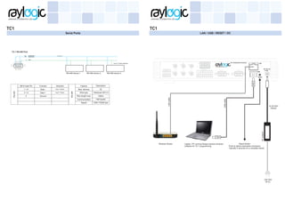
TC1
Automation Processor
Automation Processor suitable for interface and control of universal brands of following equipment types. ( Examples only...)
Technical Specifications
Processor:
Operating system:
Ethernet:
32 bit ARM core with dedicated ethernet core
RAY-OS
Real time pre emptive, multi threaded, multi tasking kernel
IR ports:
6 IR ports
Minimum drive of 2 IR emitters per port
1 built in IR blaster for line of site IR emission
10khz-1Mhz carrier capacity
I/O ports:
4 TTL I/O ports
0-12 VDC active low
Falling edge / Rising edge / active low event programmable
Debounced for noise surpression
Real time Clock:
Temperature compensated ( TCXO ) battery backed clock
Clock events configurable for daily / specific and seasonal
time scheduling
Status indicators: Front panel indicators for ethernet,serial,I/O,relays,IR ports
Operating conditions:
0-40 degrees centigrade ambient
0-95% relative humidity. Non condensing
Construction: Pearl white ABS enclosure
Dimensions:
Height: 52 mm
Width: 250 mm
Depth: 175 mm
Professional lighting dimming and control systems having infra-red remote controls or RS-232/RS-485 network based control
Non dimming and switching systems via suitable networkable relays on RS-485 serial ports
Motorised curtains,drapes,roller blinds,shears ,screens,lifts etc. via infra red or relay control
Weight: Gross weight TBD
Audio sources, selectors, pre amplifiers, mixers, receivers, media players etc. having an infra red remote control or serial port
Video equipment such as all types of televisions,projectors,DVD and blue ray players,media players via infra read and serial ports.
Composite video,S-video,HDMI,VGA switchers,scalers and routers via ir remote control and Rs232 serial ports.
Third party systems such as fire alarms,burglar alarms,acess control systems,IP camera,PTZ cameras,gas detectors etc.
10/100BaseT,auto negotiating,full/half duples,static IP or DHCP,
auto MDI-MDIX,TCP/IP,UDP
Specifications subject to change
TC-1
Electrical Diagram Mounting Dimensions
DC supply
RS-232 / 422 / 485
Ports
Relay Ports:
4 Low voltage relay ports
24 vdc 1A
MOV protected relays
Serial ports:
2 serial ports each configurable for following protocols:-
RS-232
RS-422
RS-485
System Bus: Raynet 2.0
IR capture:
Built in Infra Red capture for learning new remote control
commands in conjunction with Design Express software
Waveform display with editing for high accuracy capture
Boot time: Complete reboot in 5 seconds
Power supply: External 15-24 VDC 0.75A (max)
Serial ports
RS-232 / 422 / 485
Relay 1
Relay 2
Relay 3
Relay 4
I/O 1
I/O 2
I/O 3
I/O 4
I/O 0
I/R 1
I/R 2
I/R 3
I/R 4
I/R 5
I/R 6
I/R 7
Ethernet
USB
IR Capture
System Bus
250mm
175mm52mm
Network diagram
TC1
Device Layout
TC1
Systembus
IR(Infrared)ports
I/O
(Input/Outputports)
Relayports
Lowvoltage
Serialport1
RS232/422/485
Serialport2
RS232/422/485
EthernetLANport
USBport
Resetswitch
DCsupply
socket
IRblaster1
+5v
+3.3v
SYSRX
SYSTX
USBRX
USBTX
IRcapture
Serial1RX
Serial1TX
Serial2RX
Serial2TX
IO1
IO2
IO3
IO4
Relay1
Relay2
Relay3
Relay4
IR1
IR2
IR3
IR4
IR5
IR6
IR7(Blaster)
IRblaster2
IRblaster3
TC-1 front panel LED indicators / IR capture / IR blaster
TC-1 back panel connectors and terminations
iPAD
DHCP
192.168.1.201
Connected via wifi
Laptop
Running Design express software
DHCP
192.168.1.202
Connected via wifi
PC
Running Design express software
DHCP
192.168.1.203
Connected via wired LAN
Wireless Router
IP Address 192.168.1.1
DHCP starts at 192.168.1.200
Internet
TC-1
Manual IP
192.168.1.61
Connected via wired LAN
iPAD should be able to ping Laptop ,PC ,TC-1
Laptop should be able to ping iPAD ,PC ,TC-1
PC should be able to ping iPAD,Laptop, TC-1
IR Ports
TC1
System Bus
TC1
Data+
Data-
0
+15-24VDC0.25A
Data+
Data-
0
+15-24VDC
Systembus
TC-1 System bus wiring CAT 5 / 6
Raylogic wired TouchPanel
Data+
Data-
0
+15-24VDC
Raylogic GSM interface
IR ports 1 - 6
IR emitter with
indicator LED
Stereo3.5mmplug
Mono3.5mmplug
IR emitter fitted on device IR sensor
with 3M double sided tape
Tip
Sleeve
Sleeve -
Tip +
Tip
Ring
Sleeve
Sleeve & Ring -
Tip +
+
+
+
+
Ports can be extended to run up to 150-200 feet using a single CAT-5 pair.
An IR amplifier and / or thicker wiring may be required for greater lengths
or in case of improper triggering.
Shorted in wiring
Each IR port can drive 2 emitters each connected to a different type of equipment
Mono 6.3mm plug wiring and extension.
Stereo 6.3mm plug wiring and extension.
IO Ports
TC1
IR Capture
TC1
IRblasterPort7
IRcapture
IR1
IR2
IR3
IR4
IR5
IR6
IR7(Blaster)
IRblasterPort7
IRblasterPort7
< 1 inch (25mm)
2 inches (50mm)
approx. distance 2 inches (50mm)
LED indicators for IR ports
Contact open
Contact closed
Falling edge
event single shot
Rising edge
event single shot
Active low
event repetitive
Switch pressed Switch released
Switch held pressed
Each IO port when used as an input can have 3 different events defined with different actions programmable for each event.
Relay actuator of third party system.
Example: Motion sensors,security, fire alarm,
access control etc.
Push button switches / contact closures
/ potential free keypad switches
0 = Ground = Common
1 / 2 / 3 / 4 = IO used as INPUTs
Pole & N/O
contacts
IO ports used as INPUTS
IO Outputs driving external relays
0 = Ground = Common
1 / 2 / 3 / 4 = IO used as OUTPUTs
Outputs are active low PULL down
High Voltage
switching relays
IO ports used as OUTPUTS
DC
Power
Supply
N LNUP DN
+
-
230 VACCurtain motor
IO Outputs driving
active low contactsIO 1 / 2 / 3 / 4
0
250mA sink, 5-24VDC
IO ports may be used as single outputs or dual grouped outputs. Grouped outputs have built in interlock and mutually
exclusive operation. IO outputs can be programmed as permanent on / off and on for preset durations. ( On is an active low state )
Remote control position for IR capture
Place a book under the remote control to align the remote control emitter in height with the center of the TC-1
Front panel IR capture sensor location
Serial Ports
TC1
Relay ports
TC1
Relay ports driving external relays
Low voltage relay ports.
Max. 24 VDC 2A
High Voltage
switching relays
DC
Power
Supply
N LNUP DN
+
-
230 VACCurtain / Screen motors
Relay ports may be used as single relays or dual grouped relays. Grouped relays have built in interlock and mutually
exclusive operation. Relays can be programmed as permanent on / off and on for preset durations.
Motorised curtains low voltage
contact closure points
Potential free Input trigger contacts of
security systems,fire alarms, access
control systems etc.
Low voltage relay ports.
driving solid state relays.
DC
Power
Supply
N L
+
-
230 VAC
AC230VAC
DC3-12v
Solid state relay
+
-
Load
Serial Ports with RS-232 / RS-422 / RS-485 options
TC-1 RS-232 Port
1 2 3 4 5
6 7 8 9
RX
TX
GND
2
3
5
Slave RS-232 device
TC-1 RS-422 Port
1 2 3 4 5
6 7 8 9
RS 422 Receive Data -
GND
1
6
5
RS-422 device 1
RS 422 Receive Data +
4
9
RS 422 Transmit Data +
RS-422 Transmit Data -
RS-422 device 2 RS-422 device 3
up to 10 slave devices
Twisted pair
Twisted pair
RX+
RX-
TX-
TX+
0
TX+
RX+
RX-
TX-
TX+
0
TX+
RX+
RX-
TX-
TX+
0
TX+
DB-9 male Pin Function Direction
2 RXD Input
3 TXD Output
5 Ground
7 RTS Output
8 CTS Input
RS-232
Feature Description
Max. devices 2
Wire type 3/4 core shielded
Wire length max. 12m - 15m
Communication Full duplex
RS-232
Speed 1200-115200 bps
DB-9 male Pin Function Direction
1 RXD - Input
6 RXD +
Output
5 Ground
4 TXD+
Output9
RS-422
Feature Description
Max. devices 10
Wire type Twisted pair CAT 5 / 6
Wire length max. 1000m
Communication Full duplex
RS-422
Speed 1200-115200 bps
Input
TXD-
The serial ports are configured for type / baud rate / stop bits in the serial library of the DESIGN EXPRESS software for windows.
TC1
LAN / USB / RESET / DC
TC1
230 VAC
50 hz.
15-18 VDC
750mA
DCadaptor
Laptop / PC running Design express windows
software for TC-1 programming.
USBcable
LANcable
Reset Switch
Push to reboot automation processor.
Typically 5 seconds for a complete reboot.
Wireless Router
TC-1 RS-485 Port
1 2 3 4 5
6 7 8 9
GND5
RS-485 device 1
4+6
1+9
RS-485 Data +
RS-485 Data-
RS-485 device 2 RS-485 device 3
up to 31 slave devices
Twisted pair
DB-9 male Pin Function Direction
1 + 9 Data - Input / Output
4 + 6 Data +
5 Ground
RS-485
Feature Description
Max. devices 32
Wire type Twisted pair CAT 5 / 6
Wire length max. 1000m
Communication Half duplex
RS-485
Speed 1200-115200 bps
Input / Output
Serial Ports
TC1TC1
FAQ

TC-1_2015

  • 1.
    TC1 Automation Processor Automation Processorsuitable for interface and control of universal brands of following equipment types. ( Examples only...) Technical Specifications Processor: Operating system: Ethernet: 32 bit ARM core with dedicated ethernet core RAY-OS Real time pre emptive, multi threaded, multi tasking kernel IR ports: 6 IR ports Minimum drive of 2 IR emitters per port 1 built in IR blaster for line of site IR emission 10khz-1Mhz carrier capacity I/O ports: 4 TTL I/O ports 0-12 VDC active low Falling edge / Rising edge / active low event programmable Debounced for noise surpression Real time Clock: Temperature compensated ( TCXO ) battery backed clock Clock events configurable for daily / specific and seasonal time scheduling Status indicators: Front panel indicators for ethernet,serial,I/O,relays,IR ports Operating conditions: 0-40 degrees centigrade ambient 0-95% relative humidity. Non condensing Construction: Pearl white ABS enclosure Dimensions: Height: 52 mm Width: 250 mm Depth: 175 mm Professional lighting dimming and control systems having infra-red remote controls or RS-232/RS-485 network based control Non dimming and switching systems via suitable networkable relays on RS-485 serial ports Motorised curtains,drapes,roller blinds,shears ,screens,lifts etc. via infra red or relay control Weight: Gross weight TBD Audio sources, selectors, pre amplifiers, mixers, receivers, media players etc. having an infra red remote control or serial port Video equipment such as all types of televisions,projectors,DVD and blue ray players,media players via infra read and serial ports. Composite video,S-video,HDMI,VGA switchers,scalers and routers via ir remote control and Rs232 serial ports. Third party systems such as fire alarms,burglar alarms,acess control systems,IP camera,PTZ cameras,gas detectors etc. 10/100BaseT,auto negotiating,full/half duples,static IP or DHCP, auto MDI-MDIX,TCP/IP,UDP Specifications subject to change TC-1 Electrical Diagram Mounting Dimensions DC supply RS-232 / 422 / 485 Ports Relay Ports: 4 Low voltage relay ports 24 vdc 1A MOV protected relays Serial ports: 2 serial ports each configurable for following protocols:- RS-232 RS-422 RS-485 System Bus: Raynet 2.0 IR capture: Built in Infra Red capture for learning new remote control commands in conjunction with Design Express software Waveform display with editing for high accuracy capture Boot time: Complete reboot in 5 seconds Power supply: External 15-24 VDC 0.75A (max) Serial ports RS-232 / 422 / 485 Relay 1 Relay 2 Relay 3 Relay 4 I/O 1 I/O 2 I/O 3 I/O 4 I/O 0 I/R 1 I/R 2 I/R 3 I/R 4 I/R 5 I/R 6 I/R 7 Ethernet USB IR Capture System Bus 250mm 175mm52mm
  • 2.
    Network diagram TC1 Device Layout TC1 Systembus IR(Infrared)ports I/O (Input/Outputports) Relayports Lowvoltage Serialport1 RS232/422/485 Serialport2 RS232/422/485 EthernetLANport USBport Resetswitch DCsupply socket IRblaster1 +5v +3.3v SYSRX SYSTX USBRX USBTX IRcapture Serial1RX Serial1TX Serial2RX Serial2TX IO1 IO2 IO3 IO4 Relay1 Relay2 Relay3 Relay4 IR1 IR2 IR3 IR4 IR5 IR6 IR7(Blaster) IRblaster2 IRblaster3 TC-1front panel LED indicators / IR capture / IR blaster TC-1 back panel connectors and terminations iPAD DHCP 192.168.1.201 Connected via wifi Laptop Running Design express software DHCP 192.168.1.202 Connected via wifi PC Running Design express software DHCP 192.168.1.203 Connected via wired LAN Wireless Router IP Address 192.168.1.1 DHCP starts at 192.168.1.200 Internet TC-1 Manual IP 192.168.1.61 Connected via wired LAN iPAD should be able to ping Laptop ,PC ,TC-1 Laptop should be able to ping iPAD ,PC ,TC-1 PC should be able to ping iPAD,Laptop, TC-1
  • 3.
    IR Ports TC1 System Bus TC1 Data+ Data- 0 +15-24VDC0.25A Data+ Data- 0 +15-24VDC Systembus TC-1System bus wiring CAT 5 / 6 Raylogic wired TouchPanel Data+ Data- 0 +15-24VDC Raylogic GSM interface IR ports 1 - 6 IR emitter with indicator LED Stereo3.5mmplug Mono3.5mmplug IR emitter fitted on device IR sensor with 3M double sided tape Tip Sleeve Sleeve - Tip + Tip Ring Sleeve Sleeve & Ring - Tip + + + + + Ports can be extended to run up to 150-200 feet using a single CAT-5 pair. An IR amplifier and / or thicker wiring may be required for greater lengths or in case of improper triggering. Shorted in wiring Each IR port can drive 2 emitters each connected to a different type of equipment Mono 6.3mm plug wiring and extension. Stereo 6.3mm plug wiring and extension.
  • 4.
    IO Ports TC1 IR Capture TC1 IRblasterPort7 IRcapture IR1 IR2 IR3 IR4 IR5 IR6 IR7(Blaster) IRblasterPort7 IRblasterPort7 <1 inch (25mm) 2 inches (50mm) approx. distance 2 inches (50mm) LED indicators for IR ports Contact open Contact closed Falling edge event single shot Rising edge event single shot Active low event repetitive Switch pressed Switch released Switch held pressed Each IO port when used as an input can have 3 different events defined with different actions programmable for each event. Relay actuator of third party system. Example: Motion sensors,security, fire alarm, access control etc. Push button switches / contact closures / potential free keypad switches 0 = Ground = Common 1 / 2 / 3 / 4 = IO used as INPUTs Pole & N/O contacts IO ports used as INPUTS IO Outputs driving external relays 0 = Ground = Common 1 / 2 / 3 / 4 = IO used as OUTPUTs Outputs are active low PULL down High Voltage switching relays IO ports used as OUTPUTS DC Power Supply N LNUP DN + - 230 VACCurtain motor IO Outputs driving active low contactsIO 1 / 2 / 3 / 4 0 250mA sink, 5-24VDC IO ports may be used as single outputs or dual grouped outputs. Grouped outputs have built in interlock and mutually exclusive operation. IO outputs can be programmed as permanent on / off and on for preset durations. ( On is an active low state ) Remote control position for IR capture Place a book under the remote control to align the remote control emitter in height with the center of the TC-1 Front panel IR capture sensor location
  • 5.
    Serial Ports TC1 Relay ports TC1 Relayports driving external relays Low voltage relay ports. Max. 24 VDC 2A High Voltage switching relays DC Power Supply N LNUP DN + - 230 VACCurtain / Screen motors Relay ports may be used as single relays or dual grouped relays. Grouped relays have built in interlock and mutually exclusive operation. Relays can be programmed as permanent on / off and on for preset durations. Motorised curtains low voltage contact closure points Potential free Input trigger contacts of security systems,fire alarms, access control systems etc. Low voltage relay ports. driving solid state relays. DC Power Supply N L + - 230 VAC AC230VAC DC3-12v Solid state relay + - Load Serial Ports with RS-232 / RS-422 / RS-485 options TC-1 RS-232 Port 1 2 3 4 5 6 7 8 9 RX TX GND 2 3 5 Slave RS-232 device TC-1 RS-422 Port 1 2 3 4 5 6 7 8 9 RS 422 Receive Data - GND 1 6 5 RS-422 device 1 RS 422 Receive Data + 4 9 RS 422 Transmit Data + RS-422 Transmit Data - RS-422 device 2 RS-422 device 3 up to 10 slave devices Twisted pair Twisted pair RX+ RX- TX- TX+ 0 TX+ RX+ RX- TX- TX+ 0 TX+ RX+ RX- TX- TX+ 0 TX+ DB-9 male Pin Function Direction 2 RXD Input 3 TXD Output 5 Ground 7 RTS Output 8 CTS Input RS-232 Feature Description Max. devices 2 Wire type 3/4 core shielded Wire length max. 12m - 15m Communication Full duplex RS-232 Speed 1200-115200 bps DB-9 male Pin Function Direction 1 RXD - Input 6 RXD + Output 5 Ground 4 TXD+ Output9 RS-422 Feature Description Max. devices 10 Wire type Twisted pair CAT 5 / 6 Wire length max. 1000m Communication Full duplex RS-422 Speed 1200-115200 bps Input TXD- The serial ports are configured for type / baud rate / stop bits in the serial library of the DESIGN EXPRESS software for windows.
  • 6.
    TC1 LAN / USB/ RESET / DC TC1 230 VAC 50 hz. 15-18 VDC 750mA DCadaptor Laptop / PC running Design express windows software for TC-1 programming. USBcable LANcable Reset Switch Push to reboot automation processor. Typically 5 seconds for a complete reboot. Wireless Router TC-1 RS-485 Port 1 2 3 4 5 6 7 8 9 GND5 RS-485 device 1 4+6 1+9 RS-485 Data + RS-485 Data- RS-485 device 2 RS-485 device 3 up to 31 slave devices Twisted pair DB-9 male Pin Function Direction 1 + 9 Data - Input / Output 4 + 6 Data + 5 Ground RS-485 Feature Description Max. devices 32 Wire type Twisted pair CAT 5 / 6 Wire length max. 1000m Communication Half duplex RS-485 Speed 1200-115200 bps Input / Output Serial Ports
  • 7.