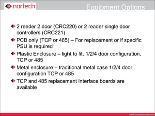
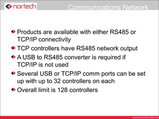
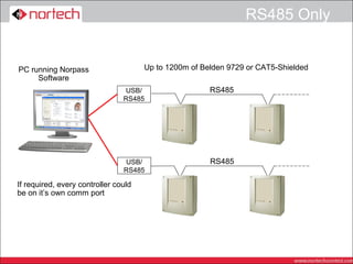
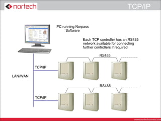
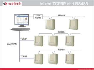
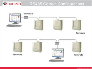
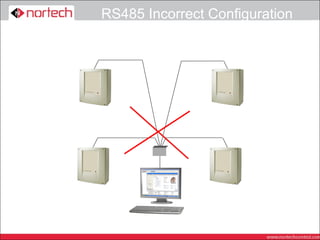
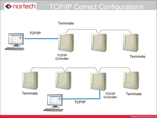
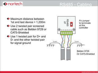
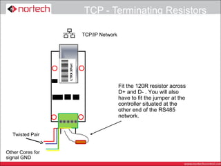
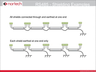
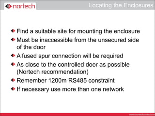
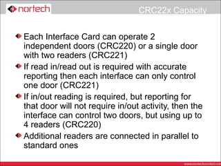
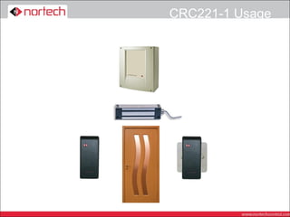
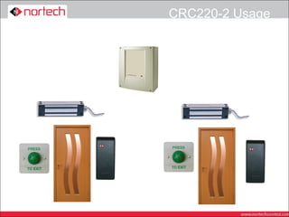
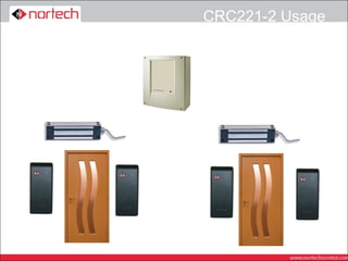
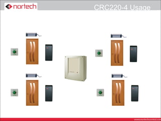
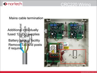
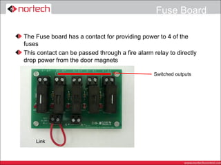
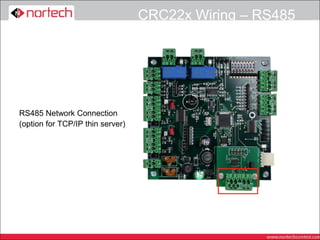
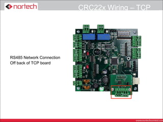
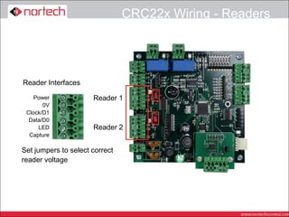
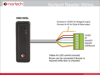
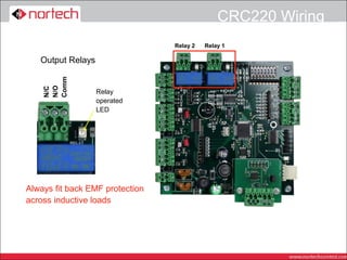
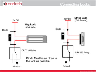
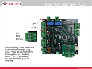
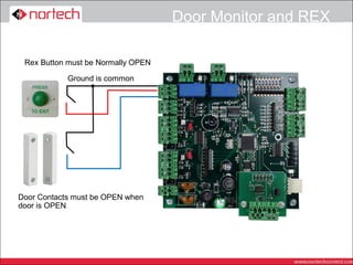
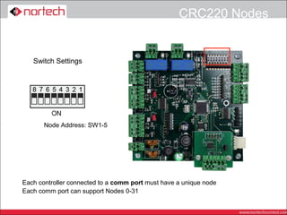
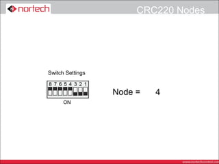
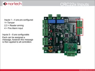
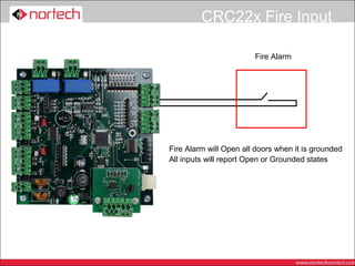
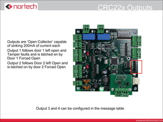
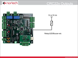
CRC220
   Network
Installation
Equipment Options

2 reader 2 door (CRC220) or 2 reader single door
controllers (CRC221)
PCB only (TCP or 485) – For replacement or if specific
PSU is required
Plastic Enclosure – light to fit, 1/2/4 door configuration,
TCP or 485
Metal enclosure – traditional metal case 1/2/4 door
configuration TCP or 485
TCP and 485 replacement Interface boards are
available
Communications Network


Products are available with either RS485 or
TCP/IP connectivity
TCP controllers have RS485 network output
A USB to RS485 converter is required if
TCP/IP is not used
Several USB or TCP/IP comm ports can be set
up with up to 32 controllers on each
Overall limit is 128 controllers
RS485 Only


PC running Norpass                    Up to 1200m of Belden 9729 or CAT5-Shielded
     Software
                                 USB/                  RS485
                                RS485


                                USB/                   RS485
                                RS485

If required, every controller could
be on it’s own comm port
TCP/IP

                   PC running Norpass
                        Software

                                 Each TCP controller has an RS485
                                 network available for connecting
                                 further controllers if required

                                          RS485


          TCP/IP

LAN/WAN

                                          RS485


          TCP/IP
Mixed TCP/IP and RS485

                   USB/        RS485
                   RS485


                               RS485


          TCP/IP

LAN/WAN

                               RS485


          TCP/IP
RS485 Correct Configurations

            Terminate


                                         Terminate


Terminate                              Terminate
RS485 Incorrect Configuration
TCP/IP Correct Configurations

               Terminate

    TCP/IP


               TCP/IP                              Terminate
              Controller


Terminate                            TCP/IP      Terminate
                                    Controller
                           TCP/IP
RS485 - Cabling


Maximum distance between
                                          Fit Jumper
1st and last device = 1,200m              to terminate
Use 2 twisted pair screened               at this
                                          controller
cable such as Belden 9729 or
CAT5-Shielded
Use 1 twisted pair for D+ and
D- and the other twisted pair
for signal ground

                                        Belden 9729
                                        Or CAT5-Shielded
TCP - Terminating Resistors

                               TCP/IP Network


                  LTRX XPort


                                                Fit the 120R resistor across
                                                D+ and D- . You will also
                                                have to fit the jumper at the
                                                controller situated at the
                                                other end of the RS485
                                                network.


  Twisted Pair


Other Cores for
signal GND
Checking the data cable


At one end of the cable, ensure the resistance
between the wires carrying D+ and D- is
between 60 – 80 ohms if there are any shorts,
check the cable, if the resistance is much
higher, check the terminating jumpers or
resistors are fitted.
Check there is no short between either data
core and the shield
Check the shield is continuous and connected
to earth at one end
RS485 - Shielding Examples

All shields connected through and earthed at one end


Each shield earthed at one end only
CRC220 Installation
Locating the Enclosures


Find a suitable site for mounting the enclosure
Must be inaccessible from the unsecured side
of the door
A fused spur connection will be required
As close to the controlled door as possible
(Nortech recommendation)
Remember 1200m RS485 constraint
If necessary use more than one network
CRC22x Capacity


Each Interface Card can operate 2
independent doors (CRC220) or a single door
with two readers (CRC221)
If read in/read out is required with accurate
reporting then each interface can only control
one door (CRC221)
If in/out reading is required, but reporting for
that door will not require in/out activity, then the
interface can control two doors, but using up to
4 readers (CRC220)
Additional readers are connected in parallel to
standard ones
CRC221-1 Usage
CRC220-2 Usage
CRC221-2 Usage
CRC220-4 Usage
CRC220 Wiring


 Mains cable termination


Additional individually
fused 12VDC supplies
Battery backup facility
Remove Tab and posts
if required
Fuse Board

The Fuse board has a contact for providing power to 4 of the
fuses
This contact can be passed through a fire alarm relay to directly
drop power from the door magnets

                                                Switched outputs


    Link
CRC22x Wiring – RS485


RS485 Network Connection
(option for TCP/IP thin server)
CRC22x Wiring – TCP


RS485 Network Connection
Off back of TCP board
CRC22x Wiring - Readers


Reader Interfaces

    Power             Reader 1
       0V
 Clock/D1
  Data/D0
     LED              Reader 2
  Capture

Set jumpers to select correct
reader voltage
Nortech Reader Wiring

EM2100SL
                  Connect to 12VDC for Wiegand output
                  Connect to 0V for Clock & Data output


                                                12VDC
                                                0V
                                                Clock/D1
                                                Data/D0
                                                LED/Buzzer


           Yellow for LED control (normal)
           Brown can be connected if Buzzer is
           required while door is unlocked.
Locks

Choice of lock will depend on the type of installation
Mag Lock are always Power to Lock (Fail Safe) so
require battery back up to maintain security in event of
a power fail
Mag locks are simple to add to an existing door
Electric strikes can be Power to Lock or Power to
Unlock (Fail Secure). Power to unlock (fail secure)
does not require battery back up to maintain security in
a power failure, but may need a mechanical override
for H&S reasons
Strike locks require more knowledge of Door furniture
and are more difficult to fit
Connecting Locks


As with all systems, back EMF devices MUST
be fitted correctly
We always recommend using a DIODE
MOV’s or capacitor/resistor networks can be
used for AC applications, however they are not
as effective as diodes and can fail in the field
with no indication. (This means protection will
stop)
As the output is a voltage free relay, it can be
used for Fail Safe or Fail Secure installations
CRC220 Wiring
                                 Relay 2   Relay 1

   Output Relays
    Comm
    N/O
    N/C


                   Relay
                   operated
                   LED


Always fit back EMF protection
across inductive loads
Connecting Locks


                                                    12V DC   Strike Lock
        12V DC                                               (Fail Secure)
                    Mag Lock
                     (Fail Safe)
Diode                                       Diode


                  CRC220 Relay
                                                             CRC220 Relay

                     Diode Must be as close to
                     the lock as possible
         Ground                                     Ground
Door Monitor and REX


                            Door 1
                            Door 2

            0V
            REX
            Contact


For monitoring Doors, we do not
recommend monitored Mag-
locks. These do not monitor the
door position, only the lock
status. This compromises
security and is not good for
reporting
Door Monitor and REX

 Rex Button must be Normally OPEN

            Ground is common


Door Contacts must be OPEN when
door is OPEN
CRC220 Nodes


   Switch Settings


       Node Address: SW1-5


Each controller connected to a comm port must have a unique node
Each comm port can support Nodes 0-31
CRC220 Nodes


Switch Settings


                  Node =   0
                           3
                           4
                           2
                           1
CRC22x Inputs


  Inputs 1 – 4 are pre configured
  1= Tamper
  2,3 = Reader arming
  4 = Fire Alarm input


Inputs 5 – 8 are configurable
Each can be assigned a
message, however this message
is then applied to all controllers
CRC22x Fire Input

                        Fire Alarm


Fire Alarm will Open all doors when it is grounded
All inputs will report Open or Grounded states
CRC22x Outputs


Outputs are ‘Open Collector’ capable
of sinking 200mA of current each
Output 1 follows door 1 left open and
Tamper faults and is latched on by
Door 1 Forced Open
Output 2 follows Door 2 left Open and
is latched on by door 2 Forced Open


                 Output 3 and 4 can be configured in the message table
CRC22x Outputs


    12 or 5V dc


Relay/LED/Buzzer etc
Nortech Door Controllers -   crc220 network installation

Nortech Door Controllers - crc220 network installation

  • 1.
    CRC220 Network Installation
  • 2.
    Equipment Options 2 reader2 door (CRC220) or 2 reader single door controllers (CRC221) PCB only (TCP or 485) – For replacement or if specific PSU is required Plastic Enclosure – light to fit, 1/2/4 door configuration, TCP or 485 Metal enclosure – traditional metal case 1/2/4 door configuration TCP or 485 TCP and 485 replacement Interface boards are available
  • 3.
    Communications Network Products areavailable with either RS485 or TCP/IP connectivity TCP controllers have RS485 network output A USB to RS485 converter is required if TCP/IP is not used Several USB or TCP/IP comm ports can be set up with up to 32 controllers on each Overall limit is 128 controllers
  • 4.
    RS485 Only PC runningNorpass Up to 1200m of Belden 9729 or CAT5-Shielded Software USB/ RS485 RS485 USB/ RS485 RS485 If required, every controller could be on it’s own comm port
  • 5.
    TCP/IP PC running Norpass Software Each TCP controller has an RS485 network available for connecting further controllers if required RS485 TCP/IP LAN/WAN RS485 TCP/IP
  • 6.
    Mixed TCP/IP andRS485 USB/ RS485 RS485 RS485 TCP/IP LAN/WAN RS485 TCP/IP
  • 7.
    RS485 Correct Configurations Terminate Terminate Terminate Terminate
  • 8.
  • 9.
    TCP/IP Correct Configurations Terminate TCP/IP TCP/IP Terminate Controller Terminate TCP/IP Terminate Controller TCP/IP
  • 10.
    RS485 - Cabling Maximumdistance between Fit Jumper 1st and last device = 1,200m to terminate Use 2 twisted pair screened at this controller cable such as Belden 9729 or CAT5-Shielded Use 1 twisted pair for D+ and D- and the other twisted pair for signal ground Belden 9729 Or CAT5-Shielded
  • 11.
    TCP - TerminatingResistors TCP/IP Network LTRX XPort Fit the 120R resistor across D+ and D- . You will also have to fit the jumper at the controller situated at the other end of the RS485 network. Twisted Pair Other Cores for signal GND
  • 12.
    Checking the datacable At one end of the cable, ensure the resistance between the wires carrying D+ and D- is between 60 – 80 ohms if there are any shorts, check the cable, if the resistance is much higher, check the terminating jumpers or resistors are fitted. Check there is no short between either data core and the shield Check the shield is continuous and connected to earth at one end
  • 13.
    RS485 - ShieldingExamples All shields connected through and earthed at one end Each shield earthed at one end only
  • 14.
  • 15.
    Locating the Enclosures Finda suitable site for mounting the enclosure Must be inaccessible from the unsecured side of the door A fused spur connection will be required As close to the controlled door as possible (Nortech recommendation) Remember 1200m RS485 constraint If necessary use more than one network
  • 16.
    CRC22x Capacity Each InterfaceCard can operate 2 independent doors (CRC220) or a single door with two readers (CRC221) If read in/read out is required with accurate reporting then each interface can only control one door (CRC221) If in/out reading is required, but reporting for that door will not require in/out activity, then the interface can control two doors, but using up to 4 readers (CRC220) Additional readers are connected in parallel to standard ones
  • 17.
  • 18.
  • 19.
  • 20.
  • 21.
    CRC220 Wiring Mainscable termination Additional individually fused 12VDC supplies Battery backup facility Remove Tab and posts if required
  • 22.
    Fuse Board The Fuseboard has a contact for providing power to 4 of the fuses This contact can be passed through a fire alarm relay to directly drop power from the door magnets Switched outputs Link
  • 23.
    CRC22x Wiring –RS485 RS485 Network Connection (option for TCP/IP thin server)
  • 24.
    CRC22x Wiring –TCP RS485 Network Connection Off back of TCP board
  • 25.
    CRC22x Wiring -Readers Reader Interfaces Power Reader 1 0V Clock/D1 Data/D0 LED Reader 2 Capture Set jumpers to select correct reader voltage
  • 26.
    Nortech Reader Wiring EM2100SL Connect to 12VDC for Wiegand output Connect to 0V for Clock & Data output 12VDC 0V Clock/D1 Data/D0 LED/Buzzer Yellow for LED control (normal) Brown can be connected if Buzzer is required while door is unlocked.
  • 27.
    Locks Choice of lockwill depend on the type of installation Mag Lock are always Power to Lock (Fail Safe) so require battery back up to maintain security in event of a power fail Mag locks are simple to add to an existing door Electric strikes can be Power to Lock or Power to Unlock (Fail Secure). Power to unlock (fail secure) does not require battery back up to maintain security in a power failure, but may need a mechanical override for H&S reasons Strike locks require more knowledge of Door furniture and are more difficult to fit
  • 28.
    Connecting Locks As withall systems, back EMF devices MUST be fitted correctly We always recommend using a DIODE MOV’s or capacitor/resistor networks can be used for AC applications, however they are not as effective as diodes and can fail in the field with no indication. (This means protection will stop) As the output is a voltage free relay, it can be used for Fail Safe or Fail Secure installations
  • 29.
    CRC220 Wiring Relay 2 Relay 1 Output Relays Comm N/O N/C Relay operated LED Always fit back EMF protection across inductive loads
  • 30.
    Connecting Locks 12V DC Strike Lock 12V DC (Fail Secure) Mag Lock (Fail Safe) Diode Diode CRC220 Relay CRC220 Relay Diode Must be as close to the lock as possible Ground Ground
  • 31.
    Door Monitor andREX Door 1 Door 2 0V REX Contact For monitoring Doors, we do not recommend monitored Mag- locks. These do not monitor the door position, only the lock status. This compromises security and is not good for reporting
  • 32.
    Door Monitor andREX Rex Button must be Normally OPEN Ground is common Door Contacts must be OPEN when door is OPEN
  • 33.
    CRC220 Nodes Switch Settings Node Address: SW1-5 Each controller connected to a comm port must have a unique node Each comm port can support Nodes 0-31
  • 34.
  • 35.
    CRC22x Inputs Inputs 1 – 4 are pre configured 1= Tamper 2,3 = Reader arming 4 = Fire Alarm input Inputs 5 – 8 are configurable Each can be assigned a message, however this message is then applied to all controllers
  • 36.
    CRC22x Fire Input Fire Alarm Fire Alarm will Open all doors when it is grounded All inputs will report Open or Grounded states
  • 37.
    CRC22x Outputs Outputs are‘Open Collector’ capable of sinking 200mA of current each Output 1 follows door 1 left open and Tamper faults and is latched on by Door 1 Forced Open Output 2 follows Door 2 left Open and is latched on by door 2 Forced Open Output 3 and 4 can be configured in the message table
  • 38.
    CRC22x Outputs 12 or 5V dc Relay/LED/Buzzer etc