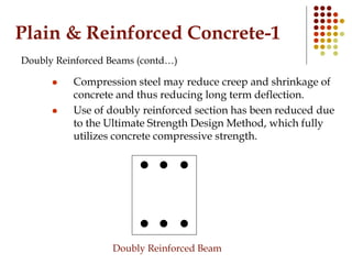
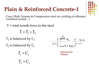
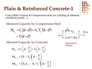
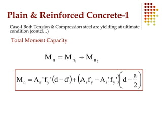
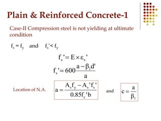
Plain & Reinforced
Concrete-1
CE3601
Lecture # 17
3rd April 2012
Flexural Analysis and
Design of Beams
(Ultimate Strength Design of Beams)
Plain & Reinforced Concrete-1
Doubly Reinforced Beams
“Beams having both tension and compression reinforcement
to allow the depth of beam to be lesser than minimum depth
for singly reinforced beam”
 By using lesser depth the lever arm reduces and to develop
the same force more area of steel is required, so solution is
costly.
 Ductility will be increased by providing compression steel.
 Hanger bars can also be used as compression steel reducing
the cost up to certain cost.
 For high rise buildings the extra cost of the shallow deep
beams is offset by saving due to less story height.
Plain & Reinforced Concrete-1
Doubly Reinforced Beams (contd…)
 Compression steel may reduce creep and shrinkage of
concrete and thus reducing long term deflection.
 Use of doubly reinforced section has been reduced due
to the Ultimate Strength Design Method, which fully
utilizes concrete compressive strength.
Doubly Reinforced Beam
Plain & Reinforced Concrete-1
Behavior Doubly Reinforced Beams
Tension steel always yields in D.R.B.
There are two possible cases:
1. Case-I Compression steel is yielding at
ultimate condition.
2. Case-II Compression steel is NOT yielding
at ultimate condition.
Plain & Reinforced Concrete-1
Behavior Doubly Reinforced Beams
Cc
T = Asfs
N.A.
εcu= 0.003
Strain Diagram Internal Force
Diagram
εs
h
c
d
b 0.85fc
a
Whitney’s
Stress Diagram
(d-d’)
fs
d
εs’ fs’
Cs
d – a/2
T = Asfs
Cs=As’fs’
Cc=0.85fc’ba
fs=Esεs
fs’=Esεs’
Plain & Reinforced Concrete-1
Behavior Doubly Reinforced Beams (contd…)
Case-I Both Tension & Compression steel are yielding at
ultimate condition
fs = fy and fs’=fy
Location of N.A.
Consider equilibrium of forces in longitudinal direction
sc CCT 
yscys f'Aba'f85.0fA 
 
b'f85.0
f'AA
a
c
yss 

1β
a
c and
Plain & Reinforced Concrete-1
Case-I Both Tension & Compression steel are yielding at ultimate
condition (contd…)
c
d'c
0.003
'εs 

εcu= 0.003
Strain Diagram
εs
c εs’
d’
B
D
E
C
A
Δ ABC & ADE





 

c
d'c
0.003'εs
1
1
s
β
β
c
d'c
0.003'ε 




 






 

a
d'βa
0.003'ε 1
s
If εs’ ≥ εy compression steel is yielding.
If εs’ < εy compression steel is NOT yielding.
(1)
Plain & Reinforced Concrete-1
Case-I Both Tension & Compression steel are yielding at ultimate
condition (contd…)
Cc
T = Asfy
N.A.
Internal Force
Diagram
(d-d’)
Cs
d – a/2
T = total tensile force in the steel
21 TTT 
T1 is balanced by Cs
T2 is balanced by Cc
s1 CT 
c2 CT 
Plain & Reinforced Concrete-1
Case-I Both Tension & Compression steel are yielding at ultimate
condition (contd…)
Cc
T = Asfy
N.A.
Internal Force
Diagram
(d-d’)
Cs
d – a/2
Moment Capacity by Compression Steel
   'dd'f'A'ddCM yssn1

 'ddT1 
Moment Capacity by Concrete













2
a
dT
2
a
dCM 2cn2
  






2
a
dTTM 1n 2
  






2
a
d'f'AfAM ysysn 2
Plain & Reinforced Concrete-1
Case-I Both Tension & Compression steel are yielding at ultimate
condition (contd…)
Total Moment Capacity
21 nnn MMM 
    






2
a
d'f'AfA'dd'f'AM ysysysn
Plain & Reinforced Concrete-1
Case-II Compression steel is not yielding at ultimate
condition
fs = fy and fs’< fy
'εE'f ss 
b'f85.0
'f'AfA
a
c
ssys 

1β
a
c and
a
d'βa
600'f 1
s


Location of N.A.
Concluded

Lec 17

  • 1.
    Plain & Reinforced Concrete-1 CE3601 Lecture# 17 3rd April 2012 Flexural Analysis and Design of Beams (Ultimate Strength Design of Beams)
  • 2.
    Plain & ReinforcedConcrete-1 Doubly Reinforced Beams “Beams having both tension and compression reinforcement to allow the depth of beam to be lesser than minimum depth for singly reinforced beam”  By using lesser depth the lever arm reduces and to develop the same force more area of steel is required, so solution is costly.  Ductility will be increased by providing compression steel.  Hanger bars can also be used as compression steel reducing the cost up to certain cost.  For high rise buildings the extra cost of the shallow deep beams is offset by saving due to less story height.
  • 3.
    Plain & ReinforcedConcrete-1 Doubly Reinforced Beams (contd…)  Compression steel may reduce creep and shrinkage of concrete and thus reducing long term deflection.  Use of doubly reinforced section has been reduced due to the Ultimate Strength Design Method, which fully utilizes concrete compressive strength. Doubly Reinforced Beam
  • 4.
    Plain & ReinforcedConcrete-1 Behavior Doubly Reinforced Beams Tension steel always yields in D.R.B. There are two possible cases: 1. Case-I Compression steel is yielding at ultimate condition. 2. Case-II Compression steel is NOT yielding at ultimate condition.
  • 5.
    Plain & ReinforcedConcrete-1 Behavior Doubly Reinforced Beams Cc T = Asfs N.A. εcu= 0.003 Strain Diagram Internal Force Diagram εs h c d b 0.85fc a Whitney’s Stress Diagram (d-d’) fs d εs’ fs’ Cs d – a/2 T = Asfs Cs=As’fs’ Cc=0.85fc’ba fs=Esεs fs’=Esεs’
  • 6.
    Plain & ReinforcedConcrete-1 Behavior Doubly Reinforced Beams (contd…) Case-I Both Tension & Compression steel are yielding at ultimate condition fs = fy and fs’=fy Location of N.A. Consider equilibrium of forces in longitudinal direction sc CCT  yscys f'Aba'f85.0fA    b'f85.0 f'AA a c yss   1β a c and
  • 7.
    Plain & ReinforcedConcrete-1 Case-I Both Tension & Compression steel are yielding at ultimate condition (contd…) c d'c 0.003 'εs   εcu= 0.003 Strain Diagram εs c εs’ d’ B D E C A Δ ABC & ADE         c d'c 0.003'εs 1 1 s β β c d'c 0.003'ε                 a d'βa 0.003'ε 1 s If εs’ ≥ εy compression steel is yielding. If εs’ < εy compression steel is NOT yielding. (1)
  • 8.
    Plain & ReinforcedConcrete-1 Case-I Both Tension & Compression steel are yielding at ultimate condition (contd…) Cc T = Asfy N.A. Internal Force Diagram (d-d’) Cs d – a/2 T = total tensile force in the steel 21 TTT  T1 is balanced by Cs T2 is balanced by Cc s1 CT  c2 CT 
  • 9.
    Plain & ReinforcedConcrete-1 Case-I Both Tension & Compression steel are yielding at ultimate condition (contd…) Cc T = Asfy N.A. Internal Force Diagram (d-d’) Cs d – a/2 Moment Capacity by Compression Steel    'dd'f'A'ddCM yssn1   'ddT1  Moment Capacity by Concrete              2 a dT 2 a dCM 2cn2          2 a dTTM 1n 2          2 a d'f'AfAM ysysn 2
  • 10.
    Plain & ReinforcedConcrete-1 Case-I Both Tension & Compression steel are yielding at ultimate condition (contd…) Total Moment Capacity 21 nnn MMM             2 a d'f'AfA'dd'f'AM ysysysn
  • 11.
    Plain & ReinforcedConcrete-1 Case-II Compression steel is not yielding at ultimate condition fs = fy and fs’< fy 'εE'f ss  b'f85.0 'f'AfA a c ssys   1β a c and a d'βa 600'f 1 s   Location of N.A.
  • 12.