Introduction to theSystems Approach
UNIT-1
• SYSTEM ARCHITECTURE: AN OVERVIEW
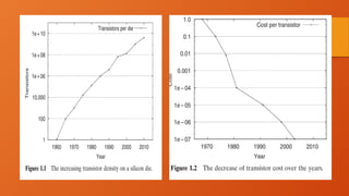
1. The past 40 years have seen amazing advances in silicon technology and resulting increases in
transistor density and performance.
2. In 1966, Fairchild Semiconductor [84] introduced a quad two input NAND gate with about 10
transistors on a die. In 2008, the Intel quad - core Itanium processor has 2 billion transistors
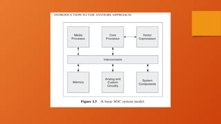
3. A system - on - chip (SOC) architecture is an ensemble of processors, memories, and
interconnects tailored to an application domain
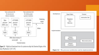
4. A simple example of such an architecture is the Emotion Engine for the Sony PlayStation , which
has two main functions: behavior simulation and geometry translation. This system contains three
essential components: a main processor of the reduced instruction set computer (RISC) style
[118] and two vector processing units, VPU0 and VPU1, each of which contains four parallel
processors of the single instruction, multiple data (SIMD) stream style
4.
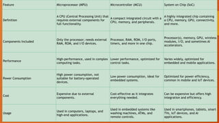
Feature Microprocessor (MPU)Microcontroller (MCU) System on Chip (SoC)
Definition
A CPU (Central Processing Unit) that
requires external components for
full functionality.
A compact integrated circuit with a
CPU, memory, and peripherals.
A highly integrated chip containing
a CPU, memory, GPU, connectivity,
and more.
Components Included
Only the processor; needs external
RAM, ROM, and I/O devices.
Processor, RAM, ROM, I/O ports,
timers, and more in one chip.
Processor(s), memory, GPU, wireless
modules, I/O, and sometimes AI
accelerators.
Performance
High-performance, used in complex
computing tasks.
Lower performance, optimized for
control tasks.
Varies widely, optimized for
embedded and mobile applications.
Power Consumption
High power consumption, not
suitable for battery-operated
devices.
Low power consumption, ideal for
embedded systems.
Optimized for power efficiency,
common in mobile and IoT devices.
Cost
Expensive due to external
components.
Cost-effective as it integrates
everything needed.
Can be expensive but offers high
integration and efficiency.
Usage
Used in computers, laptops, and
high-end applications.
Used in embedded systems like
washing machines, ATMs, and
remote controls.
Used in smartphones, tablets, smart
TVs, IoT devices, and AI
applications.
5.
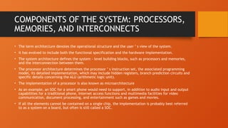
COMPONENTS OF THESYSTEM: PROCESSORS,
MEMORIES, AND INTERCONNECTS
• The term architecture denotes the operational structure and the user ’ s view of the system.
• it has evolved to include both the functional specification and the hardware implementation.
• The system architecture defines the system - level building blocks, such as processors and memories,
and the interconnection between them.
• The processor architecture determines the processor ’ s instruction set, the associated programming
model, its detailed implementation, which may include hidden registers, branch prediction circuits and
specific details concerning the ALU (arithmetic logic unit).
• The implementation of a processor is also known as microarchitecture
• As an example, an SOC for a smart phone would need to support, in addition to audio input and output
capabilities for a traditional phone, Internet access functions and multimedia facilities for video
communication, document processing, and entertainment such as games and movies.
• If all the elements cannot be contained on a single chip, the implementation is probably best referred
to as a system on a board, but often is still called a SOC.
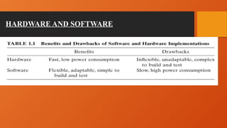
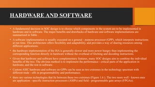
HARDWARE AND SOFTWARE
•A fundamental decision in SOC design is to choose which components in the system are to be implemented in
hardware and in software. The major benefits and drawbacks of hardware and software implementations are
summarized in Table .
• A software implementation is usually executed on a general - purpose processor (GPP), which interprets instructions
at run time. This architecture offers flexibility and adaptability, and provides a way of sharing resources among
different applications;
• the hardware implementation of the ISA is generally slower and more power hungry than implementing the
corresponding function directly in hardware without the overhead of fetching and decoding instructions.
• Given that hardware and software have complementary features, many SOC designs aim to combine the individual
benefits of the two. The obvious method is to implement the performance - critical parts of the application in
hardware, and the rest in software.
• Custom ASIC hardware and software on GPPs can be seen as two extremes in the technology spectrum with
different trade - offs in programmability and performance;
• there are various technologies that lie between these two extremes (Figure 1.6 ). The two more well - known ones
are application - specific instruction processors (ASIPs) and field - programmable gate arrays (FPGAs).
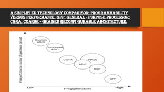
10.
A simplifi edtechnology comparison: programmability
versus performance. GPP, general - purpose processor;
CGRA, coarse - grained reconfi gurable architecture.
11.
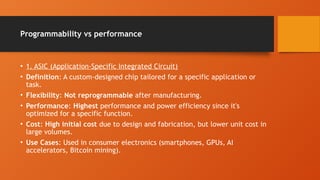
Programmability vs performance
•1. ASIC (Application-Specific Integrated Circuit)
• Definition: A custom-designed chip tailored for a specific application or
task.
• Flexibility: Not reprogrammable after manufacturing.
• Performance: Highest performance and power efficiency since it's
optimized for a specific function.
• Cost: High initial cost due to design and fabrication, but lower unit cost in
large volumes.
• Use Cases: Used in consumer electronics (smartphones, GPUs, AI
accelerators, Bitcoin mining).
12.
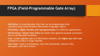
FPGA (Field-Programmable GateArray)
• Definition: A reconfigurable chip that can be programmed after
manufacturing using hardware description languages (HDLs).
• Flexibility: Highly flexible and reprogrammable for different applications.
• Performance: Slower than ASICs but faster than general-purpose processors
due to configurable hardware.
• Cost: Lower upfront cost (no fabrication needed), but higher per-unit cost
compared to ASICs in large volumes.
• Use Cases: Used in prototyping, real-time processing, telecom (5G),
aerospace, and data centers.
13.
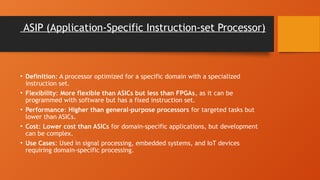
ASIP (Application-Specific Instruction-setProcessor)
• Definition: A processor optimized for a specific domain with a specialized
instruction set.
• Flexibility: More flexible than ASICs but less than FPGAs, as it can be
programmed with software but has a fixed instruction set.
• Performance: Higher than general-purpose processors for targeted tasks but
lower than ASICs.
• Cost: Lower cost than ASICs for domain-specific applications, but development
can be complex.
• Use Cases: Used in signal processing, embedded systems, and IoT devices
requiring domain-specific processing.
14.
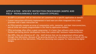
application - specificinstruction processors (ASIPs) and
field - programmable gate arrays (FPGAs).
• An ASIP is a processor with an instruction set customized for a specific application or domain.
• Custom instructions efficiently implemented in hard ware are often integrated into a base
processor with a basic instruction set.
• An FPGA typically contains an array of computation units, memories, and their interconnections,
and all three are usually programmable in the field by application builders.
• FPGA technology often offers a good compromise: It is faster than software while being more
flexible and having shorter development times than custom ASIC hardware implementations;
• like GPPs, they are offered as off - the - shelf devices that can be programmed without going
through chip fabrication. Because of the growing demand for reducing the time to market and the
increasing cost of chip fabrication, FPGAs are becoming more popular for implementing digital
designs.
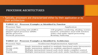
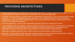
PROCESSOR ARCHITECTURES
• Therequirements space of an application is often large, and there is a range of implementation options. Thus, it
is usually difficult to associate a particular architecture with a particular application.
• In addition, some architectures combine different implementation approaches as seen in the PlayStation example
of Section 1.1 . There, the graphics processor consists of a four - element SIMD array of vector processing
functional units (FUs). Other SOC implementations consist of multiprocessors using very long instruction word
(VLIW) and/or superscalar processors.
• From the programmer ’ s point of view, sequential processors execute one instruction at a time.
• many processors have the capability to execute several instructions concurrently in a manner that is transparent
to the programmer, through techniques such as pipelining, multiple execution units, and multiple cores.
Pipelining is a powerful technique that is used in almost all current processor implementations.
• Pipelining is a powerful technique that is used in almost all current processor implementations.
• Instruction - level parallelism (ILP) means that multiple operations can be executed in parallel within a program.
ILP may be achieved with hardware, compiler, or operating system techniques.
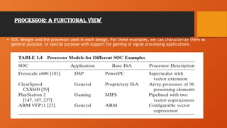
17.
Processor: A FunctionalView
• SOC designs and the processor used in each design. For these examples, we can characterize them as
general purpose, or special purpose with support for gaming or signal processing applications.
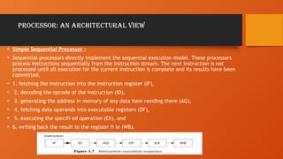
18.
Processor: An ArchitecturalView
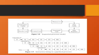
• Simple Sequential Processor :
• Sequential processors directly implement the sequential execution model. These processors
process instructions sequentially from the instruction stream. The next instruction is not
processed until all execution for the current instruction is complete and its results have been
committed.
• 1. fetching the instruction into the instruction register (IF),
• 2. decoding the opcode of the instruction (ID),
• 3. generating the address in memory of any data item residing there (AG),
• 4. fetching data operands into executable registers (DF),
• 5. executing the specifi ed operation (EX), and
• 6. writing back the result to the register fi le (WB).
19.
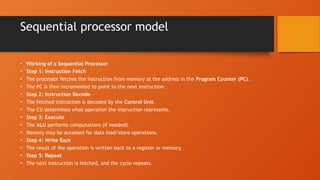
Sequential processor model
•Working of a Sequential Processor
• Step 1: Instruction Fetch
• The processor fetches the instruction from memory at the address in the Program Counter (PC).
• The PC is then incremented to point to the next instruction.
• Step 2: Instruction Decode
• The fetched instruction is decoded by the Control Unit.
• The CU determines what operation the instruction represents.
• Step 3: Execute
• The ALU performs computations (if needed).
• Memory may be accessed for data load/store operations.
• Step 4: Write Back
• The result of the operation is written back to a register or memory.
• Step 5: Repeat
• The next instruction is fetched, and the cycle repeats.
20.
Sequential processor model
•Applications
• Simple Embedded Systems – Used in microcontrollers for basic
tasks.
• Educational Purposes – Teaching basic computer architecture
concepts.
21.
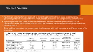
Pipelined Processor
• Pipeliningis a straightforward approach to exploiting parallelism that is based on concurrently
performing different phases (instruction fetch, decode, execution, etc.) of processing an instruction.
• Pipelining assumes that these phases are independent between different operations and can be
overlapped — when this condition does not hold, the processor stalls the downstream phases to enforce
the dependency.
• Thus, multiple operations can be processed simultaneously with each operation at a different phase of its
processing.
23.
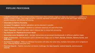
Pipeline processor
• Apipeline processor refers to a processing architecture where multiple stages (or steps) are arranged in a sequence to
handle a stream of data. Each stage performs a specific operation and passes the result to the next stage, allowing for
parallel execution and efficient processing.
• Advantages of Pipeline Processing
• Increased Throughput: Multiple operations can be executed in parallel.
• Efficient Resource Utilization: Hardware or software resources are used effectively.
• Faster Execution: Overall execution time is reduced due to concurrent processing.
• Key Features of a Pipelined Processor Model
• Instruction-Level Parallelism (ILP) – Multiple instructions are processed simultaneously in different pipeline stages.
• Stages of Execution – The instruction cycle is divided into stages such as Fetch, Decode, Execute, Memory Access, and
Write Back.
• Increased Throughput – While an individual instruction still takes the same time, multiple instructions are in progress at
once, reducing overall execution time.
• Potential Hazards – Pipeline execution introduces challenges like data hazards, control hazards, and structural
hazards.
24.
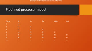
Pipelined processor model
CycleIF ID EX MEM WB
1 I1
2 I2 I1
3 I3 I2 I1
4 I4 I3 I2 I1
5 I5 I4 I3 I2 I1
6 I6 I5 I4 I3 I2
... .. .. .. .. ..
Example: Instruction Execution in a Pipeline
25.
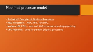
Pipelined processor model
•Real-World Examples of Pipelined Processors
• RISC Processors – ARM, MIPS, PowerPC.
• Modern x86 CPUs – Intel and AMD processors use deep pipelining.
• GPU Pipelines – Used for parallel graphics processing
27.
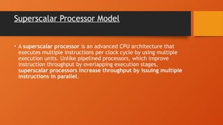
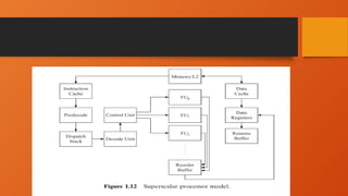
Superscalar Processor Model
•A superscalar processor is an advanced CPU architecture that
executes multiple instructions per clock cycle by using multiple
execution units. Unlike pipelined processors, which improve
instruction throughput by overlapping execution stages,
superscalar processors increase throughput by issuing multiple
instructions in parallel.
28.
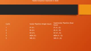
Cycle Scalar Pipeline(Single Issue)
Superscalar Pipeline (Dual
Issue)
1 IF (I1) IF (I1, I2)
2 ID (I1) ID (I1, I2)
3 EX (I1) EX (I1, I2)
4 MEM (I1) MEM (I1, I2)
5 WB (I1) WB (I1, I2)
Pipeline Comparison: Superscalar vs. Scalar
29.
Examples of SuperscalarProcessors
• Intel Pentium (First Superscalar x86 Processor)
• AMD Ryzen (Modern superscalar CPU)
• ARM Cortex-A Series (used in mobile devices)
• IBM PowerPC Processors (used in servers and gaming consoles)
• Apple M-Series Chips (highly optimized superscalar processors)
31.
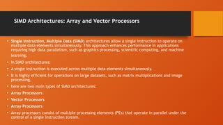
SIMD Architectures: Arrayand Vector Processors
• Single Instruction, Multiple Data (SIMD) architectures allow a single instruction to operate on
multiple data elements simultaneously. This approach enhances performance in applications
requiring high data parallelism, such as graphics processing, scientific computing, and machine
learning.
• In SIMD architectures:
• A single instruction is executed across multiple data elements simultaneously.
• It is highly efficient for operations on large datasets, such as matrix multiplications and image
processing.
• here are two main types of SIMD architectures:
• Array Processors
• Vector Processors
• Array Processors
• Array processors consist of multiple processing elements (PEs) that operate in parallel under the
control of a single instruction stream.
32.
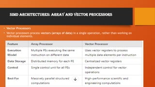
SIMD Architectures: Arrayand Vector Processors
• Vector Processors
• Vector processors process vectors (arrays of data) in a single operation, rather than working on
individual elements.
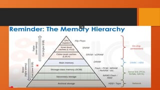
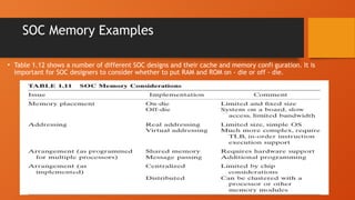
SOC Memory Examples
•Table 1.12 shows a number of different SOC designs and their cache and memory confi guration. It is
important for SOC designers to consider whether to put RAM and ROM on - die or off - die.
38.
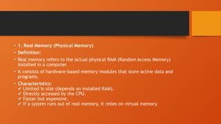
• 1. RealMemory (Physical Memory)
• Definition:
• Real memory refers to the actual physical RAM (Random Access Memory)
installed in a computer.
• It consists of hardware-based memory modules that store active data and
programs.
• Characteristics:
Limited in size (depends on installed RAM).
✔️
Directly accessed by the CPU.
✔️
Faster but expensive.
✔️
If a system runs out of real memory, it relies on virtual memory.
✔️
39.
• 2. VirtualMemory
• Definition:
• Virtual memory is a technique that allows a computer to use a part of the
storage (HDD/SSD) as additional memory when RAM is full.
• Managed by the operating system using a page file (Windows) or swap space
(Linux/macOS).
• Characteristics:
Provides the illusion of a larger memory space.
✔️
Slower than real memory (because it uses the disk).
✔️
Helps run large programs with limited RAM.
✔️
Uses paging and swapping techniques.
✔️
40.
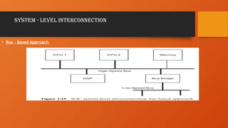
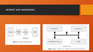
SYSTEM - LEVELINTERCONNECTION
• SOC technology typically relies on the interconnection of predesigned circuit modules (known as
intellectual property [IP] blocks) to form a complete system, which can be integrated onto a single
chip.
• SOC technology typically relies on the interconnection of predesigned circuit modules (known as
intellectual property [IP] blocks) to form a complete system, which can be integrated onto a single
chip.
• A well - designed interconnection scheme should have effi cient communication protocols.
• This facilitates interoperability between IP blocks designed by different people from different
organizations and encourages design reuse.
• SOC interconnect methods can be classified into two main approaches: buses and network - on - chip,
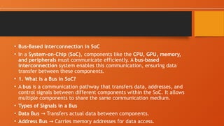
• Bus-Based Interconnectionin SoC
• In a System-on-Chip (SoC), components like the CPU, GPU, memory,
and peripherals must communicate efficiently. A bus-based
interconnection system enables this communication, ensuring data
transfer between these components.
• 1. What is a Bus in SoC?
• A bus is a communication pathway that transfers data, addresses, and
control signals between different components within the SoC. It allows
multiple components to share the same communication medium.
• Types of Signals in a Bus
• Data Bus Transfers actual data between components.
→
• Address Bus Carries memory addresses for data access.
→
.
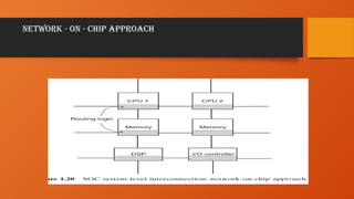
• 1. Whatis Network-on-Chip (NoC)?
• NoC (Network-on-Chip) is an advanced interconnect architecture where
multiple processing elements (PEs), memory units, and peripherals
communicate via a structured network instead of a shared bus or
crossbar.
• 🔹 Think of NoC like the Internet inside an SoC!
• Instead of a single bus, components communicate via routers and links
like packets in a network.
• Eliminates bus contention, increases parallelism, and scales efficiently
for multi-core and AI SoCs.
45.
AN APPROACH FORSOC DESIGN
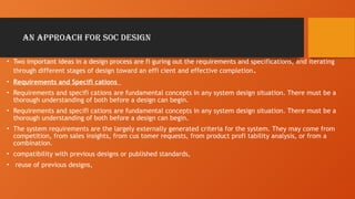
• Two important ideas in a design process are fi guring out the requirements and specifications, and iterating
through different stages of design toward an effi cient and effective completion.
• Requirements and Specifi cations
• Requirements and specifi cations are fundamental concepts in any system design situation. There must be a
thorough understanding of both before a design can begin.
• Requirements and specifi cations are fundamental concepts in any system design situation. There must be a
thorough understanding of both before a design can begin.
• The system requirements are the largely externally generated criteria for the system. They may come from
competition, from sales insights, from cus tomer requests, from product profi tability analysis, or from a
combination.
• compatibility with previous designs or published standards,
• reuse of previous designs,
46.
AN APPROACH FORSOC DESIGN
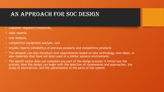
• customer requests/complaints,
• sales reports,
• cost analysis,
• competitive equipment analysis, and
• trouble reports (reliability) of previous products and competitive products
• The designer can also introduce new requirements based on new technology, new ideas, or
new materials that have not been used in a similar systems environment.
• The specifi cation does not complete any part of the design process; it initial izes the
process. Now the design can begin with the selection of components and approaches, the
study of alternatives, and the optimization of the parts of the system.
47.
Design Iteration
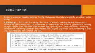
• Designis always an iterative process. So, the obvious question is how to get the very fi rst, initial
design.
• Initial Design: This is the fi rst design that shows promise in meeting the key requirements,
while other performance and cost criteria are not considered. For instance, processor or memory
or input/output (I/O) should be sized to meet high - priority real - time constraints. Promising
components and their parameters are selected and analyzed to provide an understanding of their
expected idealized performance and cost.


![Introduction to the Systems Approach
UNIT-1
• SYSTEM ARCHITECTURE: AN OVERVIEW
1. The past 40 years have seen amazing advances in silicon technology and resulting increases in
transistor density and performance.
2. In 1966, Fairchild Semiconductor [84] introduced a quad two input NAND gate with about 10
transistors on a die. In 2008, the Intel quad - core Itanium processor has 2 billion transistors
3. A system - on - chip (SOC) architecture is an ensemble of processors, memories, and
interconnects tailored to an application domain
4. A simple example of such an architecture is the Emotion Engine for the Sony PlayStation , which
has two main functions: behavior simulation and geometry translation. This system contains three
essential components: a main processor of the reduced instruction set computer (RISC) style
[118] and two vector processing units, VPU0 and VPU1, each of which contains four parallel
processors of the single instruction, multiple data (SIMD) stream style](https://image.slidesharecdn.com/systemonchip-250517044704-1fadd883/85/SYSTEM-approach-in-system-on-chip-architecture-2-320.jpg)
![SYSTEM - LEVEL INTERCONNECTION
• SOC technology typically relies on the interconnection of predesigned circuit modules (known as
intellectual property [IP] blocks) to form a complete system, which can be integrated onto a single
chip.
• SOC technology typically relies on the interconnection of predesigned circuit modules (known as
intellectual property [IP] blocks) to form a complete system, which can be integrated onto a single
chip.
• A well - designed interconnection scheme should have effi cient communication protocols.
• This facilitates interoperability between IP blocks designed by different people from different
organizations and encourages design reuse.
• SOC interconnect methods can be classified into two main approaches: buses and network - on - chip,](https://image.slidesharecdn.com/systemonchip-250517044704-1fadd883/85/SYSTEM-approach-in-system-on-chip-architecture-40-320.jpg)