This presentation willdiscuss about Power
converters
• Power conversion from high voltage AC (input)
supplies to low voltage DC(output)
• One DC voltage(input) to another DC voltage(ouput)
• Output > Input or Output < Input
but, Input Power > Output Power
(.... + losses in converter)
Linear Regulators
a simple, inexpensive circuit that produces a
quiet output voltage less than the input
voltage
Switching Regulators
more complex circuit that’s efficient,
compact, and versatile in its input/output
voltages
5.
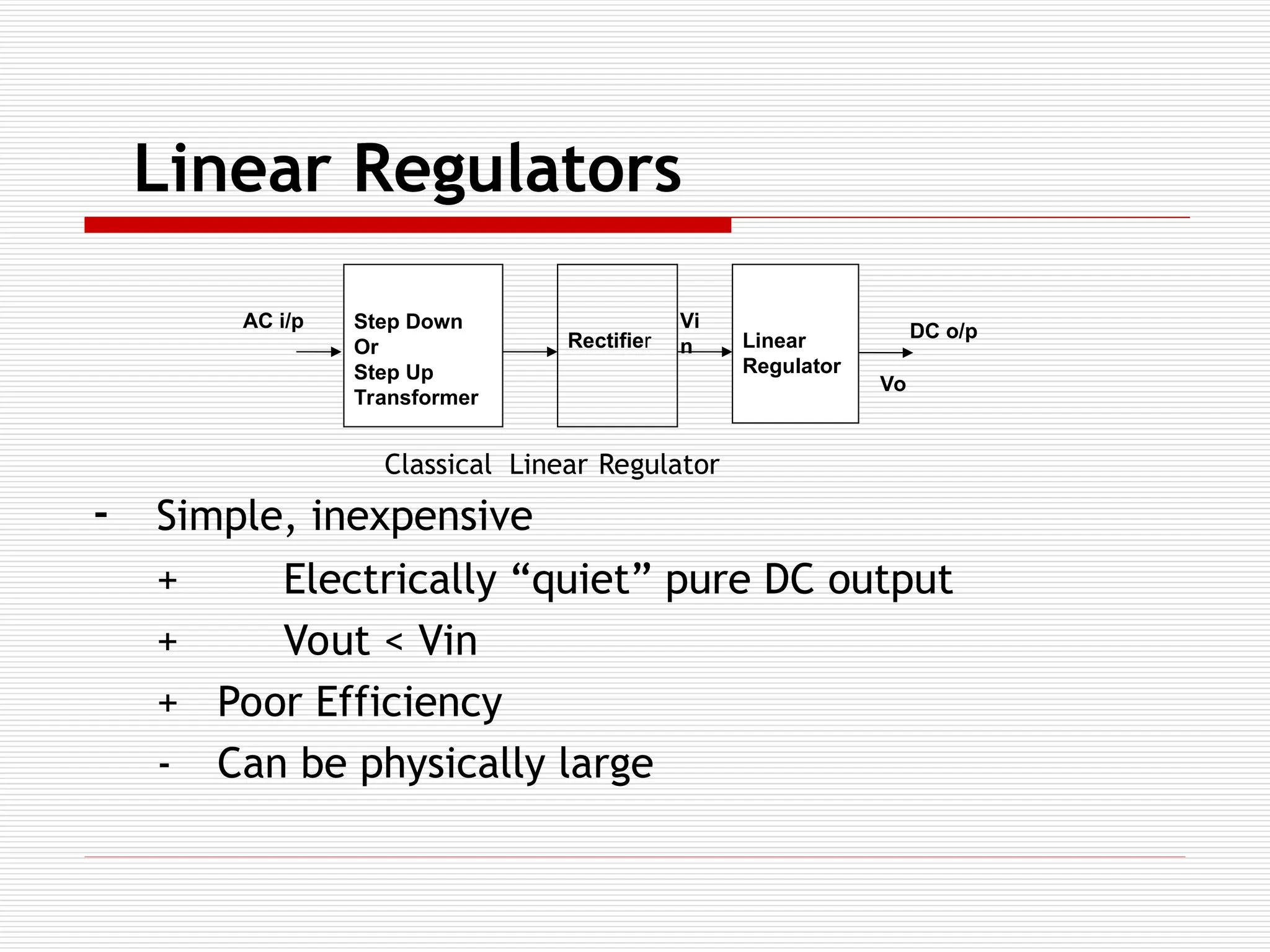
Linear Regulators
- Simple,inexpensive
+ Electrically “quiet” pure DC output
+ Vout < Vin
+ Poor Efficiency
- Can be physically large
Step Down
Or
Step Up
Transformer
Rectifier Linear
Regulator
DC o/p
AC i/p Vi
n
Vo
Classical Linear Regulator
6.
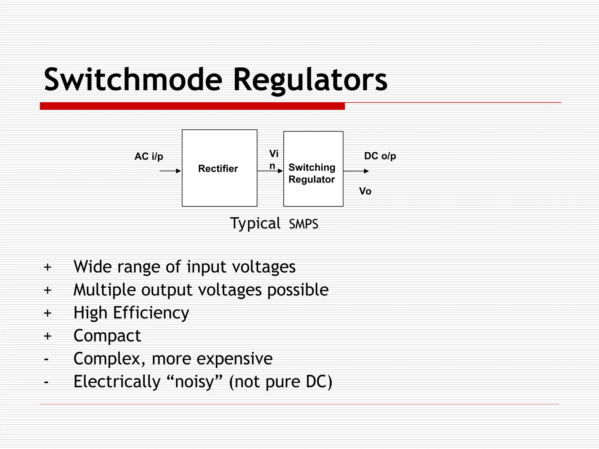
Switchmode Regulators
+ Widerange of input voltages
+ Multiple output voltages possible
+ High Efficiency
+ Compact
- Complex, more expensive
- Electrically “noisy” (not pure DC)
Rectifier Switching
Regulator
DC o/p
AC i/p Vi
n
Vo
Typical SMPS
7.
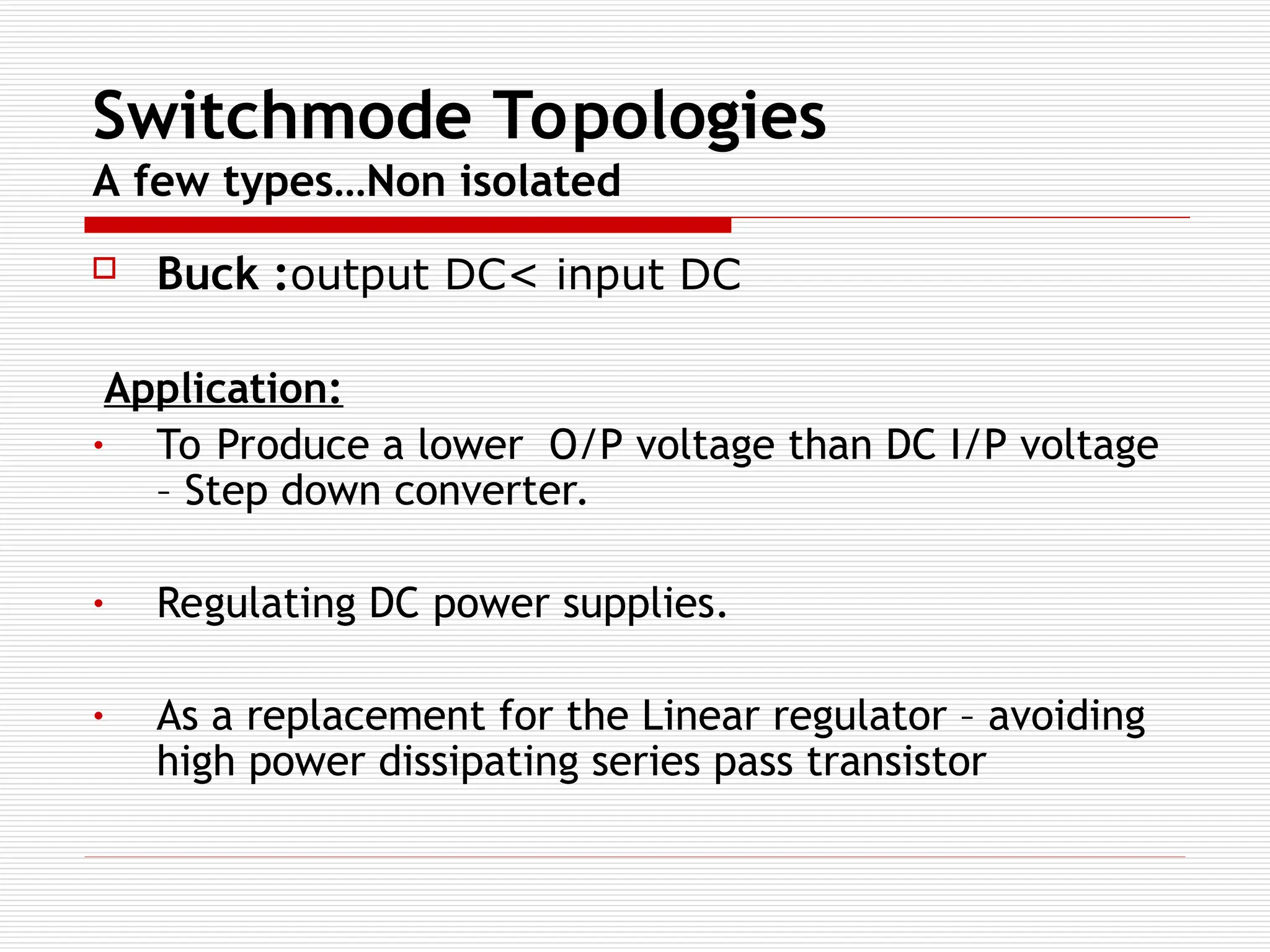
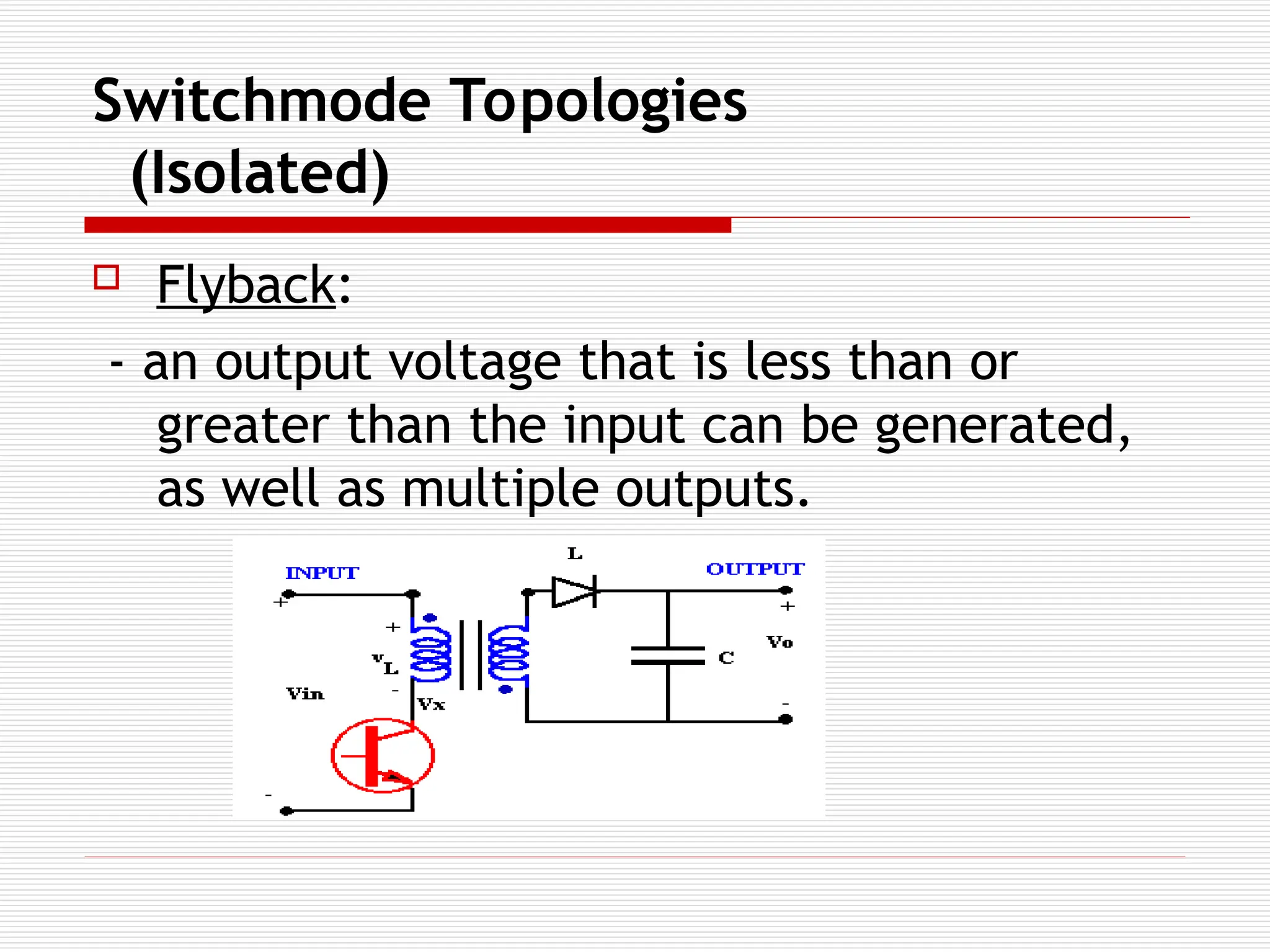
Switchmode Topologies
A fewtypes…Non isolated
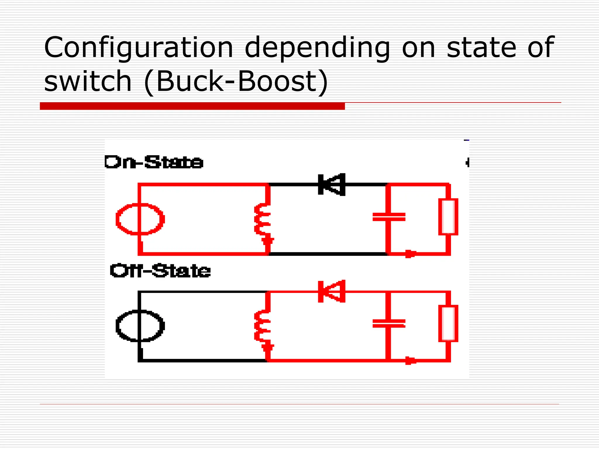
Buck :output DC< input DC
Application:
• To Produce a lower O/P voltage than DC I/P voltage
– Step down converter.
• Regulating DC power supplies.
• As a replacement for the Linear regulator – avoiding
high power dissipating series pass transistor
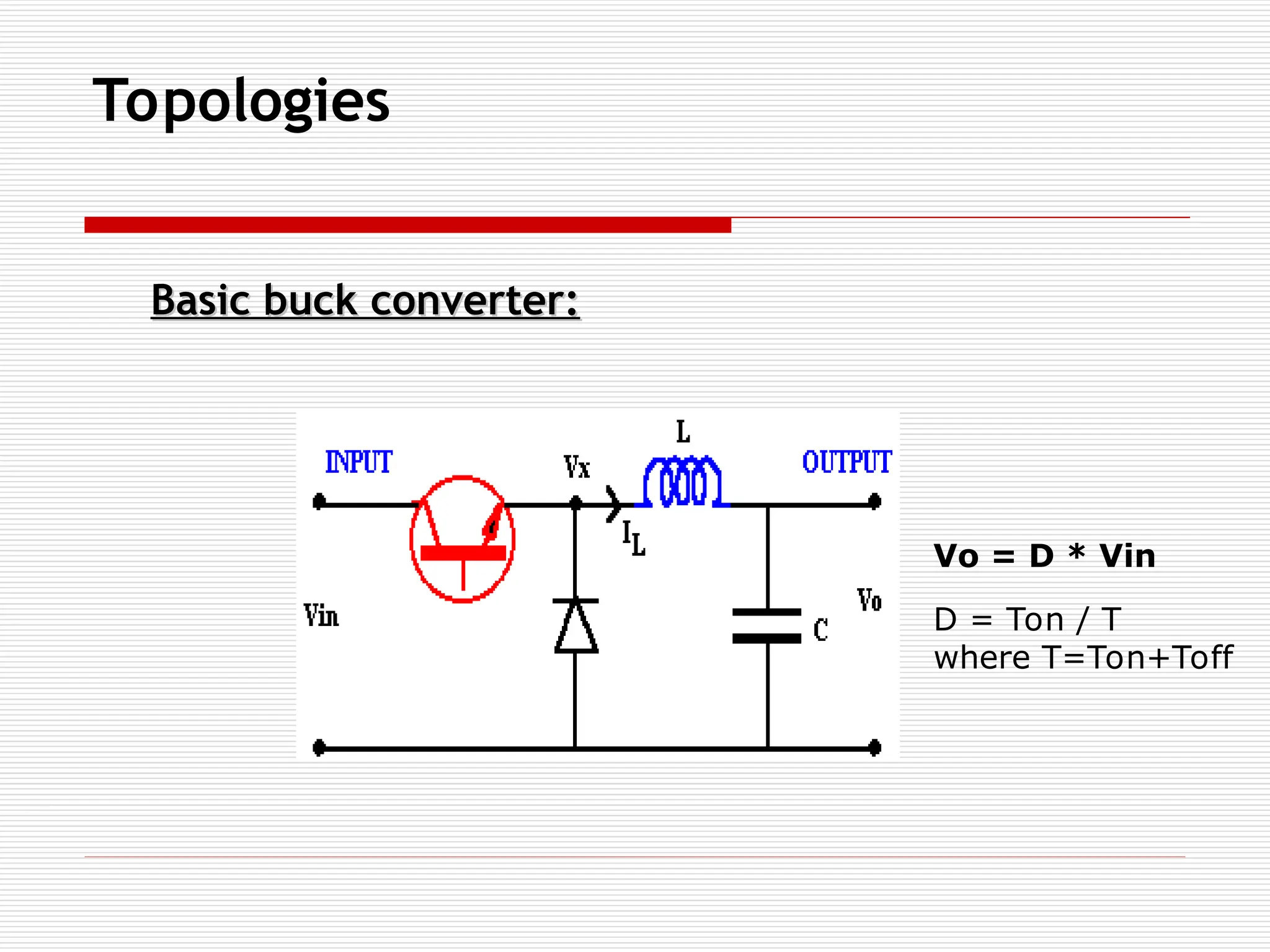
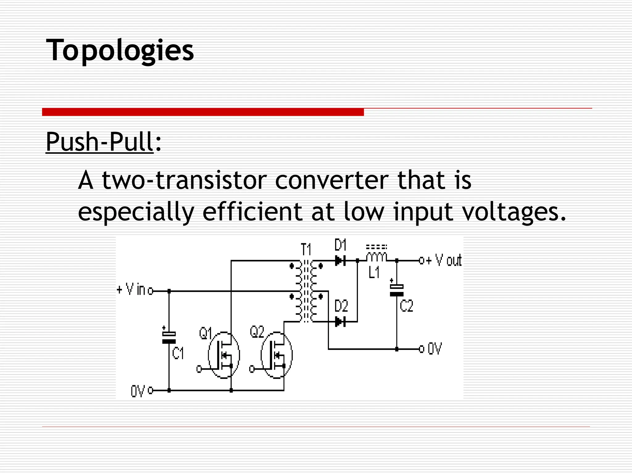
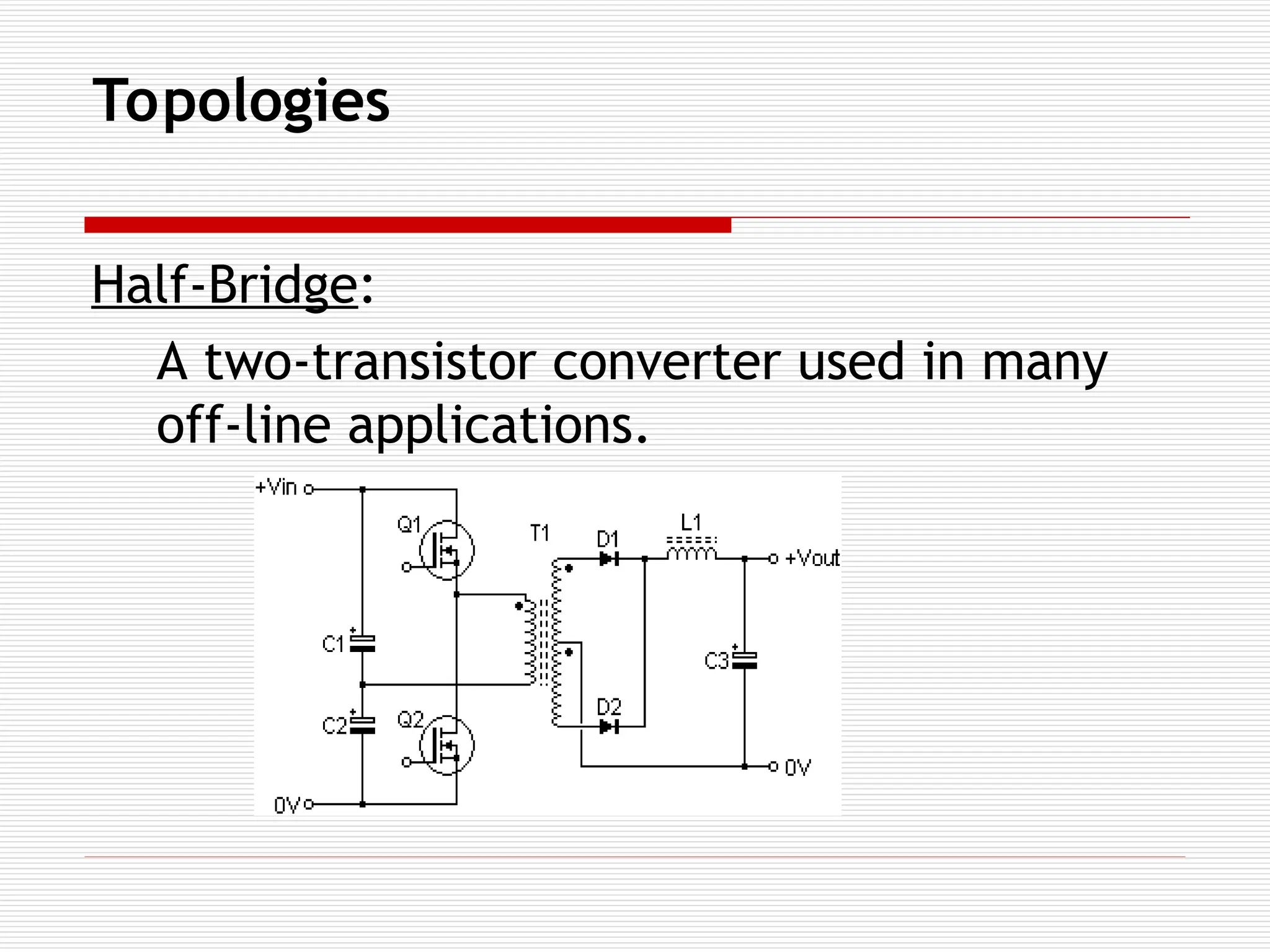
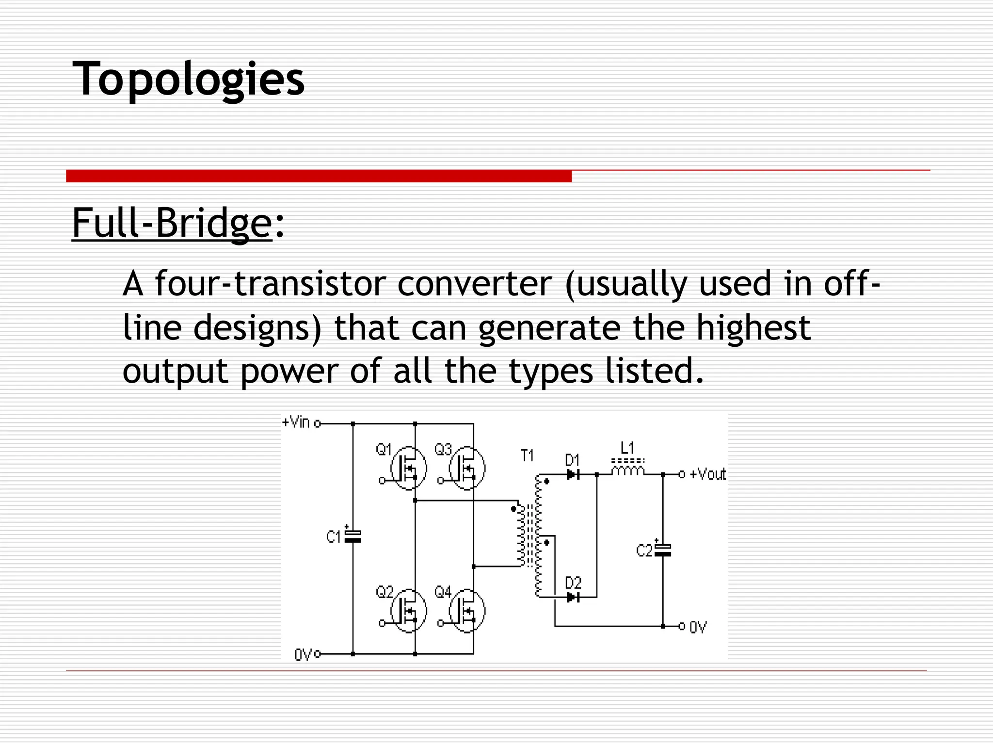
Topologies
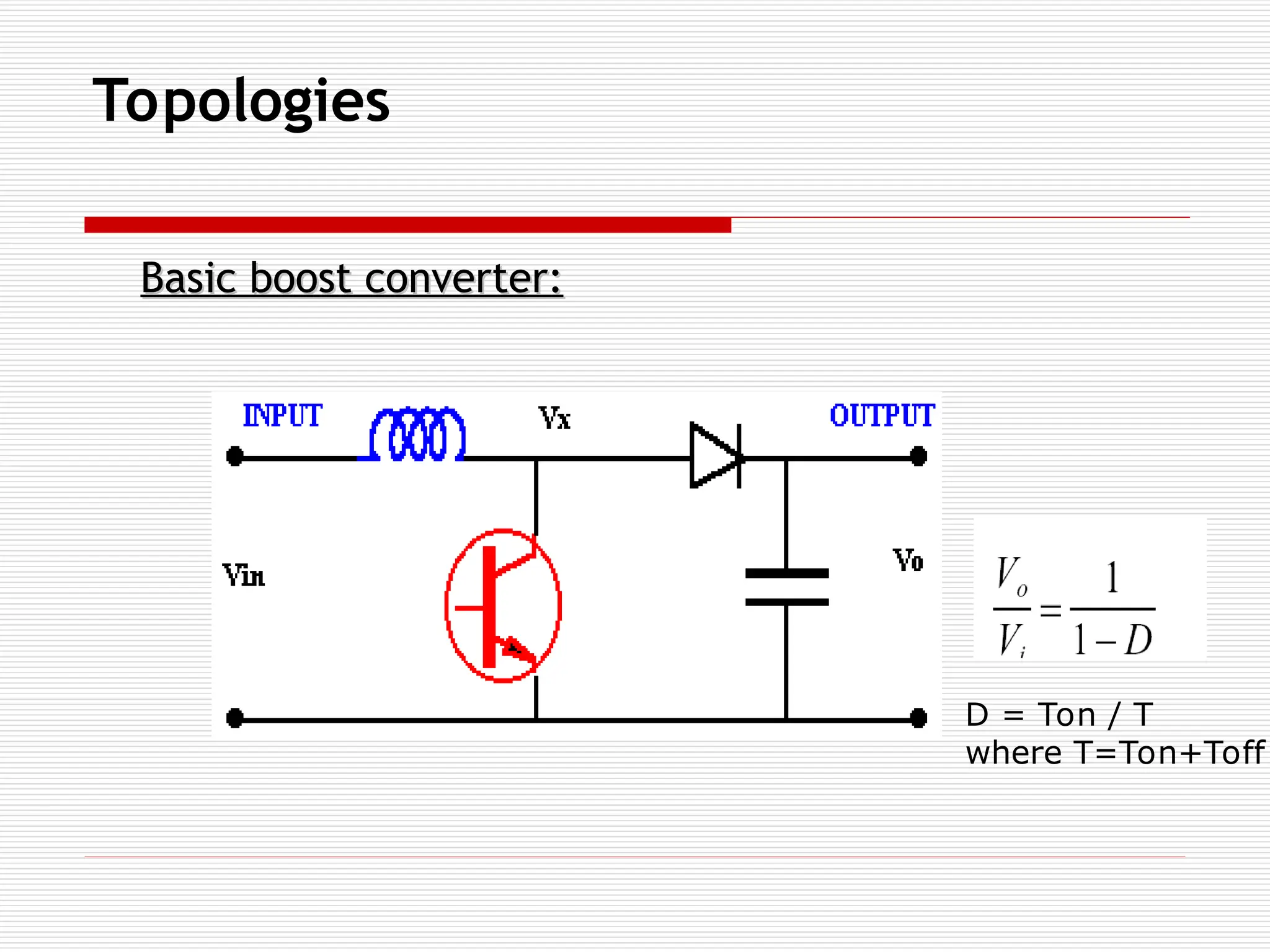
Boost :output DC > input DC
Application:
In battery operated devices, where the required
operational voltage is more than battery voltage
To achieve holdup time in critical embedded systems
Where high voltages are required e.g., TV picture
tubes, Cathode ray tube.
Isolated Converters -Requires
Transformer
The transformer functions as:
An isolation between the input and output
circuit.
Energy storage element.
Stepping up or down.
Providing Multiple outputs.
Modes of operationin converters:
Converters may be operated in two modes, according
to the current in its main magnetic component
[inductor or transformer]
Discontinuous mode:
- the current fluctuates during the cycle , goes down to
zero at the end of each cycle.
Continuous mode :
- the current fluctuates but never goes down to zero.
22.
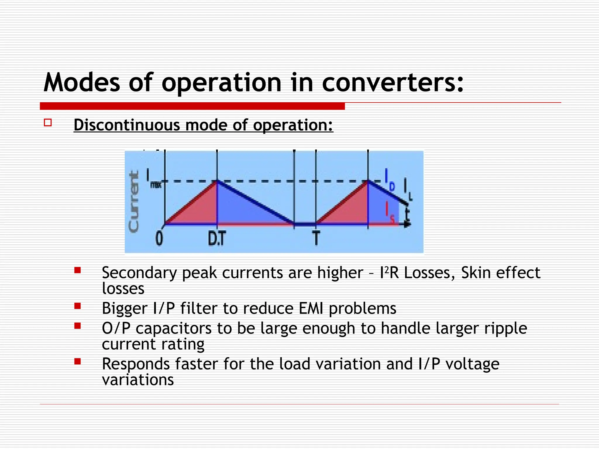
Modes of operationin converters:
Discontinuous mode of operation:
Secondary peak currents are higher – I2
R Losses, Skin effect
losses
Bigger I/P filter to reduce EMI problems
O/P capacitors to be large enough to handle larger ripple
current rating
Responds faster for the load variation and I/P voltage
variations
23.
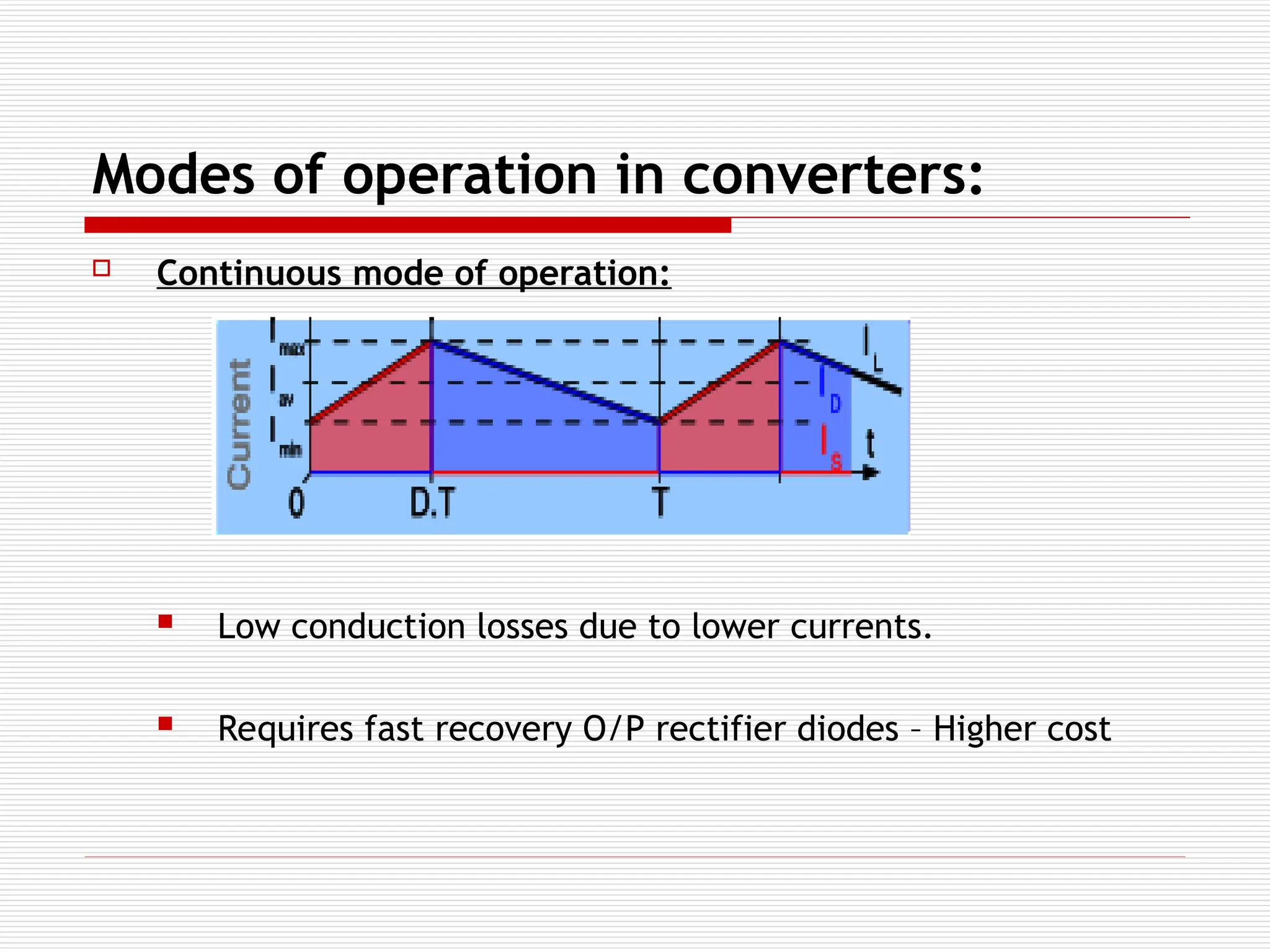
Modes of operationin converters:
Continuous mode of operation:
Low conduction losses due to lower currents.
Requires fast recovery O/P rectifier diodes – Higher cost
24.
Control techniques inconverters:
Voltage Mode Control:
The difference between the desired and actual
output voltages (error) controls the voltage
applied across the inductor.
Current Mode Control:
The difference between the desired and actual
output voltages (error) controls the peak
inductor current.
25.
Control techniques inconverters:
Voltage Mode Control:
Advantages:
- A single feedback loop is easier to design and analyze.
- Less noise, Less power loss, More resolution.
- A low-impedance power output provides better cross-
regulation for multiple output supplies.
- Provides Stable Operation.
26.
Control techniques inconverters:
Disadvantages:
- Any change in line or load must first be sensed as an
output change and then corrected by the feedback
loop. This usually means slow response.
- Compensation is further complicated by the fact that
the loop gain varies with input voltage
27.
Control techniques inconverters:
Current Mode Control:
Advantages:
- Responds immediately to input voltage changes.
- Since the Error Amplifier is used to command an output
current rather than voltage, the effect of the output
inductor is minimized .This allows both simpler
compensation and a higher gain bandwidth over a
comparable voltage-mode circuit.
28.
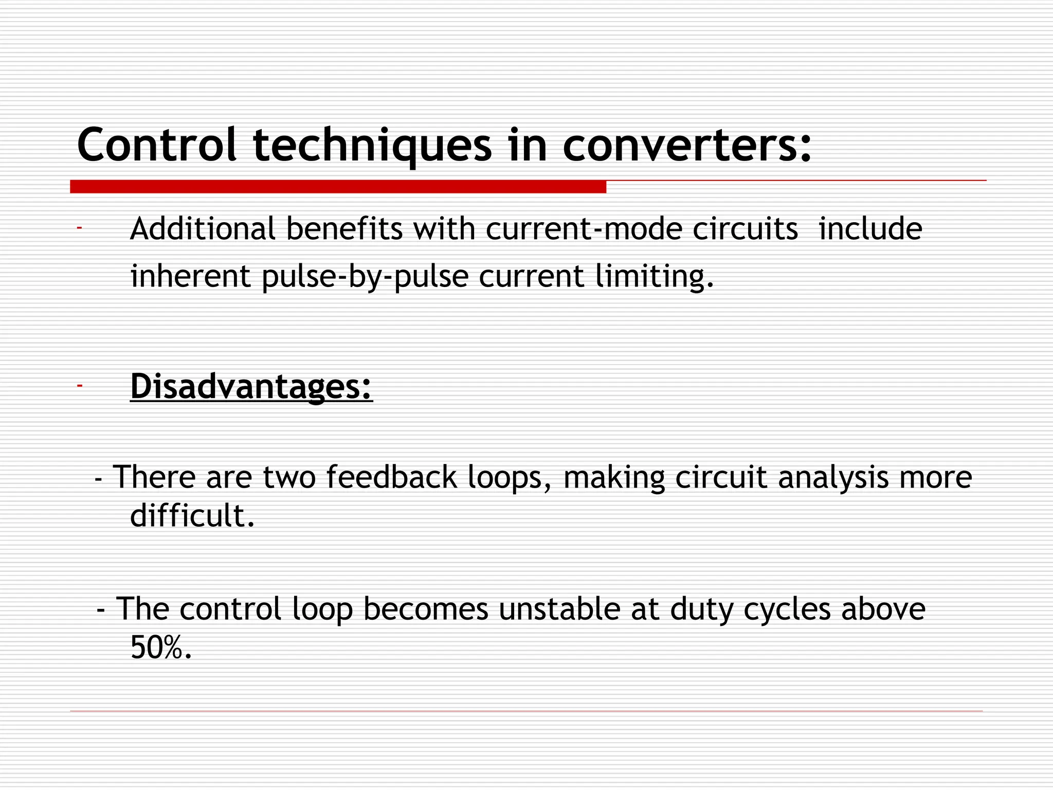
Control techniques inconverters:
- Additional benefits with current-mode circuits include
inherent pulse-by-pulse current limiting.
- Disadvantages:
- There are two feedback loops, making circuit analysis more
difficult.
- The control loop becomes unstable at duty cycles above
50%.


![Modes of operation in converters:
Converters may be operated in two modes, according
to the current in its main magnetic component
[inductor or transformer]
Discontinuous mode:
- the current fluctuates during the cycle , goes down to
zero at the end of each cycle.
Continuous mode :
- the current fluctuates but never goes down to zero.](https://image.slidesharecdn.com/pwrsupplyppt-250301050247-f0d0db82/75/Switch-Mode-Power-Supply-SMPS-Basics-ppt-21-2048.jpg)


![Vibe Coding vs. Spec-Driven Development [Free Meetup]](https://cdn.slidesharecdn.com/ss_thumbnails/vibecodingvsspecdrivendevelopment-251209105622-43f455e7-thumbnail.jpg?width=640&height=640&fit=bounds)


