This document discusses modeling and simulation of a semi-active suspension system for automobiles using a PID controller in MATLAB Simulink. It presents a quarter car model of a semi-active suspension system and develops state space equations to model vehicle body displacement, acceleration, wheel deflection, and other variables. The system is simulated in Simulink using PID control. Results show the PID controller improves performance over a passive system by reducing peak overshoots and settling times under both step and random road inputs. The semi-active suspension provides better ride quality and vehicle handling than a conventional passive suspension.

![ Some minor forces (including flex in the vehicle
body, movement and backlash in various linkages,
joints and gear system) are neglected for reducing
the complexity of the system because effect of these
forces is minimal due to low intensity. Hence these
left out for the system model.
Tyre material is considered as having damping
property as well as stiffness.
Mathematical Modelling of Semi-active Suspension System
Fig 1. Quarter car semi active suspension model
From fig.1 we have the following equations,
̈ ( ) ( ̇ ̇ ) ( )
̈ ( ) ( ̇ ̇ ) ( ) (1)
̈ ( ) ( ̇ ̇ ) ( ) ( ) (2)
After choosing State variables as,
( ) ( ) ( )
( ) ( ) ( )
( ) ̇ ( )
( ) ̇ ( )
From equation (1), we have
̇ ( ) [ ( ) ( )] [ ( )] ( ) (3)
From equation (2), we have
̇ ( ) [ ( ) ( )] [ ( )] [ ( )] ( ) (4)
Disturbance caused by road roughness,
( ) ̇ ( )
Therefore,
̇ ( ) ( ) ( )
̇ ( ) ( ) ( )
̇ ( )
( ) ( ) ( ) ( )
̇ ( )
( ) ( ) ( ) ( ) ( )
State space equation can be written as form,
̇( ) ( ) ( )
[
̇
̇
̇
̇
]=[ ][ ]+[ ]U +[ ]W
Where,
A=[ ] B=[ ] Bw=[ ]
C= [ ] , D= [0; 0; 0; 0]
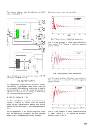
3. SIMULATION UNDER MATLAB SIMULINK
In this approach, system needs to be simulated for getting the
dynamic response. The entire suspension is simulated with
the application of MATLAB Simulink. In the last section
mathematical modelling of proposed system is done.
The Simulink library and logic is developed according to the
mathematical equations (1) and (2) and the entire system is
simulated in the Simulink as shown in Fig.2
Table 1. Parameters used in system simulation
S.N. Parameter Symbol Quatities
1 Mass of vehicle body Ms 504.5kg
2 Mass of the tyre and
suspention
Mu 62 kg
3 Coefficient of suspension
spring
Ks 13100
N/m
4 Coefficient of tyre material Kt 252000
N/m
5 Damping coefficient of the
dampers
Cs 400
N-s/m
821](https://image.slidesharecdn.com/suspensionsystem-140710020328-phpapp02/85/Suspension-system-2-320.jpg)