This document presents a study that aims to improve vehicle ride comfort using genetic algorithm optimization and a PI controller. The following key points are discussed:
1. A 7 degree-of-freedom full vehicle model is developed in MATLAB SIMULINK to study ride comfort.
2. A genetic algorithm is used to optimize the values of spring stiffness and damping coefficients for the front and rear passive suspension at different velocities.
3. A proportional-integral controller is also implemented to study its effect on ride comfort.
4. Comparisons of body acceleration and sprung mass displacement are made between the optimized suspension parameters, model with PI controller, and passive suspension system to evaluate ride performance improvements.
![ORIGINAL ARTICLE
Improvement of vehicle ride comfort using genetic
algorithm optimization and PI controller
A.E. Geweda a,*, M.A. El-Gohary b
, A.M. El-Nabawy a
, T. Awad b
a
Mechanical Power and Energy Department, Faculty of Engineering, Minia University, Minia, Egypt
b
Mechanical Engineering Department, Faculty of Engineering, Alexandria University, Alexandria, Egypt
Received 11 March 2017; revised 4 May 2017; accepted 7 May 2017
Available online 27 May 2017
KEYWORDS
Vehicle dynamics;
Full vehicle model;
Seven DOF model;
Genetic algorithm;
PI controller
Abstract In this paper a MATLAB SIMULINK model of seven Degrees Of Freedom (DOF) full
vehicle model is developed. Mathematical equations are obtained using Newton’
s second law and
free body diagram concept. Validation of the SIMULINK model is obtained to ensure that the
model is suitable for studying the ride comfort. A Genetic algorithm optimization technique is used
to find the optimum values of spring stiffness and damping coefficient for front and rear passive
suspension system of the seven DOF vehicle model at variable velocities which improve the perfor-
mance of the suspension system of the vehicle. Also Proportional Integral (PI) controller is imple-
mented to the model to study its effect on ride comfort. Comparison of the results for body
acceleration and sprung mass displacement of the optimized data of suspension parameters and
model with PI controller are illustrated. The results show that the optimized parameters and PI con-
troller give significant improvements of the vehicle ride performance over the passive suspension
system.
Ó 2017 Faculty of Engineering, Alexandria University. Production and hosting by Elsevier B.V. This is an
open access article under the CC BY-NC-ND license (http://creativecommons.org/licenses/by-nc-nd/4.0/).
1. Introduction
The major target of the vehicle suspension system is to enhance
the ride comfort and to provide good ride handling capability.
A vehicle suspension may be classified as passive suspension,
semi active suspension and active suspension system [1]. A
quality suspension must achieve a good behavior of the vehicle
and a degree of comfort depending on the interaction with the
uneven road surface [2]. Modeling of suspension systems is
very important as it can be used for studying the performance
of the ride comfort and road handling of the vehicle. There are
different methods of representation the model. State space
modeling, transfer function and MATLAB Simulink are used
to solve these models. There are different models used in this
field, quarter car model [2–4], half car model [5–7] and full
car model [8–11]. The performance of active suspension system
using Linear Quadratic Regulator (LQR) and Proportional
Integral Derivative (PID) techniques was compared with the
passive suspension system. Simulation is based on the mathe-
matical model by using MATLAB/SIMULINK software in
[3]. Mathematical half-car model was created in Matlab/Simu-
link. Results from simulations of model with original and opti-
mized suspension parameters were compared in [5]. Simulation
of active half car suspension model was done using MATLAB,
* Corresponding author.
E-mail address: eng_ahmed_geweda@yahoo.com (A.E. Geweda).
Peer review under responsibility of Faculty of Engineering, Alexandria
University.
Alexandria Engineering Journal (2017) 56, 405–414
HOSTED BY
Alexandria University
Alexandria Engineering Journal
www.elsevier.com/locate/aej
www.sciencedirect.com
http://dx.doi.org/10.1016/j.aej.2017.05.014
1110-0168 Ó 2017 Faculty of Engineering, Alexandria University. Production and hosting by Elsevier B.V.
This is an open access article under the CC BY-NC-ND license (http://creativecommons.org/licenses/by-nc-nd/4.0/).](https://image.slidesharecdn.com/improvementofvehicleridecomfortusinggeneticalgorithmoptimizationandpicontroller-191212090743/85/Improvement-of-vehicle-ride-comfort-using-geneticalgorithm-optimization-and-pi-controller-1-320.jpg)
![Simulink and a comparison between controllers such as
classical PID controller; self-tunable fuzzy inference system
(STFIS) controller and the passive system controller were
founded in [6]. The full car suspensions for passive and active
one with PID or Fuzzy controls were simulated using
MATLAB/SIMULINK at [12]. The results indicated that the
active with PID and fuzzy controls suspension systems were
better than the passive system. An active suspension for the
Quarter/Half/Full car model of car was developed by [13] to
improve its performance by using a PID controller. Optimiza-
tion was also applied to one of the these types as in [14] who
made an investigation to determine the spring and damper set-
tings that will ensure optimal ride comfort of vehicle for differ-
ent speeds using Design of Experiment Method (DOE) for
seven degrees of freedom full car model.
This paper is organized as follows; Full car model is
obtained in Section 2. Mathematical equations are presented
in Section 3. In Section 4 the MATLAB, Simulink model is
built. The road profiles used in this paper are given on
Section 5. Section 6 shows the optimization and controller.
Results and discussion of validation are obtained in Section 7.
Section 8 presents the conclusions of the paper. An Appendix
A is given at the end of the paper.
2. Full car model
Fig. 1 shows a full car model with seven degrees of
freedom system considered for analysis [11]. It is consisting
of sprung mass, Ms referring to the part of the car that is
supported on springs and un-sprung mass which refers to the
mass of the wheel assembly. The suspensions between the
sprung mass and un-sprung masses are modeled as linear
viscous dampers and spring components. The tire has been
replaced with its equivalent stiffness and tire damping
is neglected as it’s influence on tire behavior is negligible
[9,11 and 12].
3. Mathematical modeling
3.1. Mathematical equations
Using the Newton’s second law of motion and free body dia-
gram concept; the following seven equations of motion are
derived.
For vehicle body bounce motion (Sprung Mass):
MsZ
ÁÁ
Cg ¼ ðÀKsr1 À Ksl1 À Ksr2 À Ksl2ÞZcg
þ ðÀCsr1 À Csl1 À Csr2 À Csl2ÞZ
Á
cg
þ ðKsr1a þ Ksl1a À ksr2b À ksl2bÞh
þ ðCsr1a þ Csl1a À Csr2b À Csl2bÞ h
Á
þ ðKsr1c À Ksl1d þ Ksr2c À Ksl2dÞu
þ ðCsr1c À Csl1d þ Csr2c À Csl2dÞ u
Á
þ Ksr1Zwr1 þ Ksl1Zwl1 þ Ksr2Zwr2 þ Ksl2Zwl2
þ Csr1Z
Á
wr1 þ Csl1Z
Á
wl1 þ Csr2Z
Á
wr2 þ Csl2Z
Á
wl2 ð1Þ
For vehicle body pitching motion (Sprung Mass):
Iyy h
ÁÁ
¼ ðKsr1a þ Ksl1a À ksr2b À Ksl2bÞZcg
þ ðCsr1a þ Csl1a À Csr2b À Csl2bÞZ
Á
cg
þ ðÀKsr1a2
À Ksl1a2
À Ksr2b2
À Ksl2b2
Þh
þ ðCsr1a2
À Csl1a2
À Csr2b2
À Csl2b2
Þ h
Á
þ ðÀKsr1ac þ Ksl1ad þ Ksr2bc À Ksl2bdÞu
þ ðÀCsr1ac þ Csl1ad þ Csr2bc À Csl2bdÞ u
Á
ÀKsr1aZwr1
À Ksl1aZwl1 þ Ksr2bZwr2 þ Ksl2bZwl2 À Csr1aZ
Á
wr1
À Csl1aZ
Á
wl1 þ Csr2bZ
Á
wr2 þ Csl2bZ
Á
wl2 ð2Þ
Nomenclature
a distance from CG to front wheel, m
b distance from CG to rear wheel, m
Csl1 damping coefficient of front left damper, N-s/m
Csl2 damping coefficient of rear left damper, N-s/m
Csr1 damping coefficient of front right damper, N-s/m
Csr2 damping coefficient of rear right damper, N-s/m
c distance from CG to right wheel, m
d distance from CG to left wheel, m
Ixx moment of Inertia about X-X axis, kg-m2
Iyy moment of Inertia about Y-Y axis, kg-m2
Ksl1 spring stiffness of front left suspension, N/m
Ksl2 spring stiffness of rear left suspension, N/m
Ksr1 spring stiffness of front right suspension, N/m
Ksr2 spring stiffness of rear right suspension, N/m
Kwl1 spring stiffness of front left tire, N/m
Kwl2 spring stiffness of rear left tire, N/m
Kwr1 spring stiffness of front right tire, N/m
Kwr2 spring stiffness of rear right tire, N/m
MS mass of vehicle, kg
Mwl1 mass of front left wheel, kg
Mwl2 mass of rear left wheel, kg
Mwr1 mass of front right wheel, kg
Mwr2 mass of rear right wheel, kg
Zcg displacement of CG of vehicle body, m
Zrl1 road input to front left wheel, m
Zrl2 road input to rear left wheel, m
Zrr1 road input to front right wheel, m
Zrr2 road input to rear right wheel, m
Zwl1 displacement of front left wheel, m
Zwl2 displacement of rear left wheel, m
Zwr1 displacement of front right wheel, m
Zwr2 displacement of rear right wheel, m
h pitch angle of the body at CG, degree
U roll angle of the body at CG, degree
406 A.E. Geweda et al.](https://image.slidesharecdn.com/improvementofvehicleridecomfortusinggeneticalgorithmoptimizationandpicontroller-191212090743/85/Improvement-of-vehicle-ride-comfort-using-geneticalgorithm-optimization-and-pi-controller-2-320.jpg)
![For vehicle body rolling motion (Sprung Mass)
Ixx u
ÁÁ
¼ ðKsr1c À Ksl1d þ Ksr2c À Ksl2dÞZcg
þ ðCsr1c À Csl1d þ Csr2c À Csl2dÞ Z
Á
cg
þ ðÀksr1ac þ Ksl1ad þ Ksr2bc À Ksl2bdÞh
þ ðCsr1ac þ Csl1ad þ Csr2bc À Csl2bdÞ h
Á
þ ðÀKsr1c2
À Ksl1d2
À Ksr2c2
À Ksl2d2
Þu
þ ðÀCsr2c2
À Csl2d2
À Csr2c2
À Csl2d2
Þ u
Á
ÀKsr1cZwr1
þ Ksl1dZwl1 À Ksr2cZwr2 þ Ksl2dZwl2 À Csr1cZ
Á
wr1
þ Csl1dZ
Á
wl1 À Csr2cZ
Á
wr2 þ Csl2dZ
Á
wl2 ð3Þ
For front right wheel (Un-sprung Mass):
Mwr1Z
ÁÁ
wr1 ¼ Ksr1ðZcg À Zwr1 À ah À cuÞ
þ Csr1ðZ
Á
cg À Z
Á
wr1 À a h
Á
Àc u
Á
Þ þ Kwr1ðZrr1 À Zwr1Þ
ð4Þ
For front left wheel (Un-sprung Mass):
Mwl1Z
ÁÁ
wl1 ¼ Ksl1ðZcg À Zwl1 À ah þ duÞ
þ Csl1ðZ
Á
cg À Z
Á
wl1 À a h
Á
þd u
Á
Þ þ Kwl1ðZrl1 À Zwl1Þ
ð5Þ
For rear right wheel (Un-sprung Mass):
Mwr2Z
ÁÁ
wr2 ¼ Ksr2ðZcg À Zwr2 þ bh À cuÞ
þ Csr2ðZ
Á
cg À Z
Á
wr2 þ b h
Á
Àc u
Á
Þ þ Kwr2ðZrr2 À Zwr2Þ
ð6Þ
For rear left wheel (Un-sprung Mass):
Mwl2Z
ÁÁ
wl2 ¼ Ksl2ðZcg À Zwl2 þ bh þ duÞ
þ Csl2ðZ
Á
cg À Z
Á
wl2 þ b h
Á
þd u
Á
Þ þ Kwl2ðZrl2 À Zwl2Þ
ð7Þ
Fig. 1 Full car model.
Table 1 Fixed parameters of full car model [11].
Ms = 1200 (kg) a = b = 1.5 (m) C = d = 1 (m)
Mwr2 = Mwl2 = 60(kg) Kwr1 = Kwl1 = 30000 (N/m) Kwr2 = Kwl2 = 30,000 (N/m)
Mwr1 = Mwl1 = 60 (kg) Ixx = 4000 (kg-m2
) Iyy = 950 (kg-m2
)
Fig. 2 Flow chart of full vehicle model.
Improvement of vehicle ride comfort 407](https://image.slidesharecdn.com/improvementofvehicleridecomfortusinggeneticalgorithmoptimizationandpicontroller-191212090743/85/Improvement-of-vehicle-ride-comfort-using-geneticalgorithm-optimization-and-pi-controller-3-320.jpg)
![3.2. Fixed parameters of full car model
The full car model with seven DOF used in this study has the
following fixed parameters. Suspension spring stiffness are
55,000 N/m for front suspension system and 25,000 N/m for
rear suspension as in [11]. Damping coefficient is 4000 N-s/m
for front suspension system and 1000 N-s/m for rear suspen-
sion system as in [11]. The fixed parameters of the full car
model are shown in Table 1.
4. Matlab Simulink model
Mathematical full-car model is created using Matlab/Simulink.
Fig. 2 shows a flow chart from the input (road profile) to the
wheels (front right and left) to the car body and finally the
outputs (vertical, pitch and roll motions). The full vehicle
subsystem model using Matlab Simulink is shown in
Appendix A.
5. Road profiles used in the study
There are two kinds of road profiles that used as input to
the Simulink model in this study. The first one is a unit
step input with 5 s delay as shown in Fig. 3 as in [12]. This
road profile is used to validate the developed model. The
second road input is a bump road surface of half sine wave
shape as shown in Fig. 4 and the model in this study is
considered to move with variable velocities from 20 to
120 km/h.
5.1. Validation of Simulink model using step input with delay
Fig. 5 shows the effects of changing the value of spring stiff-
ness on the body acceleration of the model as obtained by a
response of SIMULINK model when the input to the model
is unit step input with 5 (s) step time as compared to that of
[12] using the same data of [12].
From Fig. 5, it can be noted that the curve of the body
acceleration of the Simulink model is in excellent agreement
with the model as given in Ref. [12]. In both acceleration
curves, the settling time is 6.5 (s) and the peak value is 1.5
(m/s2
). So the developed model can be used in the study for
further investigations.
Fig. 3 Unit step input with delay.
Fig. 4 Road hump.
Fig. 5 Body acceleration vs. Time.
408 A.E. Geweda et al.](https://image.slidesharecdn.com/improvementofvehicleridecomfortusinggeneticalgorithmoptimizationandpicontroller-191212090743/85/Improvement-of-vehicle-ride-comfort-using-geneticalgorithm-optimization-and-pi-controller-4-320.jpg)
![7. Results and discussion
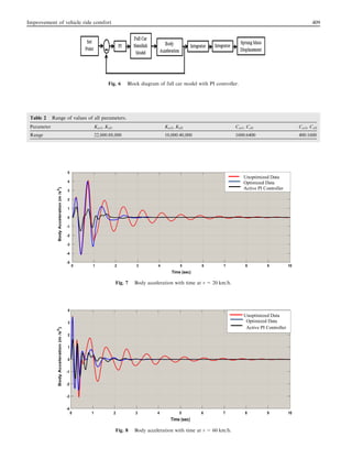
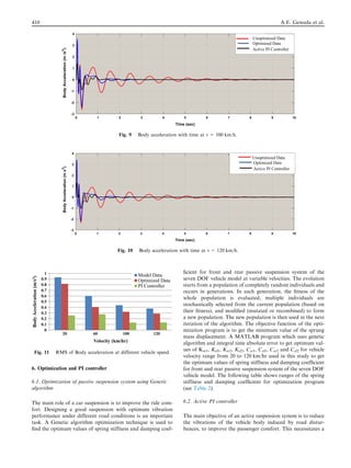
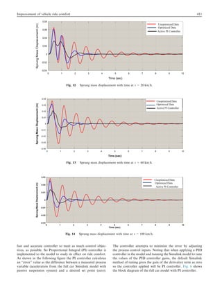
7.1. Body acceleration results
Figs. 7–11 show the response of the body acceleration of the
model at 20, 60, 100 and 120 km/h for unoptimized data of
the model reported in [11], passive optimized data and model
with active PI controller. It is observed that the body acceler-
ation using optimized data and model with controller is less
than the body acceleration using unoptimized data of the
model in all velocities.
As shown in the above figures the performance of the body
acceleration has been improved as following.
At v = 20 km/h the improvement in Root Mean Square
(RMS) value of body acceleration when using optimized data
is 12.4% and it’s 72.1% in case of using active PI controller. At
v = 60 km/h the optimized data improved the RMS value of
body acceleration by 32.5% and active PI controller improved
it by 54%. The improvement of the RMS value of body accel-
eration is 26.2% in case of optimized data and 69.5% in case
of active PI controller at v = 100 km/h. Finally at
v = 120 km/h the improvement in the RMS value of body
acceleration when optimized data used is 23.7% and 64.5%
when active PI controller used.
7.2. Sprung mass displacement results
The following figures show the response of sprung mass dis-
placement of the model at 20, 60, 100 and 120 km/h using
unoptimized data of the model reported in [11], optimized data
and model with controller. It is founded that the sprung mass
displacement using optimized data and model with controller
is less than the sprung mass displacement using unoptimized
data of the model in all velocities (see Figs. 12–16).
As shown in the above figures the performance of the sprung
mass displacement has also been improved as following.
At v = 20 km/h the improvement in RMS value of sprung
mass displacement when using optimized data is 22.4% and
it’s 45.2% in case of using active PI controller. At
v = 60 km/h the optimized data improved the RMS value of
sprung mass displacement by 42.8% and active PI controller
improved it by 58.8%. The improvement of the RMS value
of sprung mass displacement is 43.1% in case of optimized
data and 62.8% in case of active PI controller at
v = 100 km/h. Finally at v = 120 km/h the improvement in
RMS value of sprung mass displacement when optimized data
used is 42.8% and 63% when active PI controller used.
8. Conclusion
In this work the mathematical equations of the full vehicle
model with seven DOF are put forward using newton’s second
law then a MATLAB SIMULINK model developed. Also it
was attempted to study the effect of the optimum values of
spring stiffness and damping coefficient and PI controller on
body acceleration and sprung mass displacement of seven
DOF vehicle model at different velocities. Genetic algorithm
optimization technique is used to find the optimum values of
spring stiffness and damping coefficient for front and rear sus-
pension system. PI controller is also implemented to the
model. The results show that the optimized parameters and
PI controller give significant improvements on body accelera-
tion and sprung mass displacement over the passive suspension
system. For body acceleration the improvement was 12.4%,
32.5%, 26.2% and 23.7% at velocities 20, 60, 100 and
120 km/h respectively when using optimized data and it was
72.1%, 45%, 69.5% and 64.5% at velocities 20, 60, 100 and
120 km/h respectively when using PI controller. For sprung
mass displacement the improvement was 22.4%, 42.8%,
34.1% and 42.8% at velocities 20, 60, 100 and 120 km/h
respectively when using optimized data and it was 45.2%,
58.8%, 62.8% and 63% at velocities 20, 60, 100 and 120 km/
h respectively when using PI controller.
Unoptimized Data
Optimized Data
Active PI Controller
Fig. 15 Sprung mass displacement with time at v = 120 km/h.
0
0.002
0.004
0.006
0.008
0.01
0.012
0.014
0.016
20 60 100 120
SprungMassDislacement(m)
Velocity (km/hr)
Model Data
Optimized Data
PI Controller
Fig. 16 RMS of Sprung mass displacement at different vehicle
speed.
412 A.E. Geweda et al.](https://image.slidesharecdn.com/improvementofvehicleridecomfortusinggeneticalgorithmoptimizationandpicontroller-191212090743/85/Improvement-of-vehicle-ride-comfort-using-geneticalgorithm-optimization-and-pi-controller-8-320.jpg)
![Appendix A
References
[1] S. Qamar, L. Khan and Z. Qamar, Online adaptive full car
active suspension control using B-spline fuzzy-neural network,
in: IEEE 11th International Conference on Frontiers of
Information Technology, Serena Hotel Ramna5, Khayaban-e-
SuhrawardyKhayaban-e-Suhrwardy, Islamabad, Pakistan,
2013, pp. 205–210.
[2] A. Florin, M.R.I. Cozmin, P. Liliana, Pasive suspension
modeling using matlab, quarter car model, input signal step
type, TEHNOMUS - New Technologies and Products in
Machine Manufacturing Technologies, Suceava, Romania,
2013, pp. 258–263.
[3] R. Darus, N.I. Enzai, Modeling and control active suspension
system for a quarter car model, in: IEEE International
Conference on Science and Social Research, Kuala Lumpur,
Malaysia, December 5–7, 2010, pp. 1203–1206.
[4] E.A. Sa´ nchez, A quarter-car suspension system: car body mass
estimator and sliding mode control, in: Iberoamerican
Conference on Electronics Engineering and Computer Science,
vol. 7, Iberoamerican, 2013, pp. 208–214.
Improvement of vehicle ride comfort 413](https://image.slidesharecdn.com/improvementofvehicleridecomfortusinggeneticalgorithmoptimizationandpicontroller-191212090743/85/Improvement-of-vehicle-ride-comfort-using-geneticalgorithm-optimization-and-pi-controller-9-320.jpg)
![[5] V. Gogaa, M. Klu´ cik, Optimization of vehicle suspension
parameters with use of evolutionary computation, Proc. Eng.
48 (2012) 174–179.
[6] W. Abbas, A. Emam, S. Badran, M. Shebl, O. Abouelatta,
Optimal seat and suspension design for a half-car with driver
model using genetic algorithm, Intell. Contr. Autom. 4 (2013)
199–205.
[7] H. Souilem, S. Mehjoub, N. Derbel, Intelligent control for a
half-car active suspension by self-tunable fuzzy inference system,
Int. J. Fuzzy Syst. Adv. Appl. 2 (2015) 9–15.
[8] L. Khan, S. Qamar, M.U. Khan, Neuro-fuzzy wavelets based
network for full car active suspension system, in: IEEE
International Conference on Emerging Technologies (ICET),
Islamabad, Pakistan, 08 Oct – 09 Oct 2012.
[9] J. Wang, C. Song, Computer simulation on fuzzy control of
semi-active suspension system based on the whole vehicle, Int. J.
Multimedia Ubiquitous Eng. 8 (6) (2013) 217–228.
[10] S. Qamar, L. Khan, S. Ali, Adaptive B-spline based neuro-fuzzy
control for full car active suspension system, Middle-East J. Sci.
Res. 16 (10) (2013) 1348–1360.
[11] A. Mitra, N. Benerjee, H.A. Khalane, M.A. Sonawane, D.R.
Joshi, G.R. Bagul, Simulation and Analysis of Full Car Model
for various Road profile on a analytically validated MATLAB/
SIMULINK model, IOSR Journal of Mechanical and Civil
Engineering (IOSR-JMCE), 2013, pp. 22–33.
[12] M.M.M. Salem, Full car model active suspension system with
PID and fuzzy controls to improve ride comfort, J. Am.Sci. 9
(12) (2013) 633–645.
[13] T. Nath, S. Kumar and Meerut, Quarter/half/full car models for
active suspension (with PID controller), in: IEEE International
Conference on Recent Trends in Engineering & Technology
(ICRTET), Madras Institute of Technology, Anna University
Chennai, Tamil Nadu, India, 2012, pp. 286–290.
[14] S. Mostaani, D. Singh, K. Firouzbakhsh, M. T. Ahmadian,
Optimization of a passive vehicle suspension system for ride
comfort enhancement with different speeds based on DOE
method, in: Proc. of Int. Colloquiums on Computer Electronics
Electrical Mechanical and Civil, Kerala, India, 20–21 September
2011, pp. 149–154.
414 A.E. Geweda et al.](https://image.slidesharecdn.com/improvementofvehicleridecomfortusinggeneticalgorithmoptimizationandpicontroller-191212090743/85/Improvement-of-vehicle-ride-comfort-using-geneticalgorithm-optimization-and-pi-controller-10-320.jpg)


