The seminar report discusses the development and advantages of non-pneumatic airless tires, specifically the 'tweel' design, which offers significant safety improvements, environmental benefits, and enhanced performance over traditional pneumatic tires. The report highlights the unique structure of the tweel, which eliminates the risk of blowouts and reduces landfill waste due to its retreadable nature. It concludes that further research and production of airless tires should be prioritized to modernize automotive designs and improve safety for everyday users.


![CHAPTER 1
INTRODUCTION
PROBLEM IN CONVENTOINAL TYRE :
LOWER ROLLING RESISTANCE
The increasing concerns over the green-house effect will in the near future require more attention to
rolling resistance than ever before; in fact from an already high attention to a very high attention.
The trend towards lower rolling resistance has been obvious for many years. Significant progress was
reported in the recent Tyre Energy Efficiency Report in reducing rolling resistance, as measured for new
passenger tyres, over the past 25 years. More tyre models today, when measured new, have rolling
resistance coefficients below 0.009, and the most energy-efficient tyres have coefficients that are 20 to
30 percent lower than the most energy efficient radial models of 25 years ago.
Another trend is the increased popularity of run-flat tyres; mostly having stiffer sidewalls or some
material added that can avoid running a flat tyre on the rim. The above-mentioned Tyre Energy
Efficiency Report concluded that run-flat tyres weigh more than conventional radial tyres — which
increases their material and production cost — and they tend to exhibit higher rolling resis-tance. This
author thinks that this may turn the trend back to more traditional designs, or turn the interest over into
designs which have run-flat capabilities without increased rolling resistance.
The increasing popularity and more frequent governmental support for hybrid or electric veh-icles will
also require lower rolling resistance since this directly affects the distance one can run in the electric
mode.
Finally, it shall be mentioned that labeling of energy efficiency (in practice rolling resistance) of tyres is
likely to happen in the near future. The intention is that consumers will use this informa-tion to their
selection of replacement tyres; per-haps even vehicle manufacturers would use such information when
deciding on OE tyres if this information will be available for the full range of tyre brands and
dimensions and not only be determined by themselves for a few tyres. A conference organized by the
IEA in November 2005 [IEA, 2005] indicated a rather universal support for the labeling of energy
efficiency and also the Tyre Energy Efficiency Report suggested this.
INCREASING CONCERN FOR LOW NOISE AND ROLLING RESISTANCE
NECESSARY
Both rolling resistance and noise emission are expressions of energy losses in the rolling of tyres. It is
not surprising that these characteristics are at large positively correlated; although exceptions exist.
Nevertheless, it is this author's conclusion that exterior noise and rolling resistance will drive the tyre
development to a large extent in the coming years [Sandberg, 2003]. Probably, the present focus on
high-speed and high-power performance, which both are in some conflict with low noise and rolling
resistance (and thus air pollution), will at last have to give in to the latter performances.
Another present trend is the high priority put on the visual appearance of tyres, as a selling argument; in
particular for "sporty" vehicles. The styling trend was heavily criticized recently as being in conflict with
good technology by one of the foremost tyre experts in the world, Dr Joe Walter, in a column in Tire
Technology Interna-tional [Walter, 2006]. It is likely that this trend will be broken when it is in conflict
with the increasing environmental demands.
Vehicle manufacturers will have to face the possible effects of this which may be uncom-fortable to
some.](https://image.slidesharecdn.com/monishseminarreport-201212070458/75/Non-Pnuematic-Airless-tyres-seminar-report-7-2048.jpg)


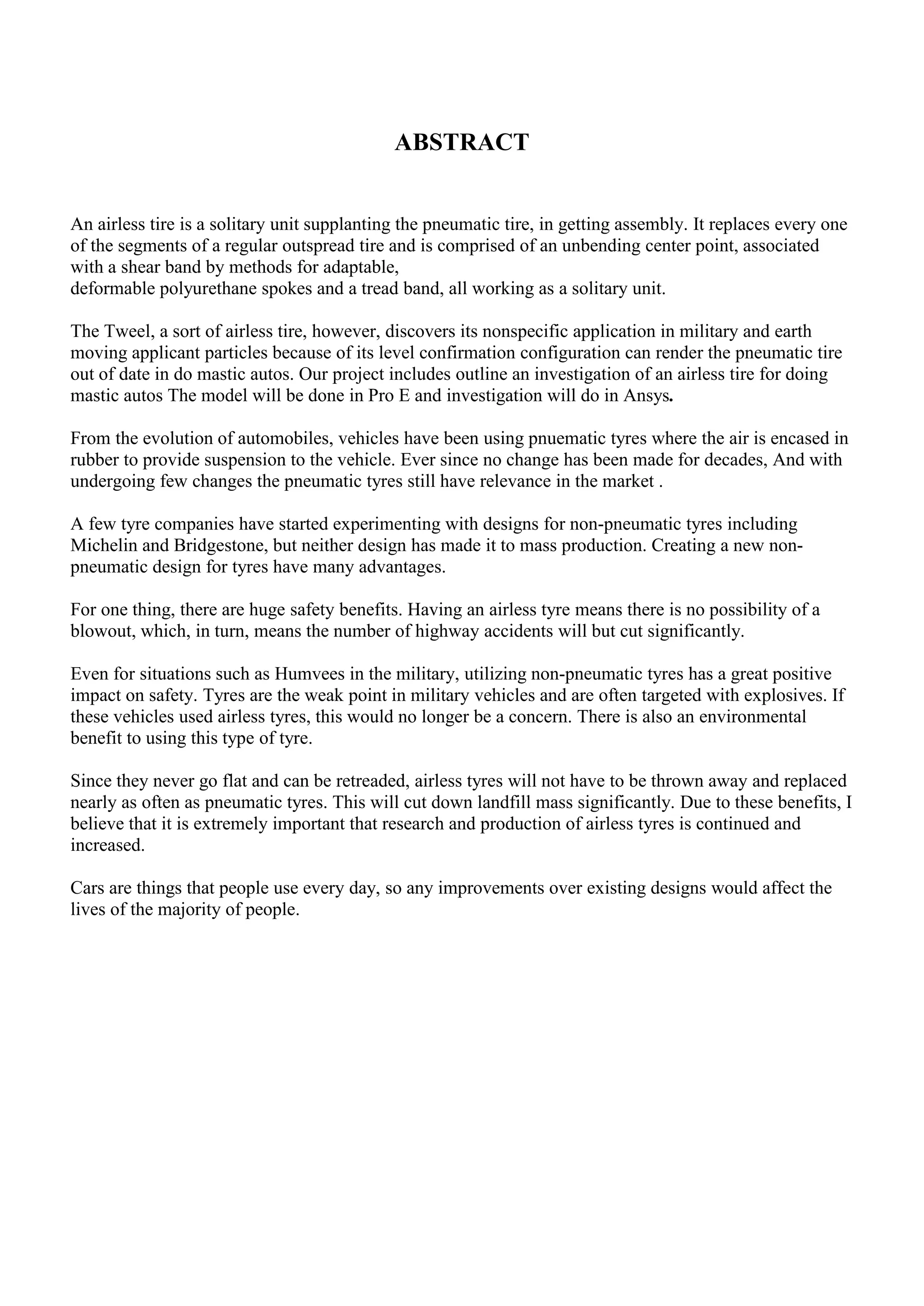
![(1.3) COMPARISION WITH CONVENTIONAL TYRE
ADVANTAGES OF NPT
1. No more air valves.
2. No more air compressors at Petrol Pumps.
3. No more flat tires in the middle of long drives.
4.The Tweel promises performance levels beyond those possible with conventional
Pneumatic technology.
5. Potential benefits of the Tweel include the obvious safety and convenience of never
having flat tyres. Also, the concept has the potential for true performance gains.
6. The Tweel can also withstand a police 'stinger' spike strip, which would force law enforcement to
adapt in order to catch a suspect in a vehicle equipped with Tweels.
7. It provides a comfortable ride and increases vehicle handling
8. Its flexibility provides an increase in surface area of contact thereby increases the grip with the ground.
9. It can take gun fires and spikes without becoming immobile.
DISADVANTAGES OF NPT
1. The non-pneumatic tyre are expensive as compared to pneumatic tyres.
2. The replacement of any component in the non-pneumatic tyre is impossible i.e. Every time the tyre is
worn-out we have to replace the whole assembly.
3. It can withstand police spikes which may make it difficult for law enforcement.
4. Lack of adjustability is one disadvantage of non-pneumatic tyres if once manufactured cannot be
altered or adjusted.
Potential benefits of the Tweel include not only the obvious safety and convenience of never having flat
tires, but also, in automotive applications, the Tweel airless tire has the potential to be able to brake
better – a significant performance compromise that is inherent to pneumatic tires.
Unlike a pneumatic tire, a Tweel can be designed to have high lateral stiffness while simultaneously
having low vertical stiffness. This can be achieved because, in the design elements of a Tweel, the
vertical and lateral stiffness are not inseparably linked and can thus be optimized independently.
Because there is no air bladder under the tread, tread patterns can, if desired, even incorporate water
evacuation through holes in the design thus eliminating or significantly reducing hydroplaning. Michelin
expects the tread to last two to three times as long as a conventional tire. Because the tread rubber
around the outer circumference is replaceable when worn (as opposed to disposing of a whole worn tire),
the potential environmental impact of a Tweel airless tire can be less than that of a conventional
pneumatic tire.
Tweel is useful for: "vehicles that don't have suspensions like lawn mowers – those low speed specialty
vehicles that don't have suspensions. The comfort is quite good and better than inflated tyres" said Terry
K. Gettys, Executive Vice-President, Research and Development, and member of the Group Executive
Committee at French tire company Michelin.[4]
Military testing has indicated that the Tweel deflects mine blasts away from the vehicle better than
standard tires and that the Tweel remains mobile even with several spokes damaged or missing.](https://image.slidesharecdn.com/monishseminarreport-201212070458/75/Non-Pnuematic-Airless-tyres-seminar-report-11-2048.jpg)


![(3.3) FINITE ELEMENT METHOD USED FOR ANALYSIS
The finite element method (FEM) is the most widely used method for solving problems of engineering
and mathematical models. Typical problem areas of interest include the traditional fields of structural
analysis, heat transfer, fluid flow, mass transport, and electromagnetic potential.
The FEM is a particular numerical method for solving partial differential equations in two or three
space variables (i.e., some boundary value problems). To solve a problem, the FEM subdivides a large
system into smaller, simpler parts that are called finite elements. This is achieved by a particular space
discretization in the space dimensions, which is implemented by the construction of a mesh of the object:
the numerical domain for the solution, which has a finite number of points.
The finite element method formulation of a boundary value problem finally results in a system of
algebraic equations. The method approximates the unknown function over the domain.[1] The simple
equations that model these finite elements are then assembled into a larger system of equations that
models the entire problem.
The FEM then uses variational methods from the calculus of variations to approximate a solution by
minimizing an associated error function.
Studying or analyzing a phenomenon with FEM is often referred to as finite element analysis (FEA).
Figure 3.6 Figure 3.7](https://image.slidesharecdn.com/monishseminarreport-201212070458/75/Non-Pnuematic-Airless-tyres-seminar-report-21-2048.jpg)


![Airless-Tyres-Seminar-Reports.pptx_20231119_223223_0000[1].pptx](https://cdn.slidesharecdn.com/ss_thumbnails/airless-tyres-seminar-reports-240326093510-57310ba4-thumbnail.jpg?width=640&height=640&fit=bounds)


