Downloaded 392 times

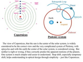
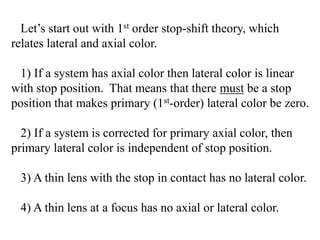
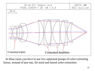

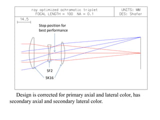
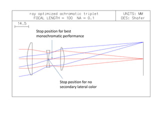
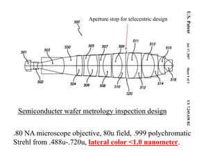
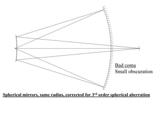


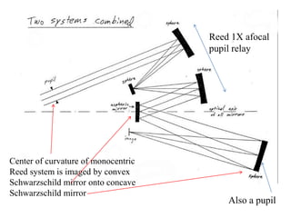

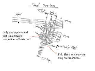
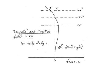
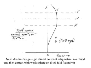


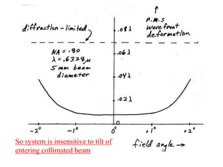


The document explores the application of stop-shift theory in optical design, highlighting its capacity to simplify design processes and enhance understanding of optical aberrations without extensive computations. It discusses various examples, including the Copernican system analogy, designs for semiconductor metrology, and advanced lens configurations, demonstrating how stop position adjustments can optimize correction of axial and lateral colors. Ultimately, it asserts that temporary stop shifts are valuable tools for achieving effective optical systems while maintaining the desired final aperture stop location.


