Download to read offline

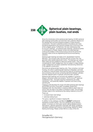
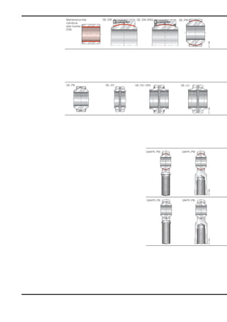
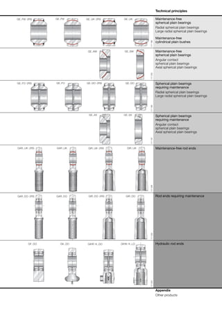
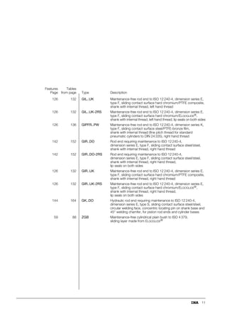
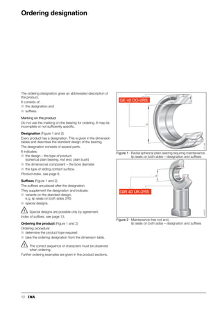
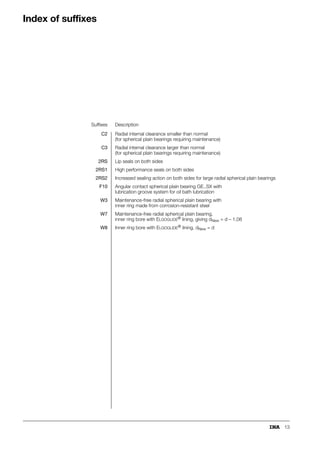
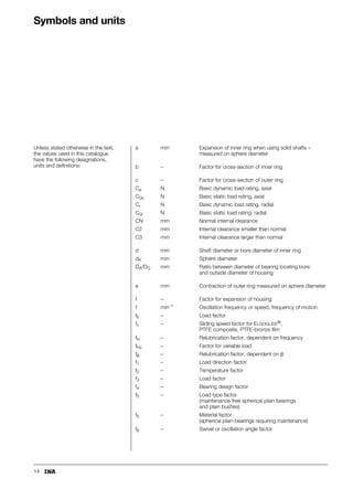

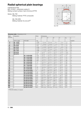
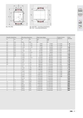
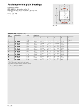
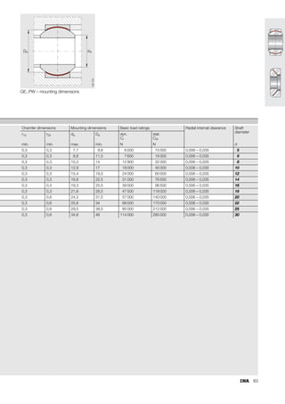
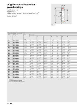
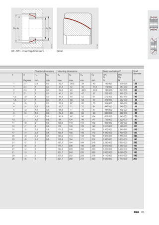
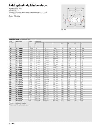
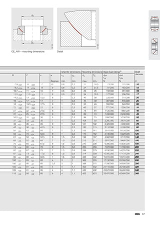
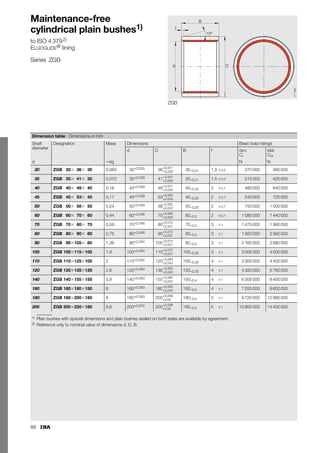

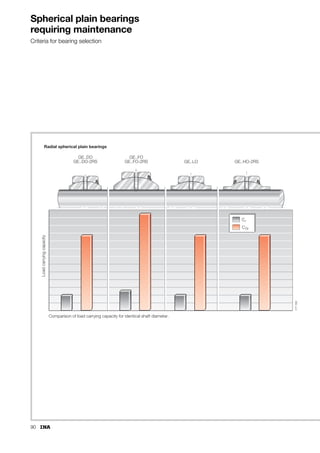
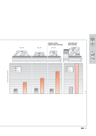
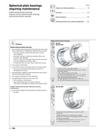
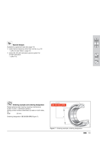
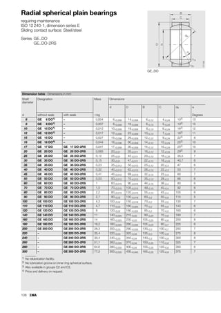
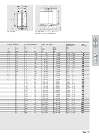
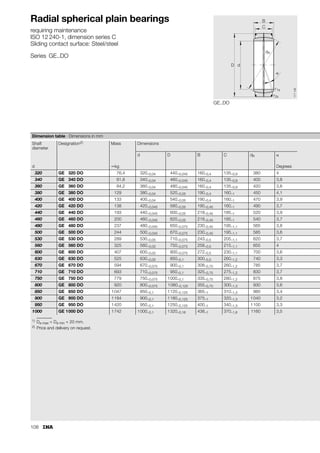


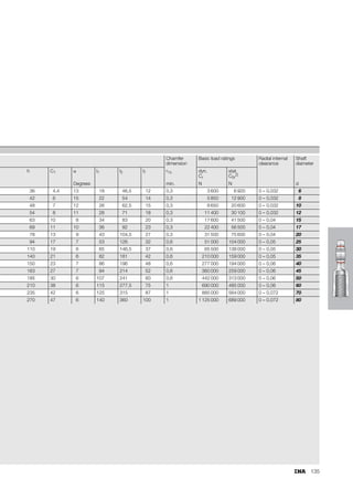
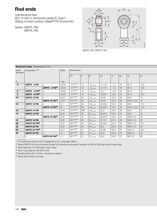

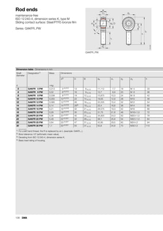

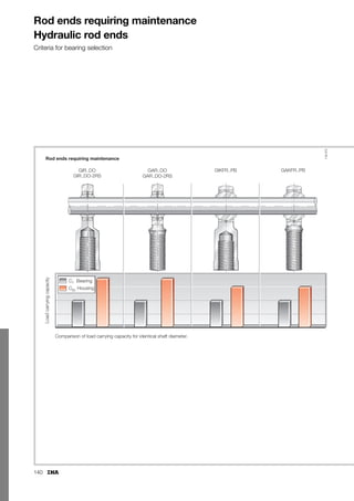

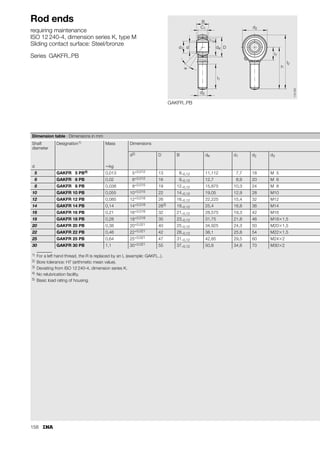
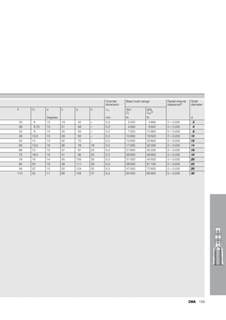
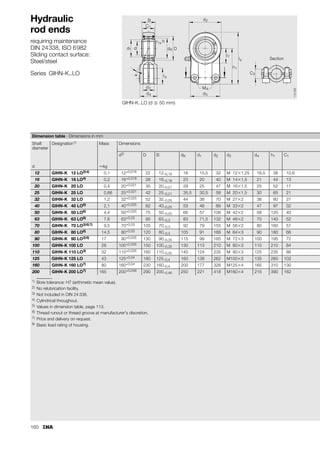
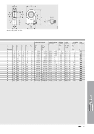
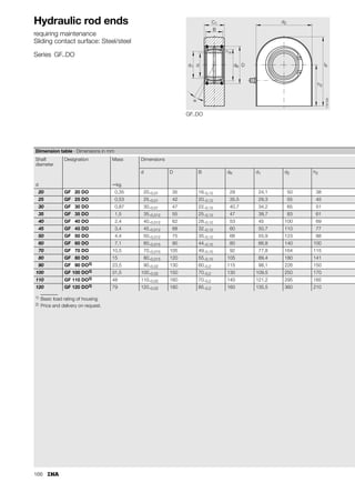
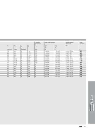


This document provides a catalogue of spherical plain bearings, plain bushes, and rod ends produced by ELGES. It describes the product range, which includes maintenance-free and maintenance-requiring spherical plain bearings, cylindrical plain bushes, and rod ends. The catalogue has been completely revised from the previous edition. Key changes include increased load ratings and extended sliding travel for the maintenance-free ELGOGLIDE® bearings.