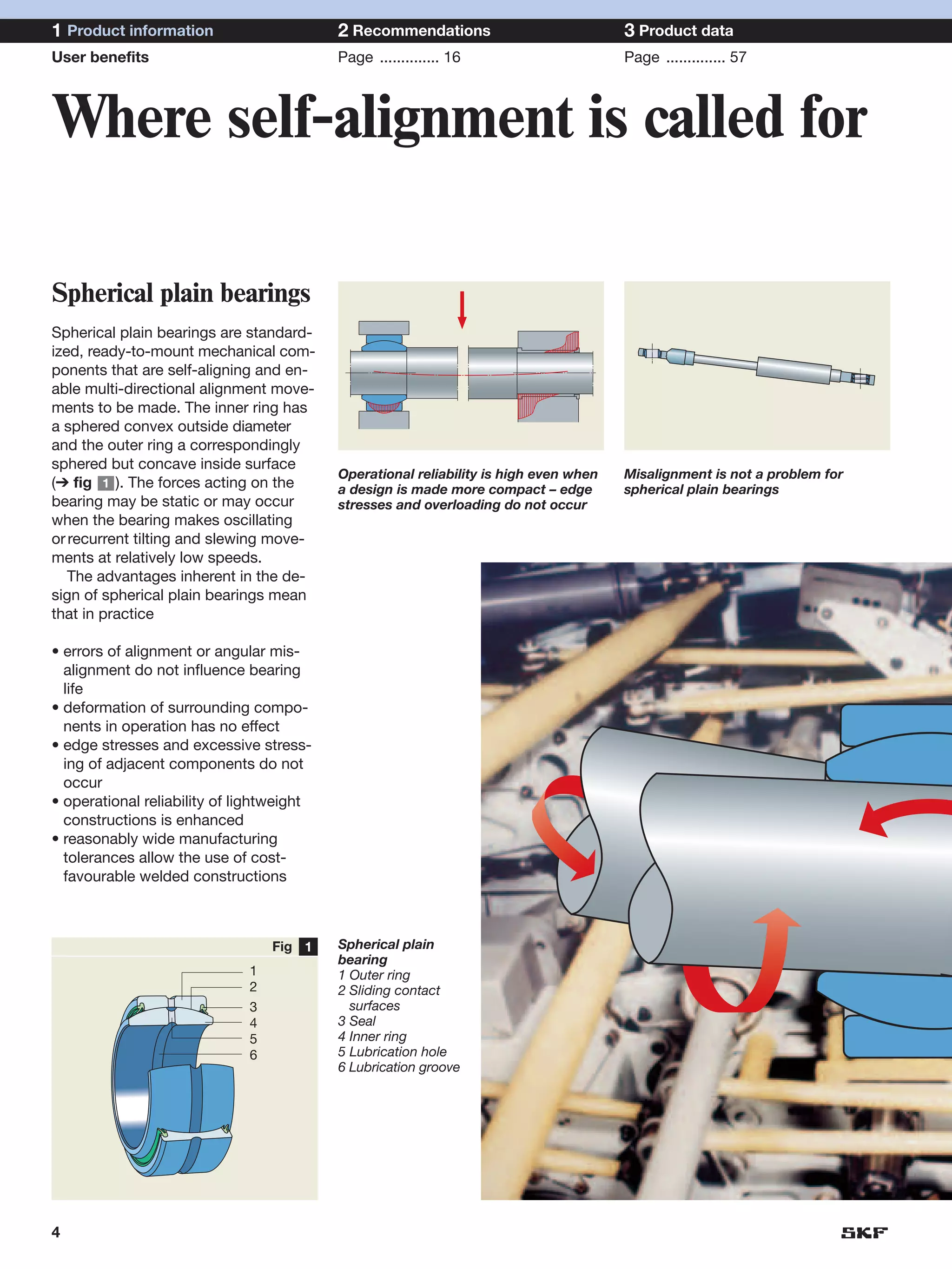
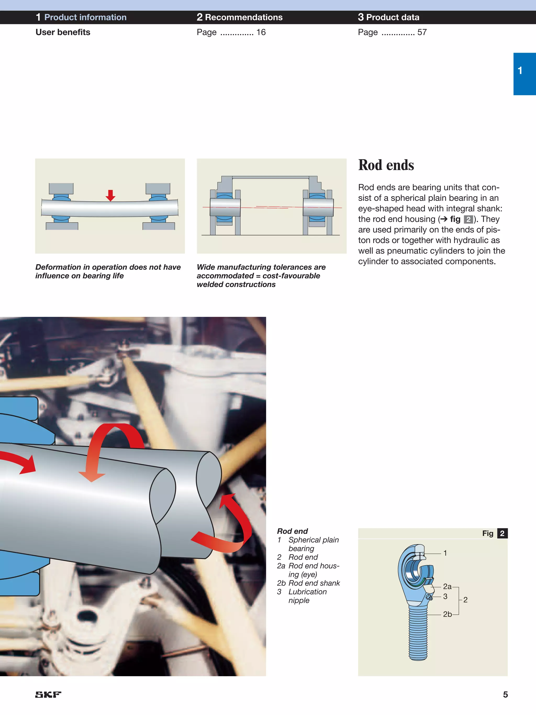
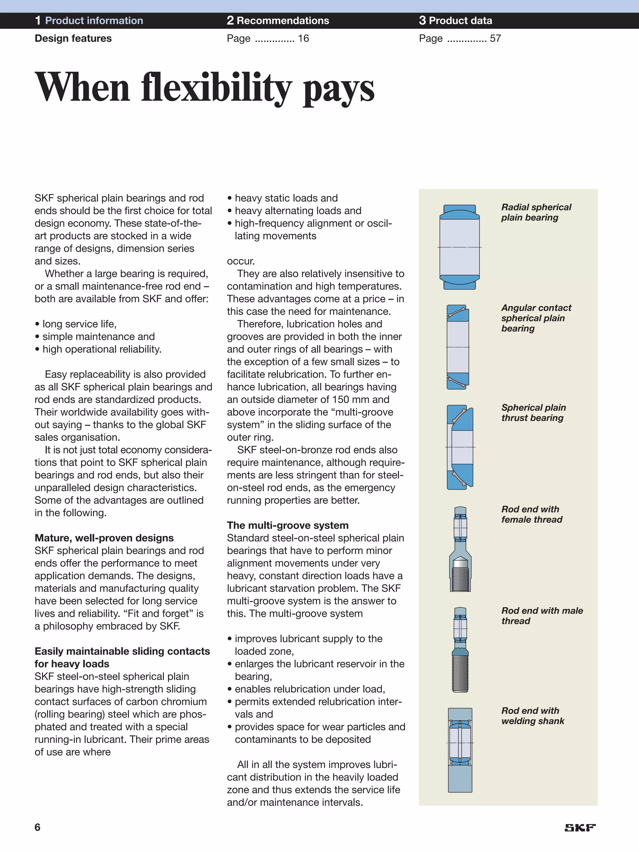
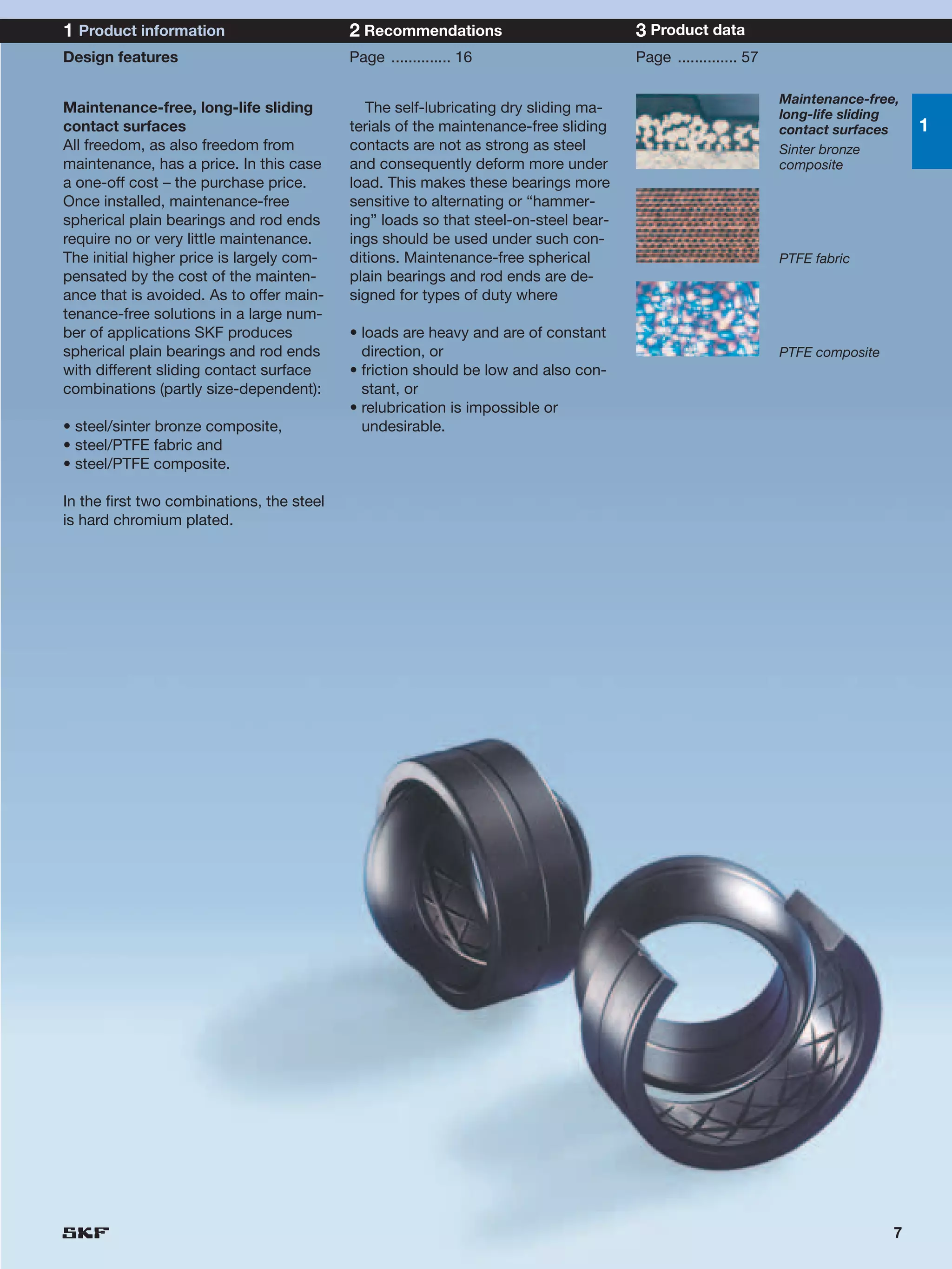
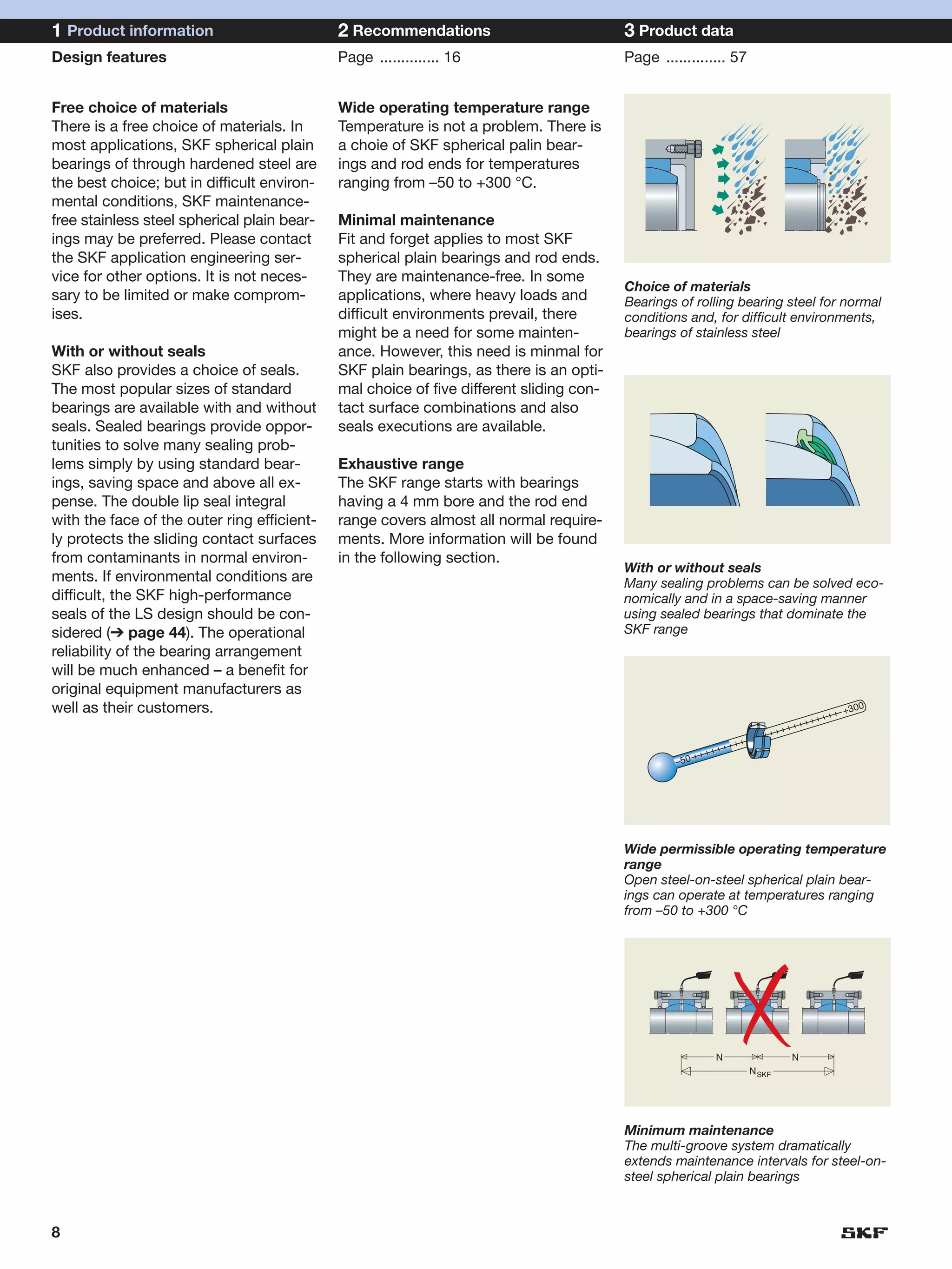
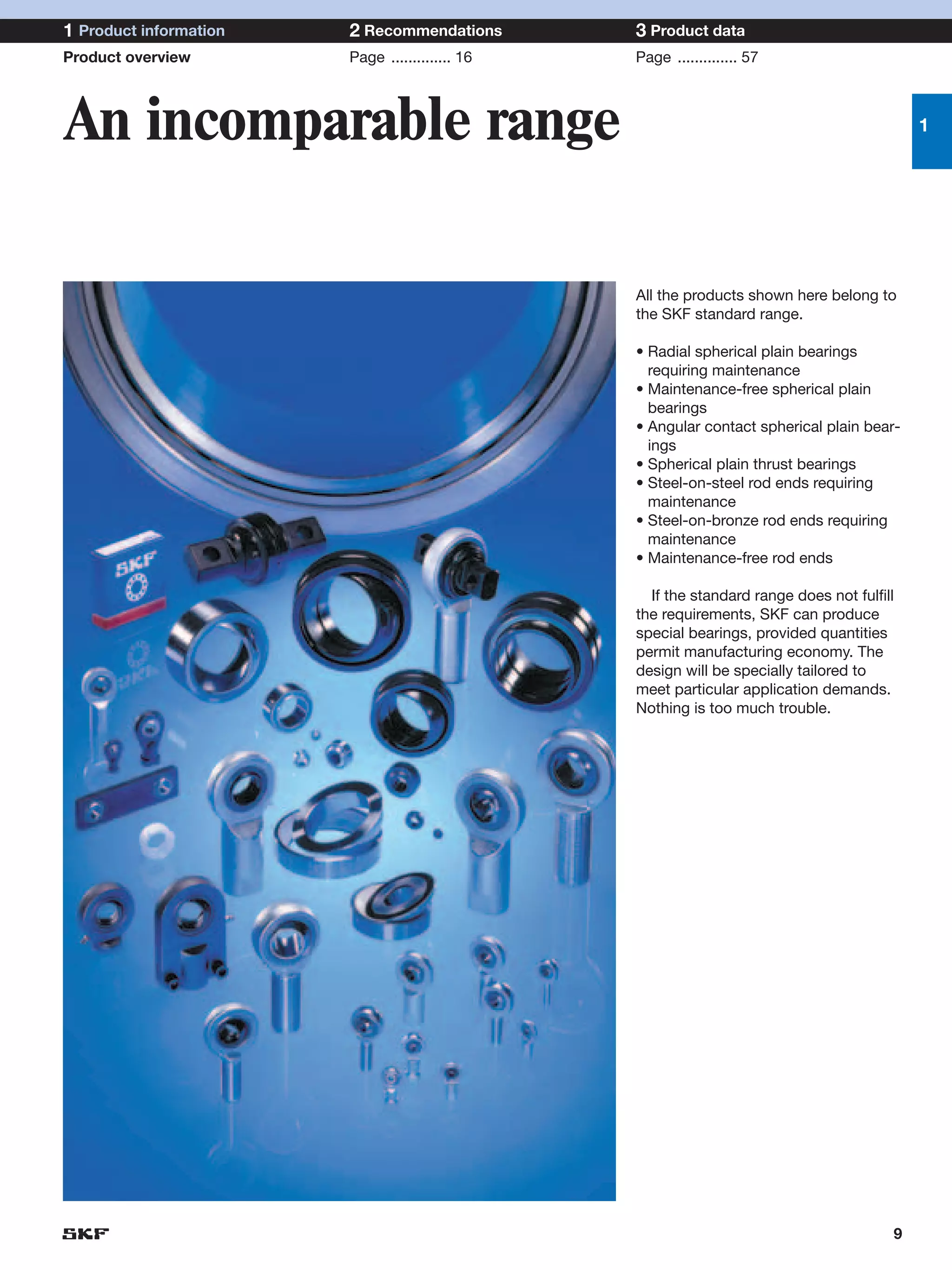
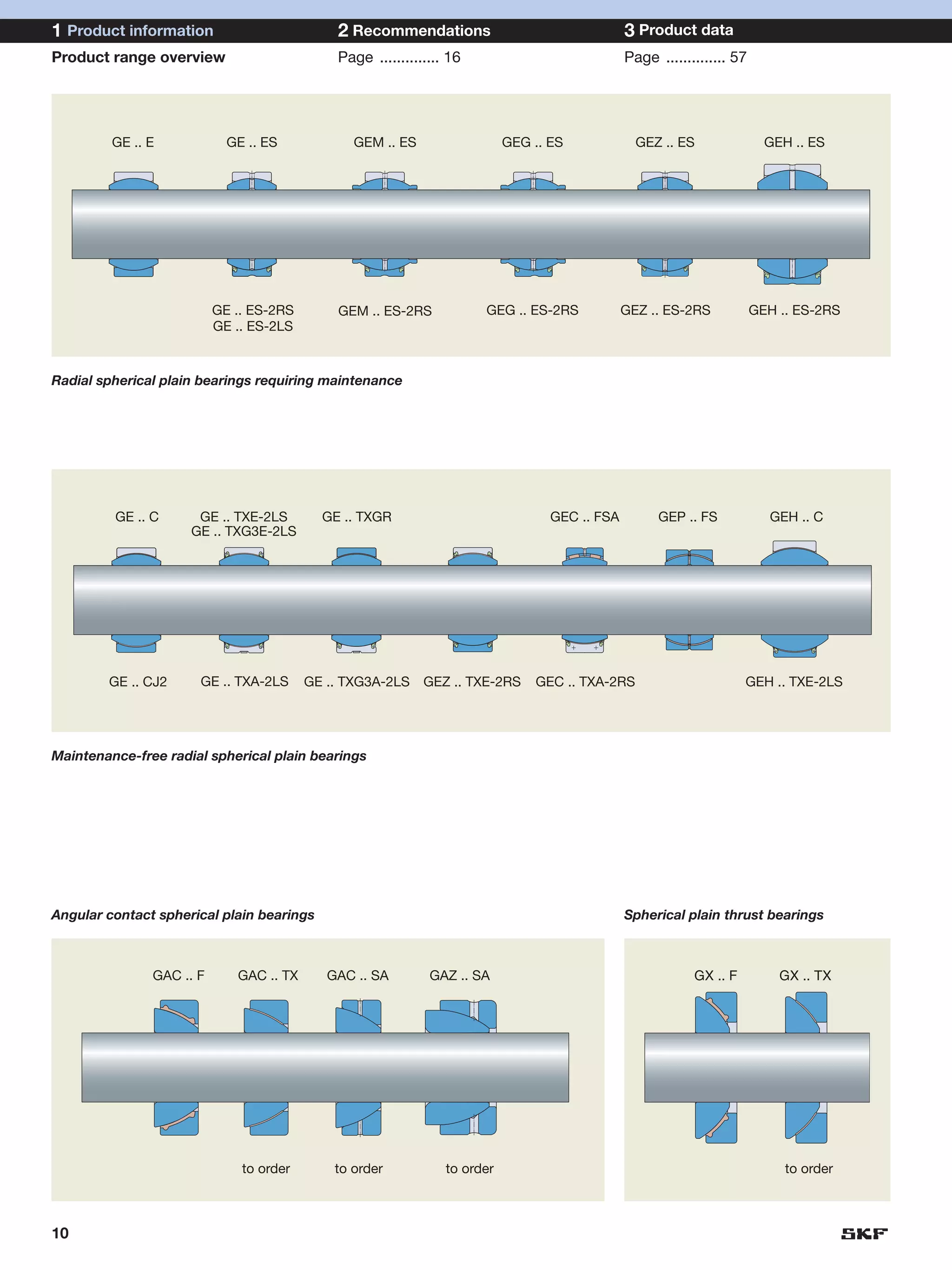
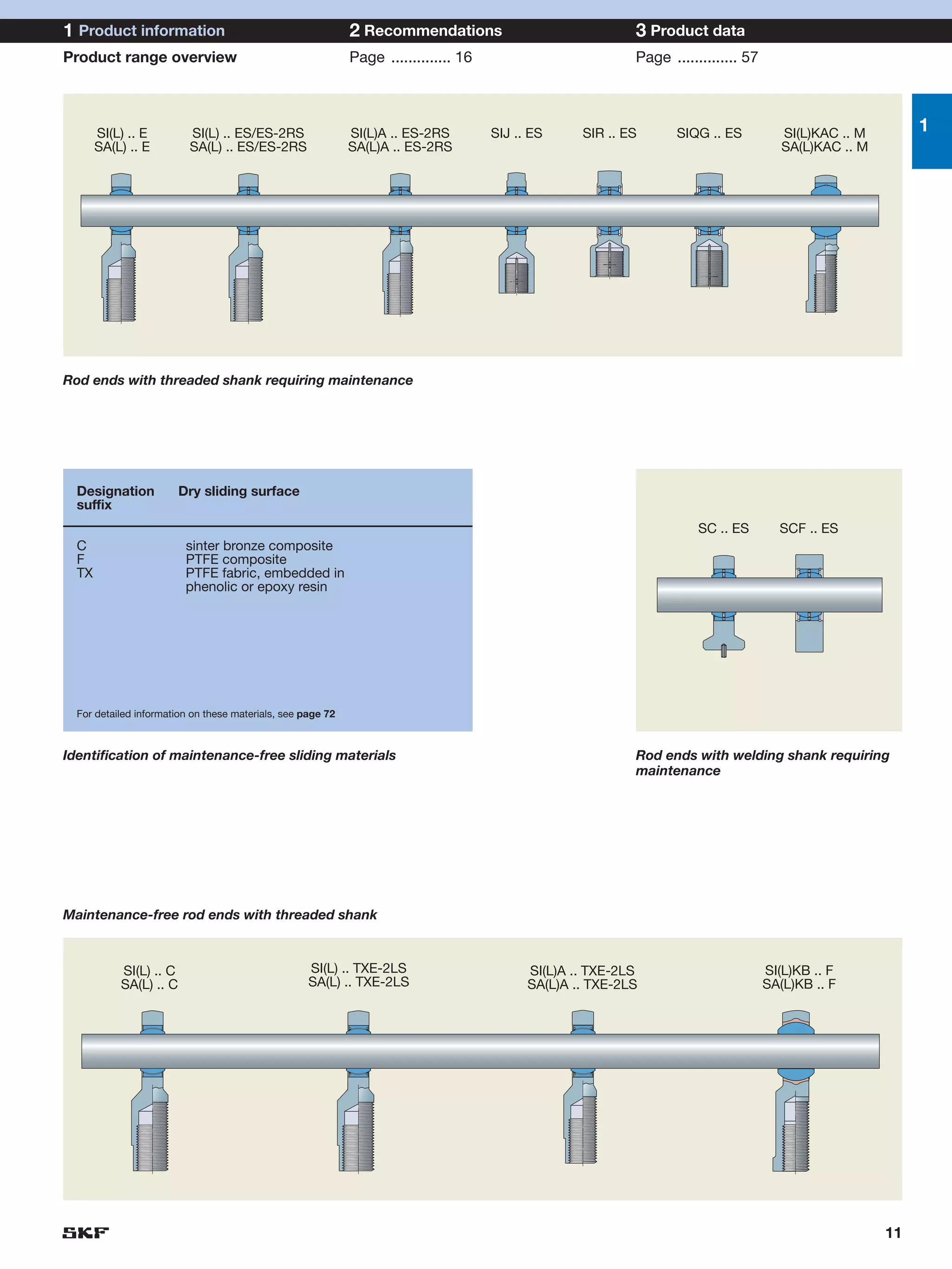
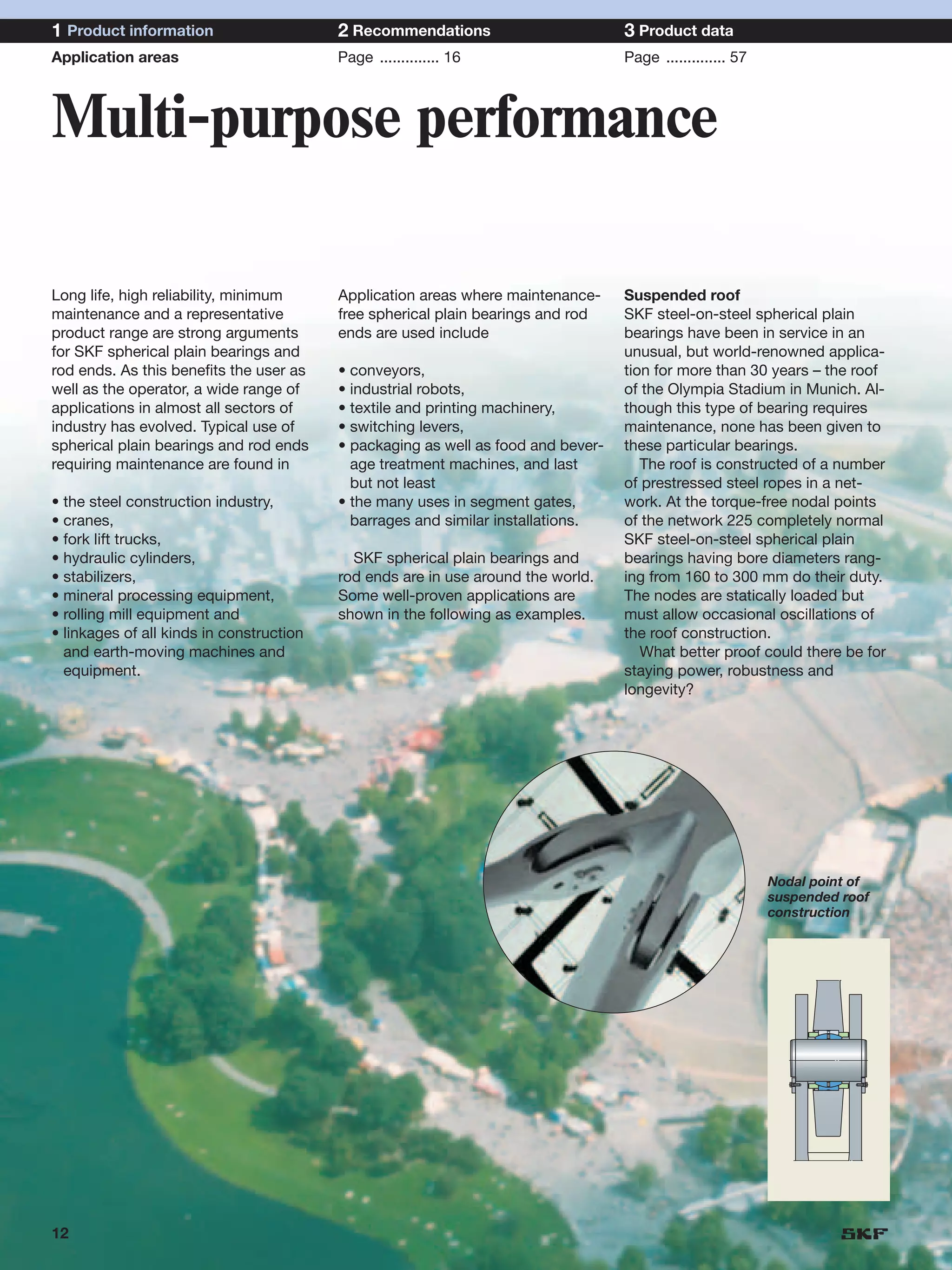
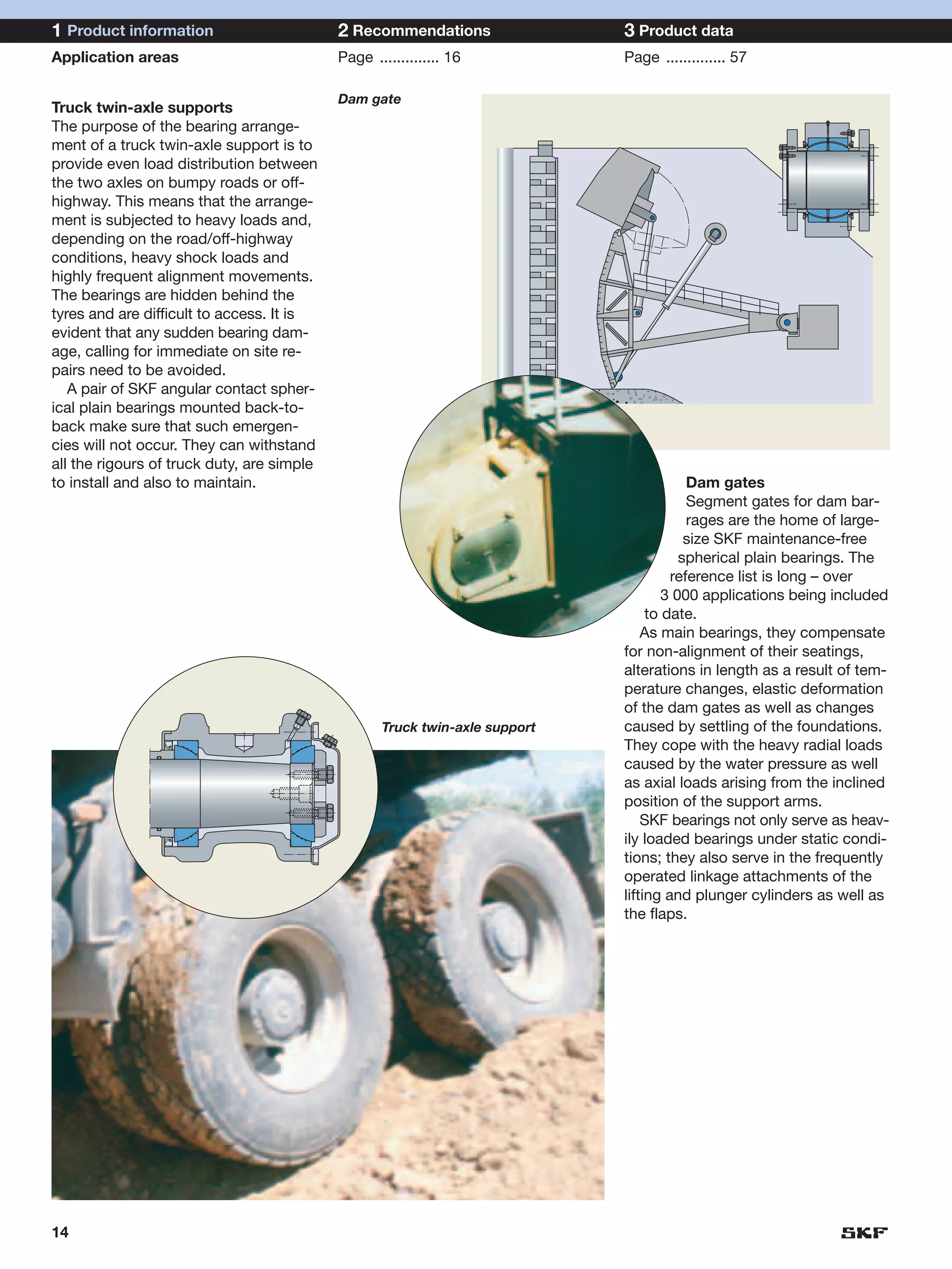
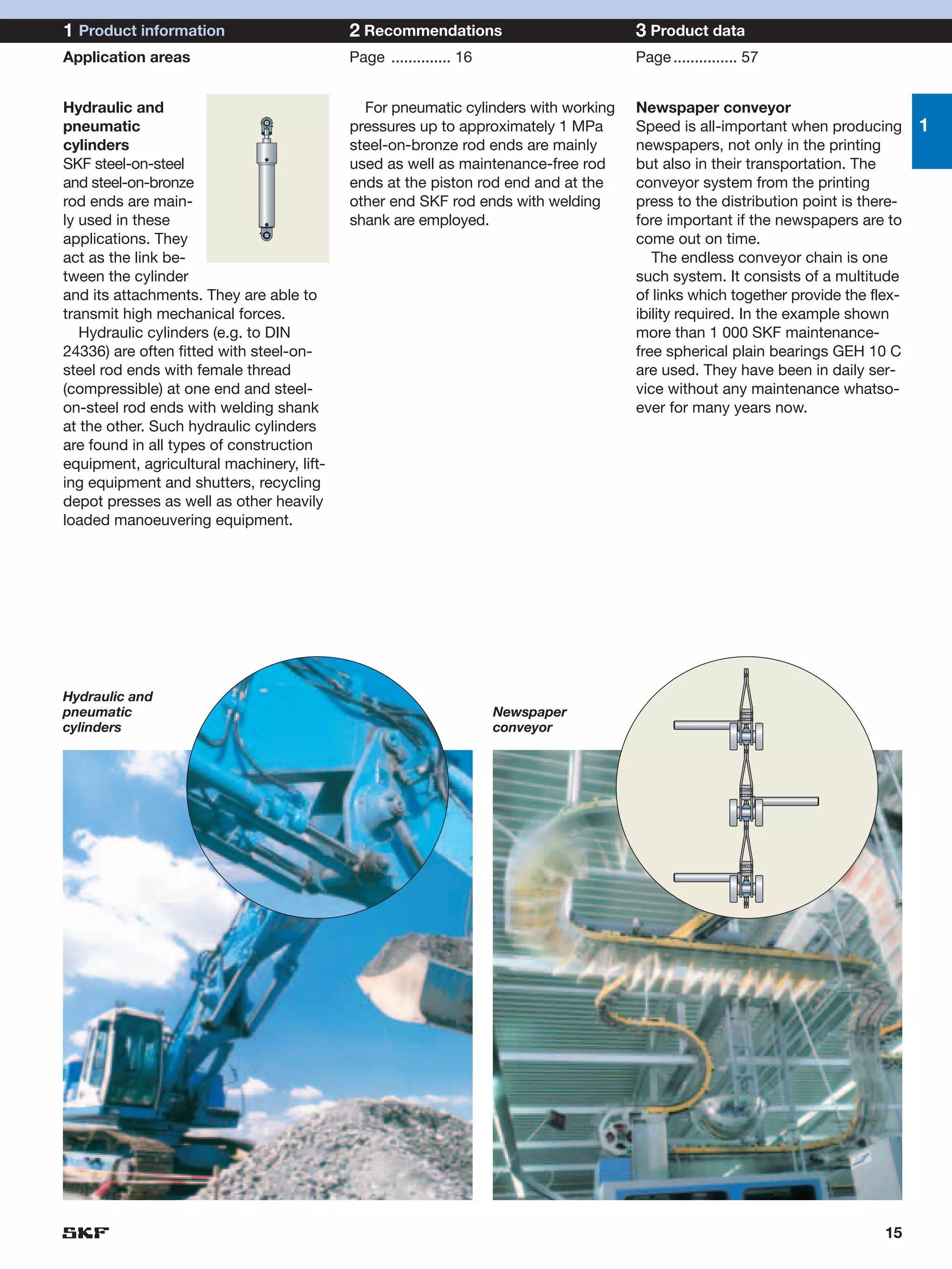
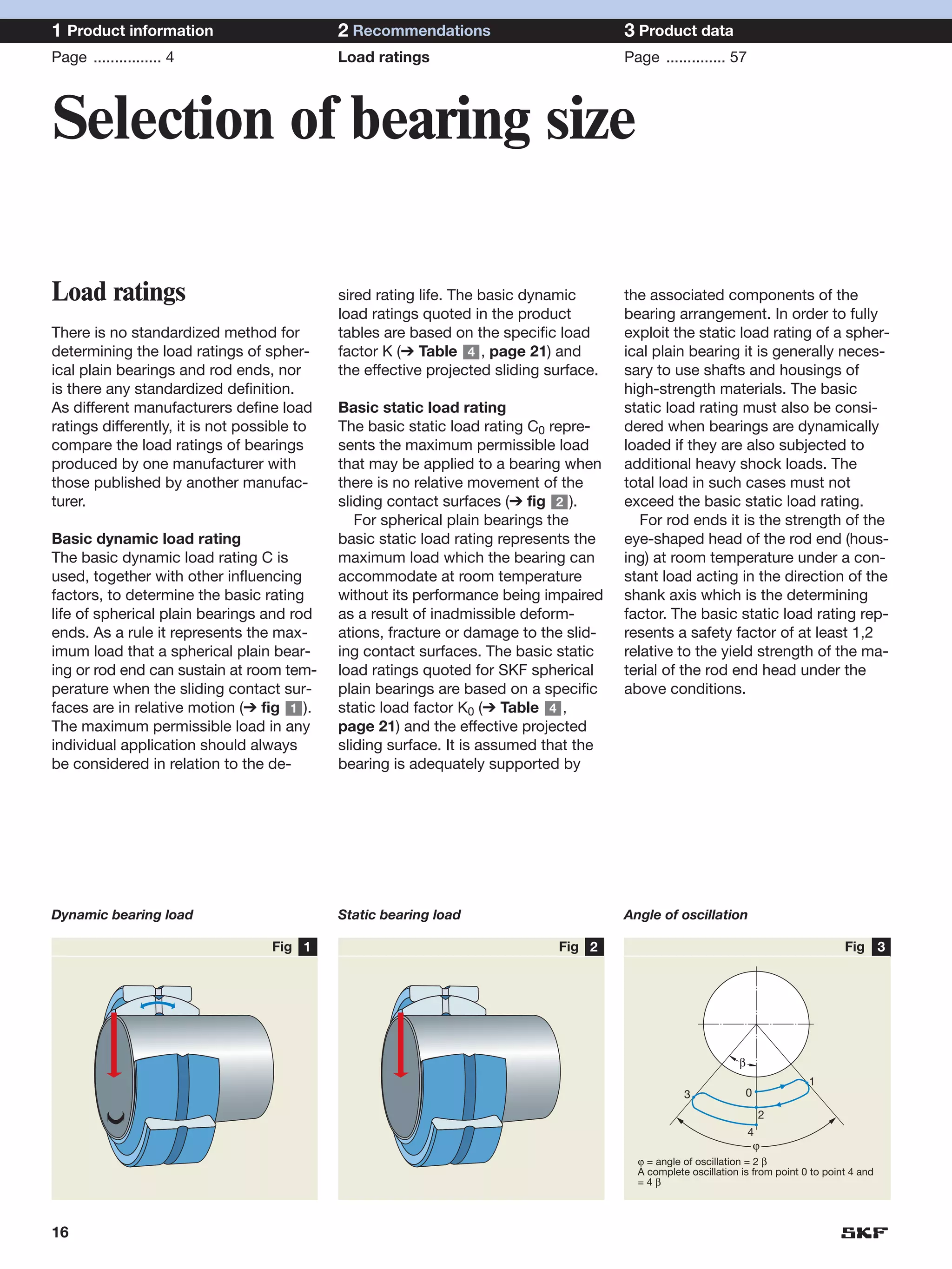
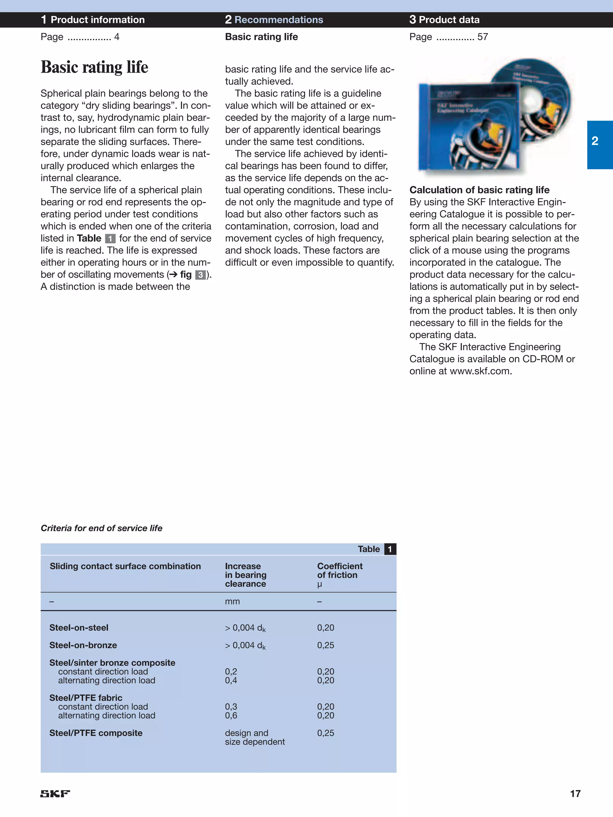
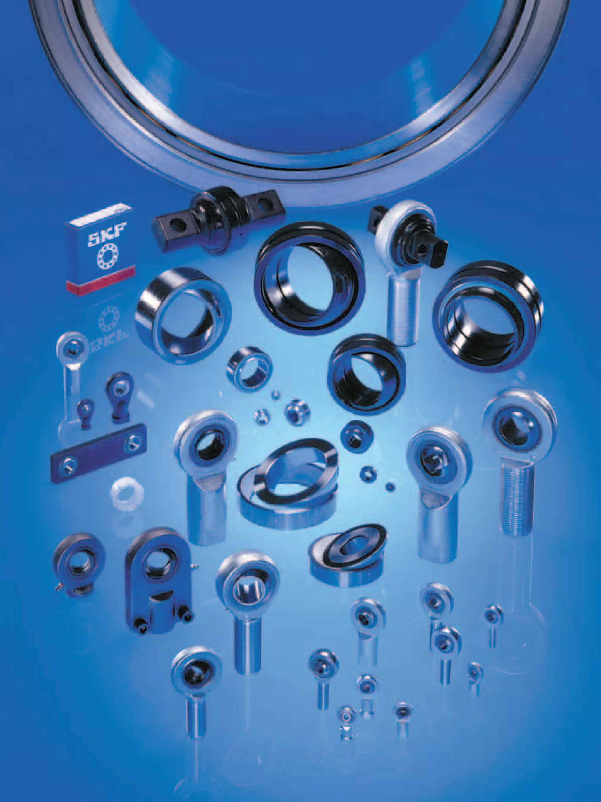
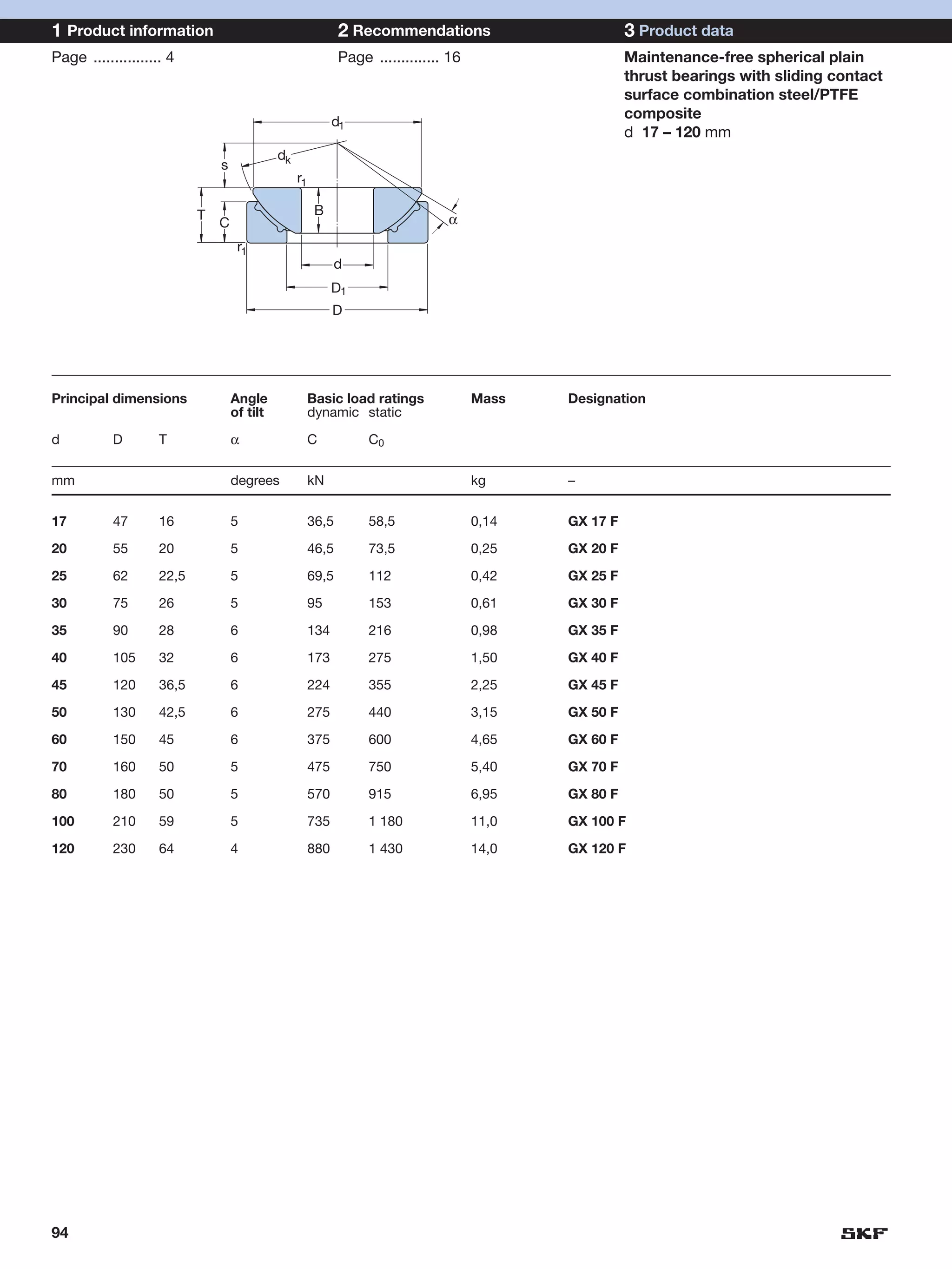
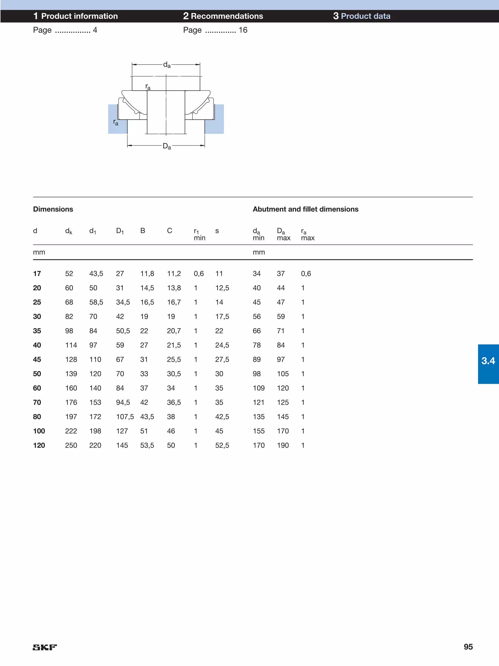
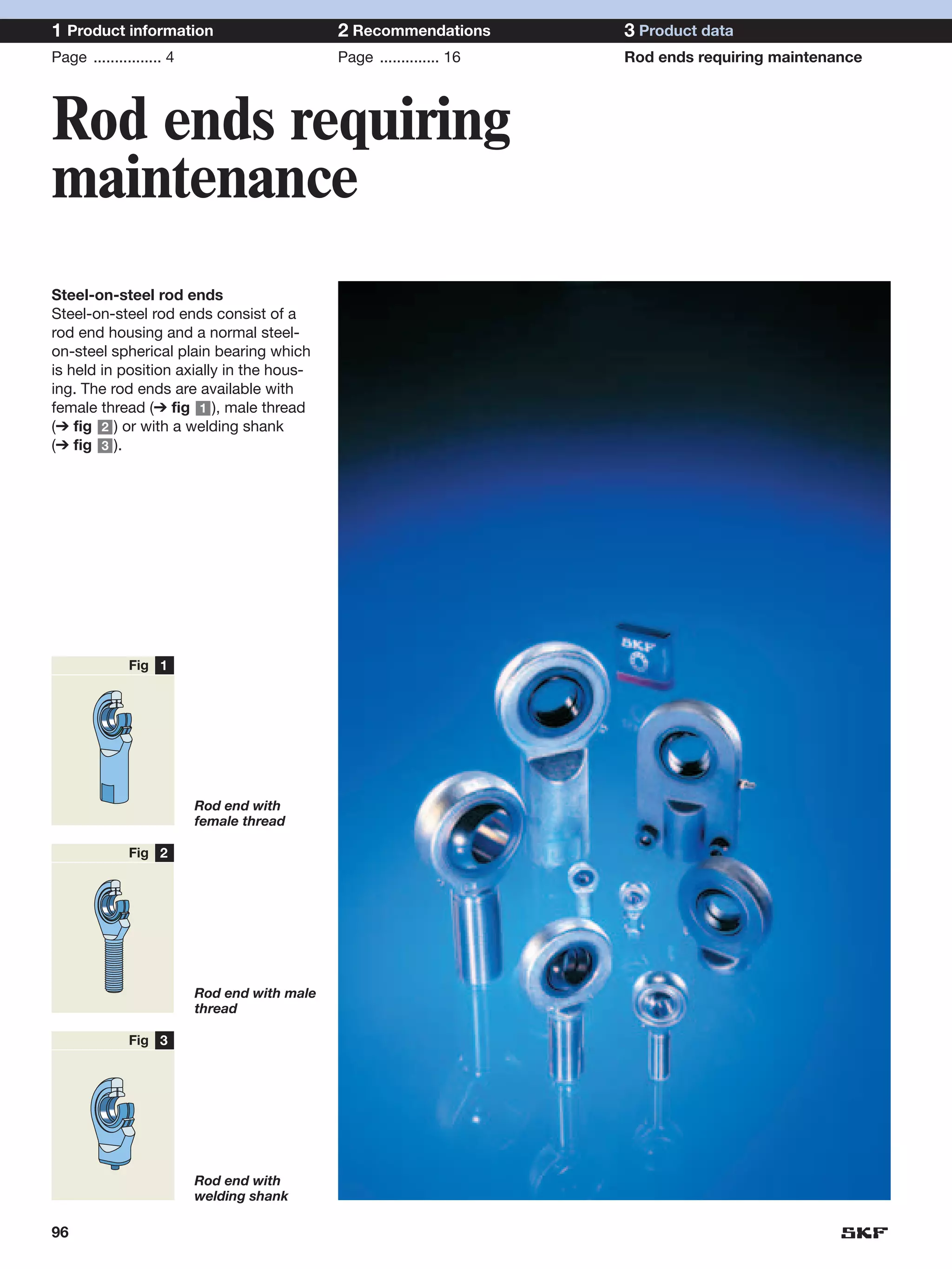
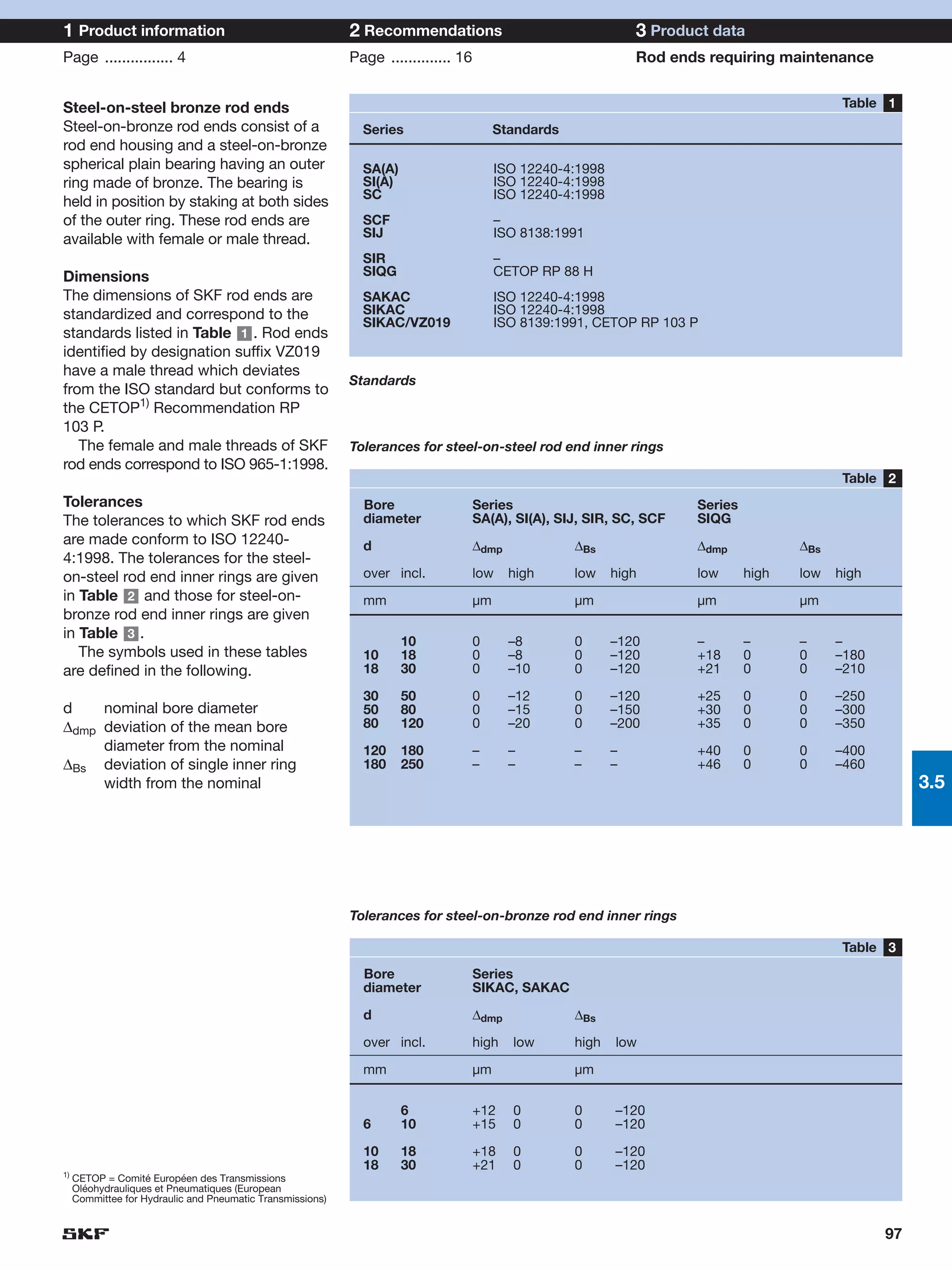
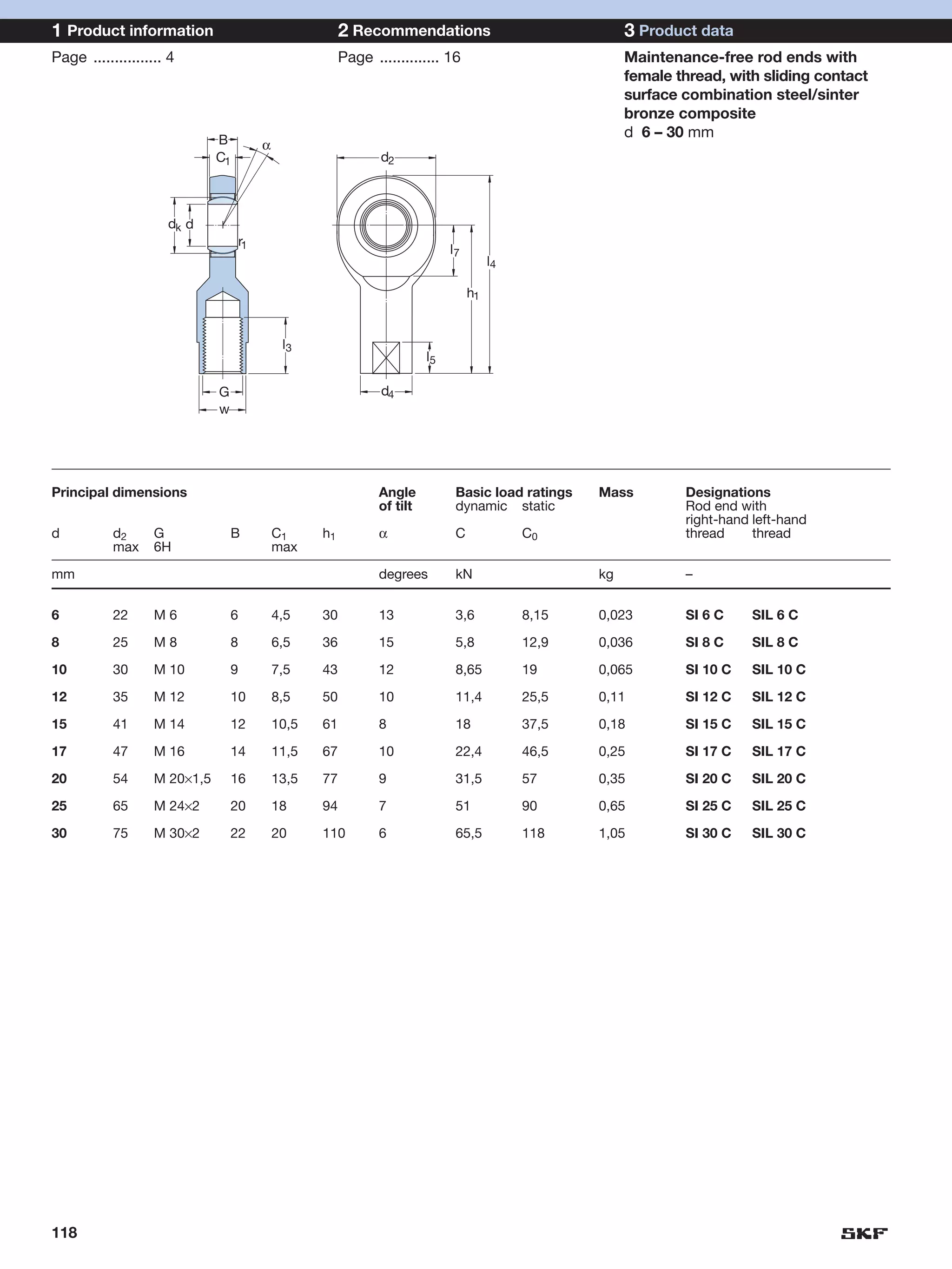
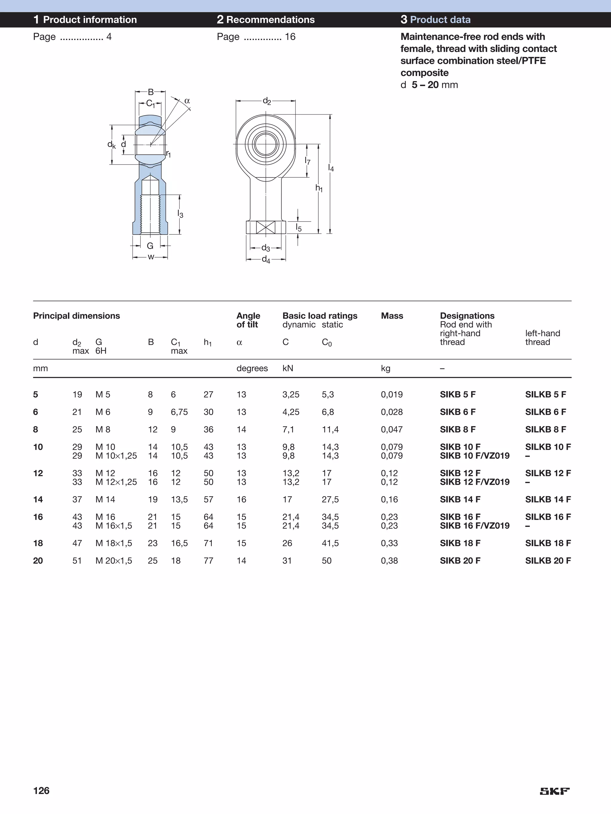
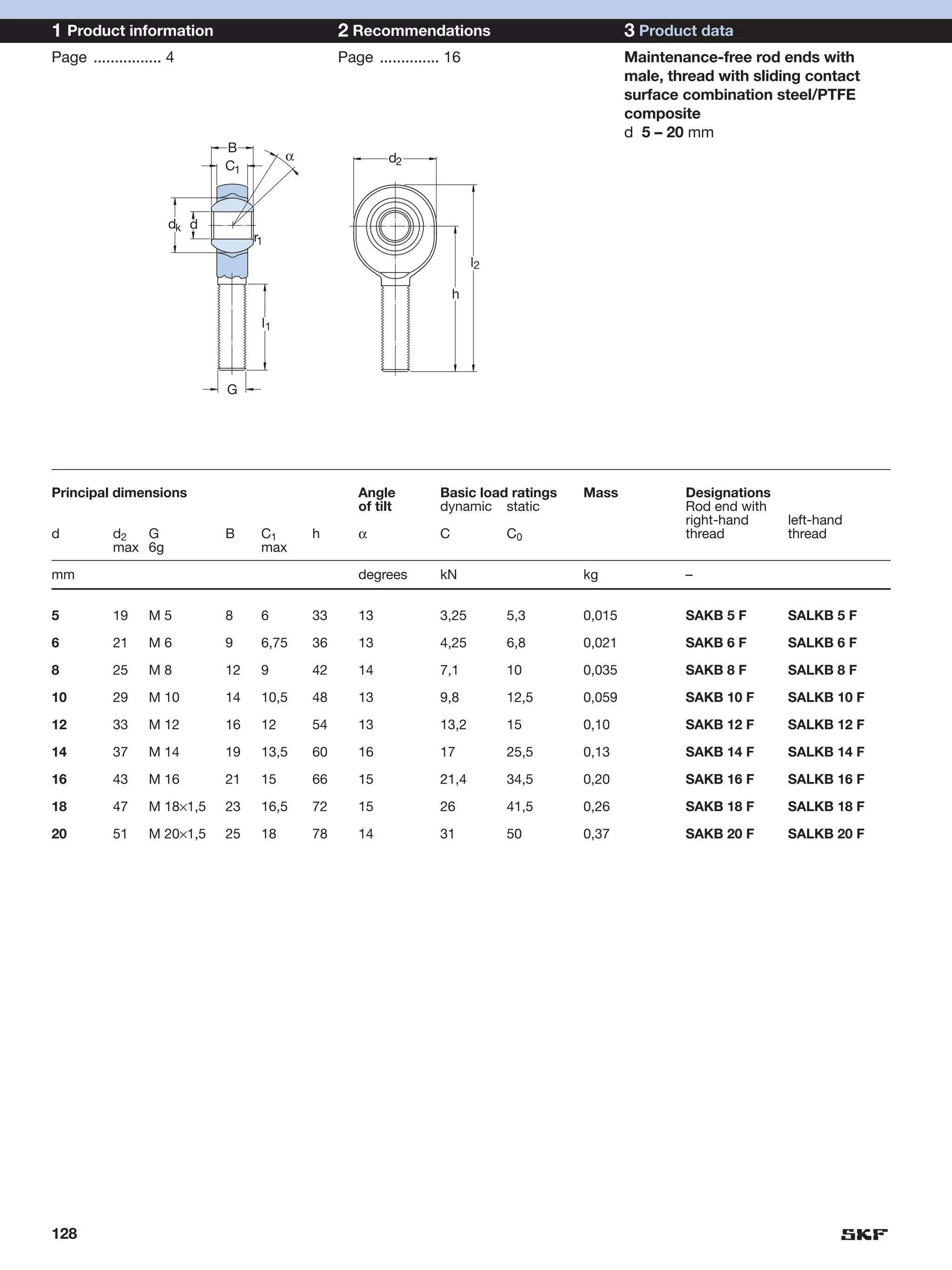
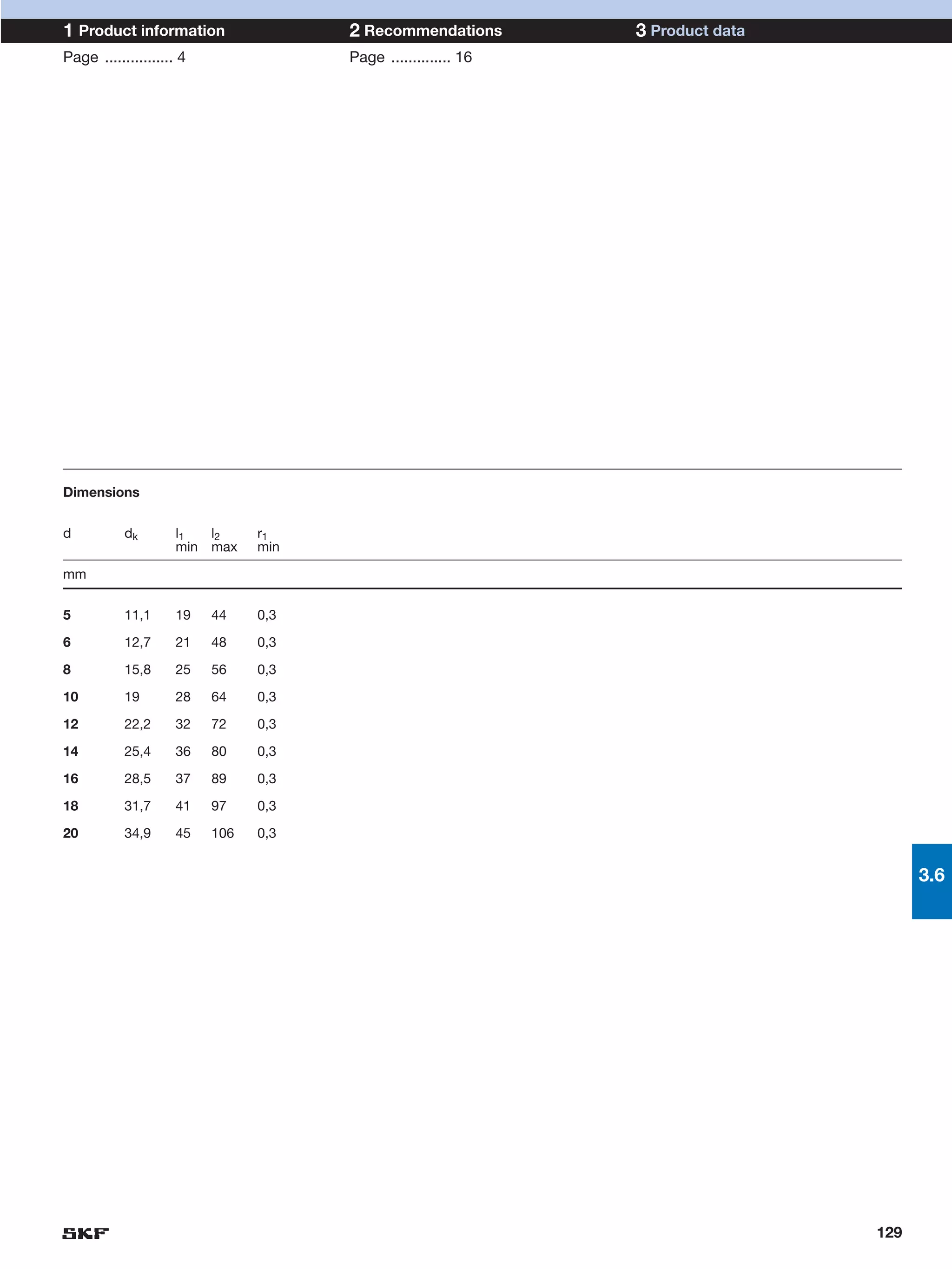
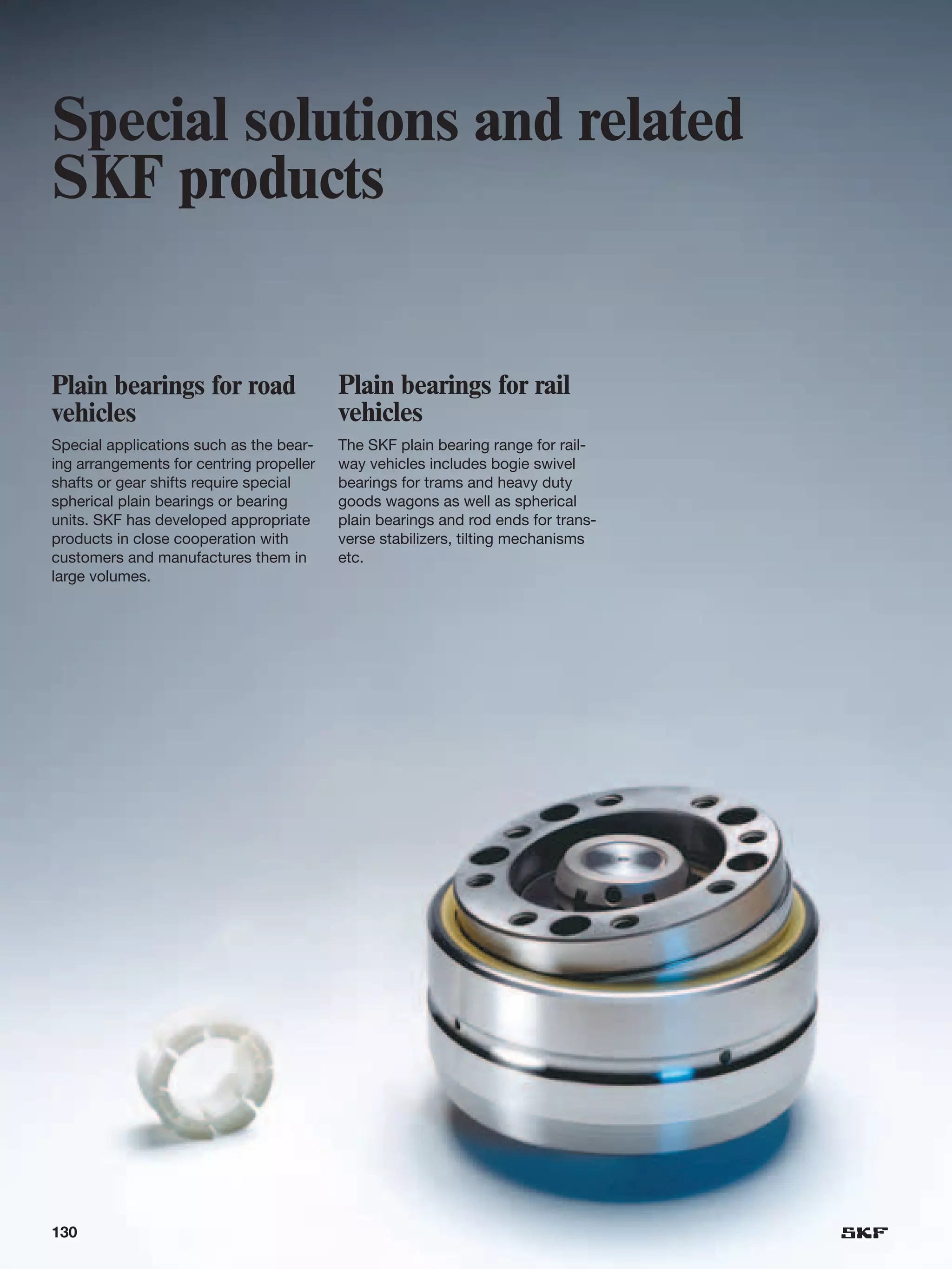
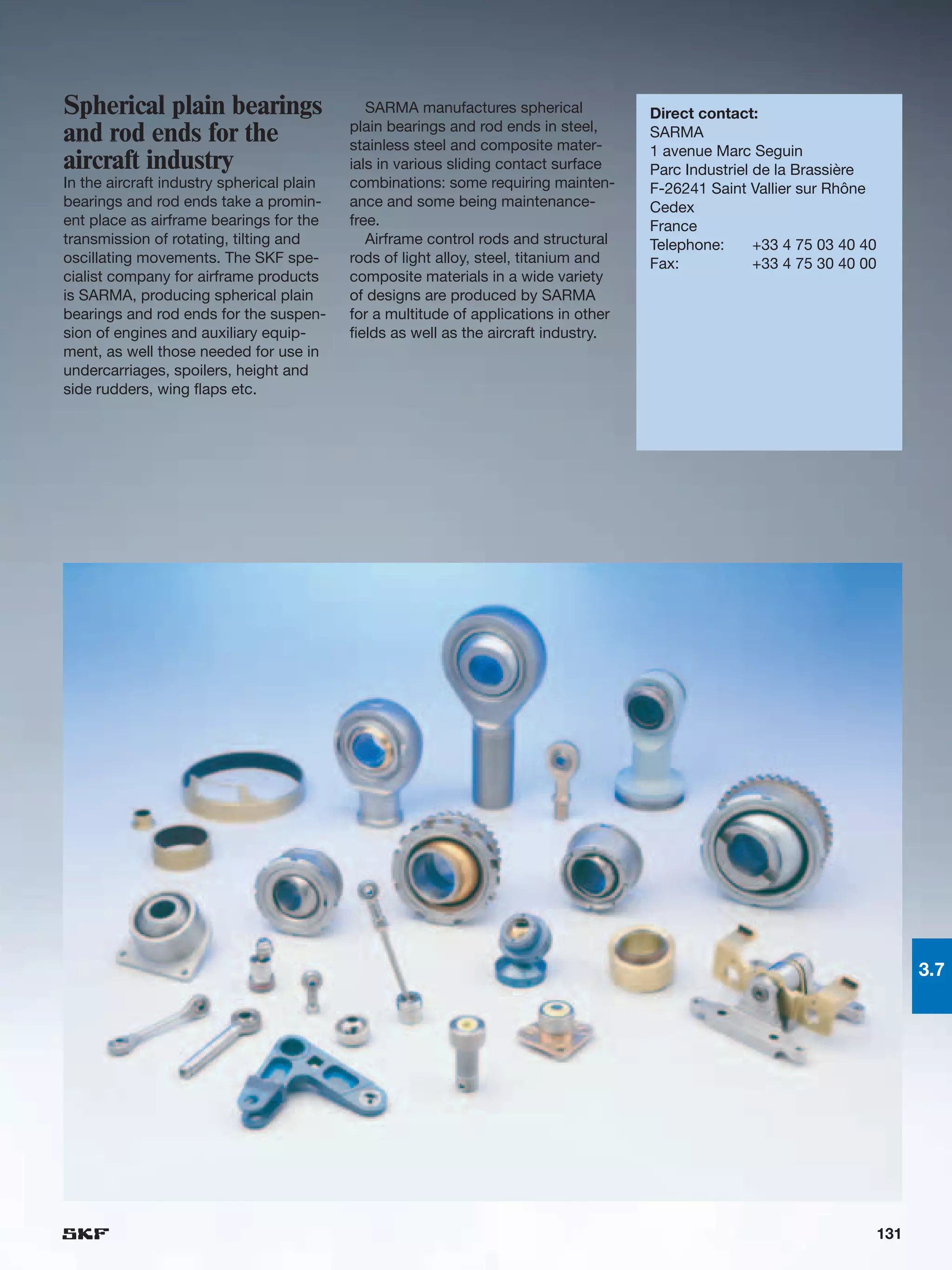
SKF spherical plain bearings
and rod ends
Contents

The SKF brand now stands for more than ever before,            1   Product information ................................................ 4
and means more to you as a valued customer.
                                                             Where self-alignment is called for ................................ 4
                                                             When flexibility pays ...................................................... 6
While SKF maintains its leadership as the hallmark of
                                                             An incomparable range ................................................. 9
quality bearings throughout the world, new dimensions
                                                             Multi-purpose performance .......................................... 12
in technical advances, product support and services
have evolved SKF into a truly solutions-oriented supplier,
creating greater value for customers.
                                                               2   Recommendations .................................................. 16
                                                             Selection of bearing size ............................................... 16
These solutions encompass ways to bring greater                 Load ratings ................................................................. 16
productivity to customers, not only with breakthrough           Basic rating life ............................................................ 17
application-specific products, but also through leading-        Load ............................................................................. 18
edge design simulation tools and consultancy services,             Equivalent dynamic bearing load ............................ 18
plant asset efficiency maintenance programs, and the               Equivalent static bearing load ................................. 20
industry’s most advanced supply management                         Permissible loads for rod ends................................ 20
techniques.                                                     Requisite bearing size.................................................. 21
                                                                   Specific bearing load............................................... 21
The SKF brand still stands for the very best in rolling            Mean sliding velocity ............................................... 21
bearings, but it now stands for much more.                      Basic rating life ............................................................ 24
                                                                   Sliding contact surface combinations
SKF – The knowledge engineering company                            requiring maintenance: steel-on-steel and
                                                                   steel-on-bronze ....................................................... 24
                                                                   Maintenance-free sliding contact surface
                                                                   combination steel/sinter bronze composite ............ 26
                                                                   Maintenance-free sliding contact surface
                                                                   combination steel/PTFE fabric ................................ 27
                                                                   Maintenance-free sliding contact surface
                                                                   combination steel/PTFE composite ........................ 29
                                                                   Variable load and sliding velocity ............................ 30
                                                                Calculation examples................................................... 30
                                                             Friction ............................................................................ 35
                                                             Application of bearings.................................................. 36
                                                                Radial location of bearings .......................................... 36
                                                                Axial location of bearings............................................. 40
                                                                Sealing ......................................................................... 43
                                                                Designing the bearing arrangement for easy
                                                                mounting and dismounting .......................................... 46
                                                             Lubrication ...................................................................... 48
                                                                Spherical plain bearings requiring maintenance.......... 48
                                                                Maintenance-free spherical plain bearings.................. 48
                                                                Rod ends requiring maintenance................................. 50
                                                                Maintenance-free rod ends.......................................... 50
                                                             Maintenance ................................................................... 51
                                                             Mounting ......................................................................... 52
                                                                Spherical plain bearings ............................................. 52
                                                                Rod ends ..................................................................... 54
                                                             Dismounting.................................................................... 55
                                                                Spherical plain bearings ............................................. 55
                                                                Rod ends ..................................................................... 55

2
3   Product data ............................................................ 57
Radial spherical plain bearings
                                                                                        Product information . . . . . . . . . . . . . . . . . . . . . . .         4       1
requiring maintenance .................................................. 58
  General ....................................................................... 58
  Steel-on-steel spherical plain bearings
     with metric dimensions............................................ 62
     with inch dimensions............................................... 66
                                                                                        Recommendations . . . . . . . . . . . . . . . . . . . . . . . .          16       2
     with extended inner ring .......................................... 70
Maintenance-free radial spherical plain bearings ...... 72
  General ....................................................................... 72
  Bearings with sliding contact surface combination
     steel/sinter bronze composite ................................ 76
                                                                                        Product data . . . . . . . . . . . . . . . . . . . . . . . . . . . . .   57       3
     steel/PTFE fabric ..................................................... 78
     steel/PTFE composite ............................................ 82
Angular contact spherical plain bearings .................... 86
                                                                                        Radial spherical plain bearings
  General ........................................................................ 86
  Maintenance-free bearings with sliding contact
                                                                                        requiring maintenance . . . . . . . . . . . . . . . . . . . . .          58       3.1
  surface combination steel/PTFE composite ............... 90
Spherical plain thrust bearings ..................................... 92
  General ........................................................................ 92
                                                                                        Maintenance-free radial spherical
  Maintenance-free bearings with sliding contact
  surface combination steel/PTFE composite ................ 94
                                                                                        plain bearings . . . . . . . . . . . . . . . . . . . . . . . . . . . .   72       3.2
Rod ends requiring maintenance ................................. 96
  General ....................................................................... 96
  Steel-on-steel rod ends
     with female thread ...................................................100
     with female thread for hydraulic cylinders ..............102
                                                                                        Angular contact spherical plain bearings . . . . .                       86       3.3
     with male thread .....................................................104
     with cylindrical section welding shank ....................106
     with rectangular section welding shank .................108
  Steel-on-bronze rod ends
     with female thread ...................................................110
                                                                                        Spherical plain thrust bearings . . . . . . . . . . . . . .              92       3.4
     with male thread .....................................................112
Maintenance-free rod ends ...........................................114
  General ........................................................................114
  Maintenance-free rod ends
     with female thread, steel/sinter bronze composite 118
                                                                                        Rod ends requiring maintenance . . . . . . . . . . . .                   96       3.5
     with male thread, steel/sinter bronze composite ....120
     with female thread, steel/PTFE fabric .....................122
     with male thread, steel/PTFE fabric ........................124
     with female thread, steel/PTFE composite..............126
     with male thread, steel/PTFE composite ................128
                                                                                        Maintenance-free rod ends . . . . . . . . . . . . . . . . . 114                   3.6
Special solutions and related products........................130
  Plain bearings for road vehicles ..................................130
  Plain bearings for rail vehicles ....................................130
  Spherical plain bearings and rod ends for
  airframe applications ..................................................131
                                                                                        Special solutions and related products . . . . . . . 130                          3.7
  Dry sliding bushings and flanged bushings .................132
  Dry sliding thrust washers and strip ...........................133


  SKF – The knowledge engineering company ......... 134


                                                                                                                                                                      3
1 Product information                      2 Recommendations                           3 Product data
User benefits                              Page .............. 16                      Page .............. 57


Where self-alignment is called for

Spherical plain bearings
Spherical plain bearings are standard-
ized, ready-to-mount mechanical com-
ponents that are self-aligning and en-
able multi-directional alignment move-
ments to be made. The inner ring has
a sphered convex outside diameter
and the outer ring a correspondingly
sphered but concave inside surface
                                           Operational reliability is high even when   Misalignment is not a problem for
(➔ fig 1 ). The forces acting on the       a design is made more compact – edge        spherical plain bearings
bearing may be static or may occur         stresses and overloading do not occur
when the bearing makes oscillating
or recurrent tilting and slewing move-
ments at relatively low speeds.
   The advantages inherent in the de-
sign of spherical plain bearings mean
that in practice

• errors of alignment or angular mis-
  alignment do not influence bearing
  life
• deformation of surrounding compo-
  nents in operation has no effect
• edge stresses and excessive stress-
  ing of adjacent components do not
  occur
• operational reliability of lightweight
  constructions is enhanced
• reasonably wide manufacturing
  tolerances allow the use of cost-
  favourable welded constructions


                                  Fig 1    Spherical plain
                                           bearing
                              1            1 Outer ring
                              2            2 Sliding contact
                              3              surfaces
                              4            3 Seal
                              5            4 Inner ring
                              6            5 Lubrication hole
                                           6 Lubrication groove


4
1 Product information                    2 Recommendations                            3 Product data
User benefits                            Page .............. 16                       Page .............. 57


                                                                                                                                1


                                                                                      Rod ends
                                                                                      Rod ends are bearing units that con-
                                                                                      sist of a spherical plain bearing in an
                                                                                      eye-shaped head with integral shank:
                                                                                      the rod end housing (➔ fig 2 ). They
                                                                                      are used primarily on the ends of pis-
                                                                                      ton rods or together with hydraulic as
                                                                                      well as pneumatic cylinders to join the
                                                                                      cylinder to associated components.
Deformation in operation does not have   Wide manufacturing tolerances are
influence on bearing life                accommodated = cost-favourable
                                         welded constructions


                                                                  Rod end                                               Fig 2
                                                                  1 Spherical plain
                                                                     bearing
                                                                                                               1
                                                                  2 Rod end
                                                                  2a Rod end hous-
                                                                     ing (eye)
                                                                  2b Rod end shank                             2a
                                                                  3 Lubrication
                                                                                                               3    2
                                                                     nipple
                                                                                                               2b


                                                                                                                            5
1 Product information                        2 Recommendations                            3 Product data
Design features                              Page .............. 16                       Page .............. 57


When flexibility pays

SKF spherical plain bearings and rod         • heavy static loads and
ends should be the first choice for total    • heavy alternating loads and                                         Radial spherical
                                                                                                                   plain bearing
design economy. These state-of-the-          • high-frequency alignment or oscil-
art products are stocked in a wide             lating movements
range of designs, dimension series
and sizes.                                   occur.
  Whether a large bearing is required,          They are also relatively insensitive to
or a small maintenance-free rod end –        contamination and high temperatures.
both are available from SKF and offer:       These advantages come at a price – in
                                             this case the need for maintenance.                                   Angular contact
                                                                                                                   spherical plain
• long service life,                            Therefore, lubrication holes and                                   bearing
• simple maintenance and                     grooves are provided in both the inner
• high operational reliability.              and outer rings of all bearings – with
                                             the exception of a few small sizes – to
   Easy replaceability is also provided      facilitate relubrication. To further en-
as all SKF spherical plain bearings and      hance lubrication, all bearings having
rod ends are standardized products.          an outside diameter of 150 mm and
                                                                                                                   Spherical plain
Their worldwide availability goes with-      above incorporate the “multi-groove
                                                                                                                   thrust bearing
out saying – thanks to the global SKF        system” in the sliding surface of the
sales organisation.                          outer ring.
   It is not just total economy considera-      SKF steel-on-bronze rod ends also
tions that point to SKF spherical plain      require maintenance, although require-
bearings and rod ends, but also their        ments are less stringent than for steel-
unparalleled design characteristics.         on-steel rod ends, as the emergency
Some of the advantages are outlined          running properties are better.
in the following.                                                                                                  Rod end with
                                                                                                                   female thread
                                             The multi-groove system
Mature, well-proven designs                  Standard steel-on-steel spherical plain
SKF spherical plain bearings and rod         bearings that have to perform minor
ends offer the performance to meet           alignment movements under very
application demands. The designs,            heavy, constant direction loads have a
materials and manufacturing quality          lubricant starvation problem. The SKF
have been selected for long service          multi-groove system is the answer to
lives and reliability. “Fit and forget” is   this. The multi-groove system                                         Rod end with male
                                                                                                                   thread
a philosophy embraced by SKF.
                                             • improves lubricant supply to the
Easily maintainable sliding contacts           loaded zone,
for heavy loads                              • enlarges the lubricant reservoir in the
SKF steel-on-steel spherical plain             bearing,
bearings have high-strength sliding          • enables relubrication under load,
contact surfaces of carbon chromium          • permits extended relubrication inter-
(rolling bearing) steel which are phos-        vals and                                                            Rod end with
                                                                                                                   welding shank
phated and treated with a special            • provides space for wear particles and
running-in lubricant. Their prime areas        contaminants to be deposited
of use are where
                                               All in all the system improves lubri-
                                             cant distribution in the heavily loaded
                                             zone and thus extends the service life
                                             and/or maintenance intervals.

6
1 Product information                      2 Recommendations                         3 Product data
Design features                            Page .............. 16                    Page .............. 57

                                                                                                              Maintenance-free,
Maintenance-free, long-life sliding           The self-lubricating dry sliding ma-                            long-life sliding
contact surfaces                           terials of the maintenance-free sliding                            contact surfaces     1
All freedom, as also freedom from          contacts are not as strong as steel                                Sinter bronze
maintenance, has a price. In this case     and consequently deform more under                                 composite
a one-off cost – the purchase price.       load. This makes these bearings more
Once installed, maintenance-free           sensitive to alternating or “hammer-
spherical plain bearings and rod ends      ing” loads so that steel-on-steel bear-
require no or very little maintenance.     ings should be used under such con-
The initial higher price is largely com-   ditions. Maintenance-free spherical                                PTFE fabric
pensated by the cost of the mainten-       plain bearings and rod ends are de-
ance that is avoided. As to offer main-    signed for types of duty where
tenance-free solutions in a large num-
ber of applications SKF produces           • loads are heavy and are of constant
spherical plain bearings and rod ends        direction, or                                                    PTFE composite
with different sliding contact surface     • friction should be low and also con-
combinations (partly size-dependent):        stant, or
                                           • relubrication is impossible or
• steel/sinter bronze composite,             undesirable.
• steel/PTFE fabric and
• steel/PTFE composite.

In the first two combinations, the steel
is hard chromium plated.


                                                                                                                               7
1 Product information                        2 Recommendations                           3 Product data
Design features                              Page .............. 16                      Page .............. 57


Free choice of materials                     Wide operating temperature range
There is a free choice of materials. In      Temperature is not a problem. There is
most applications, SKF spherical plain       a choie of SKF spherical palin bear-
bearings of through hardened steel are       ings and rod ends for temperatures
the best choice; but in difficult environ-   ranging from –50 to +300 °C.
mental conditions, SKF maintenance-
free stainless steel spherical plain bear-   Minimal maintenance
ings may be preferred. Please contact        Fit and forget applies to most SKF
the SKF application engineering ser-         spherical plain bearings and rod ends.
vice for other options. It is not neces-     They are maintenance-free. In some
                                                                                         Choice of materials
sary to be limited or make comprom-          applications, where heavy loads and         Bearings of rolling bearing steel for normal
ises.                                        difficult environments prevail, there       conditions and, for difficult environments,
                                             might be a need for some mainten-           bearings of stainless steel
With or without seals                        ance. However, this need is minmal for
SKF also provides a choice of seals.         SKF plain bearings, as there is an opti-
The most popular sizes of standard           mal choice of five different sliding con-
bearings are available with and without      tact surface combinations and also
seals. Sealed bearings provide oppor-        seals executions are available.
tunities to solve many sealing prob-
lems simply by using standard bear-          Exhaustive range
ings, saving space and above all ex-         The SKF range starts with bearings
pense. The double lip seal integral          having a 4 mm bore and the rod end
with the face of the outer ring efficient-   range covers almost all normal require-
ly protects the sliding contact surfaces     ments. More information will be found
from contaminants in normal environ-         in the following section.
                                                                                         With or without seals
ments. If environmental conditions are                                                   Many sealing problems can be solved eco-
difficult, the SKF high-performance                                                      nomically and in a space-saving manner
seals of the LS design should be con-                                                    using sealed bearings that dominate the
sidered (➔ page 44). The operational                                                     SKF range
reliability of the bearing arrangement
will be much enhanced – a benefit for
original equipment manufacturers as
well as their customers.                                                                                                      +300


                                                                                                  –50


                                                                                         Wide permissible operating temperature
                                                                                         range
                                                                                         Open steel-on-steel spherical plain bear-
                                                                                         ings can operate at temperatures ranging
                                                                                         from –50 to +300 °C


                                                                                                         N                N
                                                                                                                  N SKF


                                                                                         Minimum maintenance
                                                                                         The multi-groove system dramatically
                                                                                         extends maintenance intervals for steel-on-
                                                                                         steel spherical plain bearings


8
1 Product information   2 Recommendations        3 Product data
Product overview        Page .............. 16   Page .............. 57


An incomparable range                                                                       1


                                                 All the products shown here belong to
                                                 the SKF standard range.

                                                 • Radial spherical plain bearings
                                                   requiring maintenance
                                                 • Maintenance-free spherical plain
                                                   bearings
                                                 • Angular contact spherical plain bear-
                                                   ings
                                                 • Spherical plain thrust bearings
                                                 • Steel-on-steel rod ends requiring
                                                   maintenance
                                                 • Steel-on-bronze rod ends requiring
                                                   maintenance
                                                 • Maintenance-free rod ends

                                                   If the standard range does not fulfill
                                                 the requirements, SKF can produce
                                                 special bearings, provided quantities
                                                 permit manufacturing economy. The
                                                 design will be specially tailored to
                                                 meet particular application demands.
                                                 Nothing is too much trouble.


                                                                                        9
1 Product information                        2 Recommendations                                 3 Product data
Product range overview                       Page .............. 16                            Page .............. 57


         GE .. E            GE .. ES            GEM .. ES                  GEG .. ES             GEZ .. ES                GEH .. ES


                          GE .. ES-2RS       GEM .. ES-2RS            GEG .. ES-2RS            GEZ .. ES-2RS            GEH .. ES-2RS
                          GE .. ES-2LS


Radial spherical plain bearings requiring maintenance


         GE .. C      GE .. TXE-2LS        GE .. TXGR                             GEC .. FSA         GEP .. FS             GEH .. C
                     GE .. TXG3E-2LS


        GE .. CJ2     GE .. TXA-2LS      GE .. TXG3A-2LS    GEZ .. TXE-2RS     GEC .. TXA-2RS                        GEH .. TXE-2LS


Maintenance-free radial spherical plain bearings


Angular contact spherical plain bearings                                                       Spherical plain thrust bearings


               GAC .. F      GAC .. TX      GAC .. SA        GAZ .. SA                                     GX .. F          GX .. TX


                              to order       to order           to order                                                     to order


10
1 Product information                                        2 Recommendations                              3 Product data
Product range overview                                       Page .............. 16                         Page .............. 57


       SI(L) .. E         SI(L) .. ES/ES-2RS                 SI(L)A .. ES-2RS         SIJ .. ES     SIR .. ES      SIQG .. ES           SI(L)KAC .. M        1
       SA(L) .. E         SA(L) .. ES/ES-2RS                 SA(L)A .. ES-2RS                                                           SA(L)KAC .. M


Rod ends with threaded shank requiring maintenance


  Designation           Dry sliding surface
  suffix
                                                                                                                       SC .. ES        SCF .. ES
  C                      sinter bronze composite
  F                      PTFE composite
  TX                     PTFE fabric, embedded in
                         phenolic or epoxy resin


  For detailed information on these materials, see page 72


Identification of maintenance-free sliding materials                                                        Rod ends with welding shank requiring
                                                                                                            maintenance


Maintenance-free rod ends with threaded shank


           SI(L) .. C                               SI(L) .. TXE-2LS                        SI(L)A .. TXE-2LS                        SI(L)KB .. F
           SA(L) .. C                               SA(L) .. TXE-2LS                        SA(L)A .. TXE-2LS                        SA(L)KB .. F
                                                                                                            Caption heading


                                                                                                                                                        11
1 Product information                     2 Recommendations                        3 Product data
Application areas                         Page .............. 16                   Page .............. 57


Multi-purpose performance

Long life, high reliability, minimum      Application areas where maintenance-     Suspended roof
maintenance and a representative          free spherical plain bearings and rod    SKF steel-on-steel spherical plain
product range are strong arguments        ends are used include                    bearings have been in service in an
for SKF spherical plain bearings and                                               unusual, but world-renowned applica-
rod ends. As this benefits the user as    • conveyors,                             tion for more than 30 years – the roof
well as the operator, a wide range of     • industrial robots,                     of the Olympia Stadium in Munich. Al-
applications in almost all sectors of     • textile and printing machinery,        though this type of bearing requires
industry has evolved. Typical use of      • switching levers,                      maintenance, none has been given to
spherical plain bearings and rod ends     • packaging as well as food and bever-   these particular bearings.
requiring maintenance are found in          age treatment machines, and last          The roof is constructed of a number
                                            but not least                          of prestressed steel ropes in a net-
• the steel construction industry,        • the many uses in segment gates,        work. At the torque-free nodal points
• cranes,                                   barrages and similar installations.    of the network 225 completely normal
• fork lift trucks,                                                                SKF steel-on-steel spherical plain
• hydraulic cylinders,                      SKF spherical plain bearings and       bearings having bore diameters rang-
• stabilizers,                            rod ends are in use around the world.    ing from 160 to 300 mm do their duty.
• mineral processing equipment,           Some well-proven applications are        The nodes are statically loaded but
• rolling mill equipment and              shown in the following as examples.      must allow occasional oscillations of
• linkages of all kinds in construction                                            the roof construction.
  and earth-moving machines and                                                       What better proof could there be for
  equipment.                                                                       staying power, robustness and
                                                                                   longevity?


                                                                                                            Nodal point of
                                                                                                            suspended roof
                                                                                                            construction


12
1 Product information   2 Recommendations                           3 Product data
Application areas       Page .............. 16                      Page .............. 57


                        Articulated pendulum joint                  previously led to lubricant starvation,
                        of a wheel loader                           this has been solved.                     1
                        Three SKF steel-on-steel spherical             Heavy-duty performance at no extra
                        plain bearings with the multi-groove        cost provides much extended service
                        lubrication system are used for the         lives even with long maintenance inter-
                        bearing arrangement of the articulated      vals.
                        pendulum joint of this wheel loader.
                        Two of the bearings provide the articu-
                        lation. The third bearing together with a
                        cylindrical sliding bushing in the pen-
                        dulum joint serves to compensate for
                        uneven ground so that the driven
                        wheels adhere well to the surface.
                           The multi-groove lubrication system
                        of SKF spherical plain bearings im-
                        proves the transport of lubricant to the
                        loaded zone and also enlarges the
                        lubricant reservoir in the bearing.
                        Neglection of lubrication intervals


                        Articulated pendulum joint
                        of a wheel loader


                                                                                                        13
1 Product information                       2 Recommendations                3 Product data
Application areas                           Page .............. 16           Page .............. 57

                                            Dam gate
Truck twin-axle supports
The purpose of the bearing arrange-
ment of a truck twin-axle support is to
provide even load distribution between
the two axles on bumpy roads or off-
highway. This means that the arrange-
ment is subjected to heavy loads and,
depending on the road/off-highway
conditions, heavy shock loads and
highly frequent alignment movements.
The bearings are hidden behind the
tyres and are difficult to access. It is
evident that any sudden bearing dam-
age, calling for immediate on site re-
pairs need to be avoided.
   A pair of SKF angular contact spher-
ical plain bearings mounted back-to-
back make sure that such emergen-
cies will not occur. They can withstand
all the rigours of truck duty, are simple
to install and also to maintain.                                                         Dam gates
                                                                                         Segment gates for dam bar-
                                                                                         rages are the home of large-
                                                                                         size SKF maintenance-free
                                                                                        spherical plain bearings. The
                                                                                      reference list is long – over
                                                                                     3 000 applications being included
                                                                                  to date.
                                                                                 As main bearings, they compensate
                                                                             for non-alignment of their seatings,
                                                                             alterations in length as a result of tem-
                                                                             perature changes, elastic deformation
                                                                             of the dam gates as well as changes
                                                   Truck twin-axle support   caused by settling of the foundations.
                                                                             They cope with the heavy radial loads
                                                                             caused by the water pressure as well
                                                                             as axial loads arising from the inclined
                                                                             position of the support arms.
                                                                                 SKF bearings not only serve as heav-
                                                                             ily loaded bearings under static condi-
                                                                             tions; they also serve in the frequently
                                                                             operated linkage attachments of the
                                                                             lifting and plunger cylinders as well as
                                                                             the flaps.


14
1 Product information                      2 Recommendations                        3 Product data
Application areas                          Page .............. 16                   Page ............... 57


Hydraulic and                                For pneumatic cylinders with working   Newspaper conveyor
pneumatic                                  pressures up to approximately 1 MPa      Speed is all-important when producing       1
cylinders                                  steel-on-bronze rod ends are mainly      newspapers, not only in the printing
SKF steel-on-steel                         used as well as maintenance-free rod     but also in their transportation. The
and steel-on-bronze                        ends at the piston rod end and at the    conveyor system from the printing
rod ends are main-                         other end SKF rod ends with welding      press to the distribution point is there-
ly used in these                           shank are employed.                      fore important if the newspapers are to
applications. They                                                                  come out on time.
act as the link be-                                                                    The endless conveyor chain is one
tween the cylinder                                                                  such system. It consists of a multitude
and its attachments. They are able to                                               of links which together provide the flex-
transmit high mechanical forces.                                                    ibility required. In the example shown
   Hydraulic cylinders (e.g. to DIN                                                 more than 1 000 SKF maintenance-
24336) are often fitted with steel-on-                                              free spherical plain bearings GEH 10 C
steel rod ends with female thread                                                   are used. They have been in daily ser-
(compressible) at one end and steel-                                                vice without any maintenance whatso-
on-steel rod ends with welding shank                                                ever for many years now.
at the other. Such hydraulic cylinders
are found in all types of construction
equipment, agricultural machinery, lift-
ing equipment and shutters, recycling
depot presses as well as other heavily
loaded manoeuvering equipment.


Hydraulic and
pneumatic                                                           Newspaper
cylinders                                                           conveyor


                                                                                                                          15
1 Product information                        2 Recommendations                          3 Product data
Page ................ 4                      Load ratings                               Page .............. 57


Selection of bearing size

Load ratings                                 sired rating life. The basic dynamic       the associated components of the
                                             load ratings quoted in the product         bearing arrangement. In order to fully
There is no standardized method for          tables are based on the specific load      exploit the static load rating of a spher-
determining the load ratings of spher-       factor K (➔ Table 4 , page 21) and         ical plain bearing it is generally neces-
ical plain bearings and rod ends, nor        the effective projected sliding surface.   sary to use shafts and housings of
is there any standardized definition.                                                   high-strength materials. The basic
As different manufacturers define load       Basic static load rating                   static load rating must also be consi-
ratings differently, it is not possible to   The basic static load rating C0 repre-     dered when bearings are dynamically
compare the load ratings of bearings         sents the maximum permissible load         loaded if they are also subjected to
produced by one manufacturer with            that may be applied to a bearing when      additional heavy shock loads. The
those published by another manufac-          there is no relative movement of the       total load in such cases must not
turer.                                       sliding contact surfaces (➔ fig 2 ).       exceed the basic static load rating.
                                                For spherical plain bearings the           For rod ends it is the strength of the
Basic dynamic load rating                    basic static load rating represents the    eye-shaped head of the rod end (hous-
The basic dynamic load rating C is           maximum load which the bearing can         ing) at room temperature under a con-
used, together with other influencing        accommodate at room temperature            stant load acting in the direction of the
factors, to determine the basic rating       without its performance being impaired     shank axis which is the determining
life of spherical plain bearings and rod     as a result of inadmissible deform-        factor. The basic static load rating rep-
ends. As a rule it represents the max-       ations, fracture or damage to the slid-    resents a safety factor of at least 1,2
imum load that a spherical plain bear-       ing contact surfaces. The basic static     relative to the yield strength of the ma-
ing or rod end can sustain at room tem-      load ratings quoted for SKF spherical      terial of the rod end head under the
perature when the sliding contact sur-       plain bearings are based on a specific     above conditions.
faces are in relative motion (➔ fig 1 ).     static load factor K0 (➔ Table 4 ,
The maximum permissible load in any          page 21) and the effective projected
individual application should always         sliding surface. It is assumed that the
be considered in relation to the de-         bearing is adequately supported by


Dynamic bearing load                         Static bearing load                        Angle of oscillation

                                   Fig 1                                      Fig 2                                                     Fig 3


                                                                                                                β
                                                                                                                                1
                                                                                                    3               0
                                                                                                                        2
                                                                                                                    4
                                                                                                                     ϕ
                                                                                          ϕ = angle of oscillation = 2 β
                                                                                          A complete oscillation is from point 0 to point 4 and
                                                                                          =4β


16
1 Product information                       2 Recommendations                            3 Product data
Page ................ 4                     Basic rating life                            Page .............. 57


Basic rating life                           basic rating life and the service life ac-
                                            tually achieved.
Spherical plain bearings belong to the         The basic rating life is a guideline
category “dry sliding bearings”. In con-    value which will be attained or ex-
trast to, say, hydrodynamic plain bear-     ceeded by the majority of a large num-
ings, no lubricant film can form to fully   ber of apparently identical bearings
separate the sliding surfaces. There-       under the same test conditions.                                                           2
fore, under dynamic loads wear is nat-         The service life achieved by identi-
urally produced which enlarges the          cal bearings has been found to differ,
internal clearance.                         as the service life depends on the ac-
   The service life of a spherical plain    tual operating conditions. These inclu-      Calculation of basic rating life
bearing or rod end represents the op-       de not only the magnitude and type of        By using the SKF Interactive Engin-
erating period under test conditions        load but also other factors such as          eering Catalogue it is possible to per-
which is ended when one of the criteria     contamination, corrosion, load and           form all the necessary calculations for
listed in Table 1 for the end of service    movement cycles of high frequency,           spherical plain bearing selection at the
life is reached. The life is expressed      and shock loads. These factors are           click of a mouse using the programs
either in operating hours or in the num-    difficult or even impossible to quantify.    incorporated in the catalogue. The
ber of oscillating movements (➔ fig 3 ).                                                 product data necessary for the calcu-
A distinction is made between the                                                        lations is automatically put in by select-
                                                                                         ing a spherical plain bearing or rod end
                                                                                         from the product tables. It is then only
                                                                                         necessary to fill in the fields for the
                                                                                         operating data.
                                                                                            The SKF Interactive Engineering
                                                                                         Catalogue is available on CD-ROM or
                                                                                         online at www.skf.com.


Criteria for end of service life

                                                                            Table 1
  Sliding contact surface combination       Increase              Coefficient
                                            in bearing            of friction
                                            clearance             µ

  –                                         mm                    –


  Steel-on-steel                            > 0,004 dk            0,20

  Steel-on-bronze                           > 0,004 dk            0,25

  Steel/sinter bronze composite
    constant direction load                 0,2                   0,20
    alternating direction load              0,4                   0,20

  Steel/PTFE fabric
    constant direction load                 0,3                   0,20
    alternating direction load              0,6                   0,20

  Steel/PTFE composite                      design and            0,25
                                            size dependent


                                                                                                                                17
1 Product information                     2 Recommendations                          3 Product data
Page ................ 4                   Load                                       Page .............. 57

                                                                                     Radial load
Load                                      Equivalent dynamic bearing                                          Fig 4
                                          load
When considering load, a distinction is   If the load acting on
made between:
                                          • radial and angular contact spherical
• load direction                            plain bearings is purely radial
   – radial loads (➔ fig 4 )              • spherical plain thrust bearings is
   – axial loads (➔ fig 5 )                 purely axial
   – combined (axial and radial) loads    • rod ends is purely radial and also in
     (➔ fig 6 )                             the direction of the shank axis
                                                                                     Axial load               Fig 5
• the way in which the load acts
   – loads of constant direction          and is of constant magnitude, then the
     (➔ fig 7 ), i.e. the direction in    load can be directly inserted in the
     which the load is applied does not   equation for the specific bearing load p
     change and the same part of the      (➔ page 21). In all other cases it is
     bearing (loaded zone) is always      necessary to calculate the equivalent
     subjected to the load                dynamic bearing load P. If the load is
   – alternating loads (➔ fig 8 ),        not of constant magnitude, then the
     change direction so that loaded      procedure given under “Variable load
     zones at opposite positions in the   and sliding velocity” (➔ page 30)
                                                                                     Combined load            Fig 6
     bearing are continuously loaded      should be followed.
     and unloaded
• the type of load
   – dynamic load is when sliding move-
     ment takes place in the loaded
     bearing
   – static load is when no movement
     takes place in the loaded bearing.


                                                                                     Constant direction       Fig 7
                                                                                     load


                                                                                     Alternating              Fig 8
                                                                                     direction load


18
1 Product information                                      2 Recommendations                                             3 Product data
Page ................ 4                                    Load                                                          Page .............. 57


Radial spherical plain bearings                            Angular contact                                       Fig 9   Spherical plain                   Fig 10
Radial spherical plain bearings can                        spherical plain                                               thrust bearings
accommodate a certain amount of                            bearings                                                      Spherical plain
axial load Fa in addition to the simultan-                 When the resultant                                            thrust bearings can
eously acting radial load Fr (➔ fig 6 ).                   load (➔ fig 9 ) is                                            carry a radial load
When the resultant load is constant in                     constant in magni-                                            Fr in addition to the
magnitude, the equivalent dynamic                          tude, then                                                    axial load Fa. How-                                          2
bearing load can be obtained from                                                                                        ever, the radial load
                                                           P = y Fr                                                      must not exceed
P = y Fr                                                                                                                 50 % of the simultan-
                                                                                              Angular contact                                  Spherical plain
                                                           where                  spherical plain                        eously acting axial thrust bearing
where                                                      P = equivalent dy- bearing under                              load (➔ fig 10 ).     under combined
P = equivalent dynamic bearing load,                            namic bearing combined load                              When the resultant load
     kN                                                         load, kN                                                 load is constant in
Fr = radial component of the load, kN                      Fr = radial component of the load, kN                         magnitude, then
y = a factor that depends on the ratio                     y = a factor that depends on the ratio
     of the axial to the radial load Fa/Fr                      of the axial to the radial load Fa/Fr                    P = y Fa
     – for bearings requiring mainten-                          (➔ Diagram 3 )
       ance (➔ Diagram 1 )                                                                                               where
     – for maintenance-free bearings                                                                                     P = equivalent dynamic bearing load,
       (➔ Diagram 2 )                                                                                                         kN
                                                                                                                         Fa = axial component of the load, kN
                                                                                                                         y = a factor depending on the ratio of
                                                                                                                              the radial to the axial load Fr/Fa
                                                                                                                              (➔ Diagram 4 )
                                         Diagram 1

        3
   y
      2,5


        2


      1,5


        1
            0    0,05    0,1     0,15    0,2        0,25
                                               Fa
                                               Fr


Factor y for radial spherical plain
bearings requiring maintenance

Factor y for maintenance-free radial                       Factor y for angular contact spherical                        Factor y for spherical plain thrust
spherical plain bearings                                   plain bearings                                                bearings

                                         Diagram 2                                                     Diagram 3                                                Diagram 4

                                                                                                                                2
       2,5                                                       2,5
  y                                                         y                                                               y
                  Other series
      2,25                                                      2,25
                                                                                                                            1,75
        2                                                         2

      1,75                                                      1,75                                                         1,5
                                        Series
       1,5                              GEP .. FS                1,5
                                                                                                                            1,25
      1,25                                                      1,25
        1                                                         1                                                             1
             0     0,1         0,2      0,3         0,4                0      0,5         1           1,5         2                 0   0,1     0,2     0,3     0,4        0,5
                                               Fa                                                           Fa                                                        Fr
                                               Fr            If Fa/Fr > 2, a spherical plain thrust         Fr             If Fr/Fa > 0,5, an angular contact         Fa
                                                             bearing should be used instead, or                            spherical plain bearing should be used
                                                             SKF should be contacted                                       instead, or SKF should be contacted


                                                                                                                                                                                 19
1 Product information                      2 Recommendations                            3 Product data
Page ................ 4                    Load                                         Page .............. 57


Equivalent static bearing load             Permissible loads for rod ends                                                              Fig 11
If spherical plain bearings and rod        Rod ends are primarily intended for the
ends are subjected to load when sta-       support of radial loads acting in the dir-
tionary or making only slight alignment    ection of the shank axis. If loads act at
movements, then the permissible load       right angles to the shank axis (➔ fig
is not limited by wear, but by the          11 ), the maximum permissible load
strength of the sliding contact layer or   will be reduced as additional bending
the strength of the rod end housing.       stresses occur in the shank. When
If the actual load is a combined radial    checking, consideration should also
and axial load, then an equivalent         be paid to the rod end head (housing)
static bearing load must be calculated.    material which differs depending on
This can be done in a similar way to       design and size.
the calculation of the equivalent dy-         The load directed at an angle or
namic bearing load, for radial and         axially to the rod end (to the direction
angular contact spherical plain            of the shank axis) should never ex-
                                                                                        Rod end under combined load
bearings using                             ceed the value of 0,1 C0. If heavier
                                           loads are involved then a larger rod
P0 = y Fr                                  end should be chosen.
                                              The maximum permissible load for
and for spherical plain thrust bearings    a rod end in the direction of the shank
using                                      axis can be calculated from

P0 = y Fa                                  Pperm = C0 b2 b6

where                                      where
P0 = equivalent static bearing load, kN    Pperm = maximum permissible load, kN
Fr = the radial component of the load,     C0    = static load rating, kN
     kN                                    b2    = temperature factor
Fa = the axial component of the                    • for rod ends requiring main-
     load, kN                                        tenance (➔ Table 5 , page
y = a factor which depends on the                    24)
     ratio Fa/Fr                                   • for maintenance-free rod
     – for radial bearings requiring                 ends with the sliding contact
       maintenance (➔ Diagram 1 ,                    surface combination                Factor b6 for rod end load type
       page 19)                                    – steel/sinter bronze composite
     – for maintenance-free radial                   (➔ Diagram 16 , page 26)                                                      Table 2
       bearings (➔ Diagram 2 ,                     – steel/PTFE fabric                    Type of load                         Factor
       page 19)                                      (➔ Diagram 17 , page 27)             (magnitude and direction)            b6
     – for angular contact spherical               – steel PTFE composite
       plain bearings (➔ Diagram 3 ,                 (➔ Diagram 19 , page 29)             Constant
       page 19)                            b6    = factor for the type of load
                                                                                          + Fr
     and on the ratio Fr/Fa                        (➔ Table 2 )
     – for spherical plain thrust bear-                                                                                       1
       ings (➔ Diagram 4 , page 19)
                                                                                          Pulsating magnitude (single direction)
                                                                                          + Fr

                                                                                                                              0,5
                                                                                                                              (0,35)

                                                                                          Alternating direction,
                                                                                          + Fr
                                                                                                                              0,5
                                                                                          – Fr                                (0,35)


                                                                                          The values in brackets apply to rod ends with
                                                                                          lubrication hole or nipple


20
1 Product information                      2 Recommendations                           3 Product data
Page ................ 4                    Selection of bearing size                   Page .............. 57


Requisite bearing size                     is calculated. If the calculated rating     Specific bearing load
                                           life is shorter than the requisite rating   The magnitude of the specific bearing
When determining the requisite size of     life, a larger bearing or rod end should    load can be determined using
bearing (or rod end), it is necessary to   be chosen and the calculation
know the basic rating life required for    repeated.
                                                                                              P
the particular application. This is de-       If, on the other hand, the first check   p = K ––
pendent on the type of machine, the        shows the pv range is exceeded, a                  C                                     2
operating conditions and the demands       bearing having higher load carrying
regarding operational reliability.         capacity should be chosen.                  where
    As a first approximation the guide-       The bearing (or rod end) size is         p = specific bearing load, N/mm2
line values of the load ratio C/P given    often dictated to a greater or lesser       K = a specific load factor depending on
in Table 3 can be used to obtain the       degree by the dimensions of the asso-           the basic dynamic load rating
requisite basic dynamic load rating C.     ciated components. In such cases the            (➔ Table 4 ), N/mm2
A suitable bearing or rod end can then     pv diagram should be consulted first        P = equivalent dynamic bearing load,
be selected from the product tables.       to check that the product can be                kN
    It should then be checked whether      used.                                       C = basic dynamic load rating, kN
the chosen size can be used under the
actual load and sliding velocity condi-
tions using the appropriate diagram for                                                Mean sliding velocity
the sliding contact surface combination                                                The mean sliding velocity for constant
from those shown on pages 22 and 23                                                    movement can be obtained from
(Diagrams 5 to 10 inclusive). The
specific bearing load p and the sliding                                                v = 5,82 × 10⁻⁷ dm β f
velocity v needed to perform this check
can be calculated as explained in the                                                  where
following sections.                                                                    v = mean sliding velocity, m/s
    If, having checked the pv diagram,                                                      When operation is intermittent
it is found that the bearing or rod end                                                     (not continuous) the mean sliding
can be used, then the basic rating life                                                     velocity should be calculated for a
                                                                                            cycle of operation
                                                                                       dm = mean diameter of inner ring or
                                                                                            shaft washer, mm
                                                                                            dm = dk for radial spherical plain
Guideline values for C/P                   Specific load factors                            bearings
                                                                                            dm = 0,9 dk for angular contact
                                 Table 3                                   Table 4          spherical plain bearings
  Spherical plain          Load ratio        Sliding contact         Specific load          dm = 0,7 dk for spherical plain
  bearings/rod ends        C/P               surface combination     factors                thrust bearings
  with sliding contact                                               dyn.     stat.
  surface combination                                                K        K0       β = half the angle of oscillation
                                                                                            (➔ fig 3 , page 16), degrees
                                             –                       N/mm2                  For rotation β = 90°
  Steel-on-steel           2
                                                                                       f = frequency of oscillation, min–1,
  Steel-on-bronze          2                 Steel-on-steel                                 or rotational speed, r/min
                                             Metric sizes            100      500
  Steel/sinter bronze                        Inch sizes              100      300
  composite                1,6                                                         For intermittent movement, the angle
                                             Steel-on-bronze         50       80       of oscillation is usually given per unit
  Steel/PTFE fabric        2
                                             Steel/sinter                              time. In this case the mean sliding
  Steel/glass fibre                          bronze composite        100      250      velocity can be calculated using
  reinforced plastic
  GAC .. F                 1,25              Steel/PTFE fabric       300      500
  GX .. F                  1,25                                                                           2β
  GEP .. FS                1,6               Steel/glass fibre                         v = 8,73 × 10⁻⁶ dm –––
  GEC .. FSA               1,6               reinforced plastic                                            t
                                             GAC .. F                50       80
  Rod ends                 1,25              GX .. F                 50       80
                                             GEP .. FS               80       120      where
                                             GEC .. FSA              80       120
                                                                                       β = half the angle of oscillation, degrees
                                             Rod ends                50       80       t = time taken to pass through 2 β
                                                                                           (= whole angle of oscillation), s


                                                                                                                              21
1 Product information                                              2 Recommendations                                            3 Product data
Page ....................                                          Selection of bearing size                                    Page .............. 57

                                                                                                                    Diagram 5   pv diagram for sliding contact surface
                                                                                                                                combination steel-on-steel
                                                                                                                                See Note 1 for explanation of operating
         200                                                                                                                    ranges
       p
     N/mm2
         100
                                 IV

           50


           20
                            II                     I               III
           10


             5


             2


            1
           0,0001 0,001 0,002         0,005 0,01           0,02          0,05 0,1         0,2        0,5
                                                                                                v m/s


                                                                                                                    Diagram 6   pv diagram for sliding contact surface
                                                                                                                                combination steel-on-bronze
                                                                                                                                See Note 1 for explanation of operating
                                                                                                                                ranges
         100
        p
     N/mm2
          50


           20


           10


            5
                            II                         I                              III
            2


            1
           0,0001 0,001 0,002         0,005    0,01         0,02          0,05      0,1     0,2               0,5
                                                                                                      v m/s


                                                                                                                    Diagram 7   pv diagram for sliding contact surface
                                                                                                                                combination steel/sinter bronze
                                                                                                                                composite
                                                                                                                                See Note 2 for explanation of operating
                                                                                                                                ranges
          200
        p
     N/mm2                                                                                                                        Note 1
          100                                                                                                                     pv operating ranges
                                                                                                                                  I Range where rating life equation is
           50                                                                                                                         valid
                                                                                                                                  II Quasi-static range; before using the
                                                                                                                                      rating life equation, please contact
                            II                         I                              III                                             SKF
           20
                                                                                                                                  III Possible range of use, e.g. with
                                                                                                                                      very good lubrication; before using
           10
                                                                                                                                      the rating life equation, please con-
                                                                                                                                      tact SKF
            5                                                                                                                     IV Extended range where rating life
           0,0001 0,001 0,002          0,005   0,01         0,02          0,05      0,1         0,2           0,5    1,0              equation is valid provided the load
                                                                                                                 v m/s                is exclusively alternating


22
1 Product information                      2 Recommendations                                           3 Product data
Page ....................                  Selection of bearing size                                   Page .............. 57

pv diagram for sliding contact surface                                                                                                         Diagram 8
combination steel/PTFE fabric
See Note 2 for explanation of operating
ranges                                              500
                                                  p
                                                N/mm2
                                                      200

                                                                                                                                                            2
                                                      100


                                                       50


                                                       20

                                                                  II                           I                                  III
                                                       10


                                                       5
                                                       0,0001 0,001 0,002   0,005 0,01                 0,02     0,05   0,1      0,2           0,5
                                                                                                                                      v m/s


pv diagram for sliding contact surface                                                                                                         Diagram 9
combination steel/PTFE composite,
FS and FSA designs
See Note 2 for explanation of operating
ranges
                                                    p 120
                                                 N/mm2
                                                      100

                                                                                               III
                                                      50


                                                                  II                       I
                                                      20


                                                      10


                                                        5
                                                       0,0001 0,001 0,002   0,005   0,01               0,02     0,05   0,1      0,2
                                                                                                                             v m/s


pv diagram for sliding contact surface                                                                                                         Diagram 10
combination steel/PTFE composite,
F design
See Note 2 for explanation of operating
ranges

                                                      100
  Note 2                                            p
  pv operating ranges                            N/mm2
  I Range where rating life equation is                50
      valid                                                                                               III
  II Quasi-static range; rating life
      equation has limited validity, see               20
      under “Basic rating life” starting                          II                               I
      on page 24                                       10
  III Possible range of use, e.g. with
      very good heat removal; before
      using the rating life equation,                   5
      please contact SKF                               0,0001 0,001 0,002   0,005   0,01               0,02     0,05   0,1      0,2
                                                                                                                             v m/s


                                                                                                                                                       23
1 Product information                                     2 Recommendations                                     3 Product data
Page ................. 4                                  Basic rating life                                     Page .............. 57

Temperature
factor b2
                                                                                                      Table 5   Basic rating life
                           Operating                  Temperature
                           temperature                factor
                           over    incl.              b2                                                        Sliding contact surface combi-
                           °C                         –
                                                                                                                nations requiring maintenance:
                                                                                                                steel-on-steel and steel-on-
                           –               120        1,0
                                                                                                                bronze
                           120             160        0,9                                                       For the initial lubrication
                           160             180        0,8
                           180             –          Please contact SKF                                                             330
                                                                                                                Gh = b1 b2 b3 b4 b5 –––––
                                                                                                                                    p2,5 v

                                                                                                                and when the product is regularly
                                                                                                                relubricated thereafter
                           The following temperature limits must also be respected
                           80 °C For bearings of series GEZ .. ES-2RS
                                    (polyurethane seals)
                           130 °C For all other sealed bearings                                                 GhN = Gh fβ fH
                                    (polyester elastomer seals)
                           120 °C Upper temperature limit for standard grease
                                                                                                                or
Sliding factor b3                                                                              Diagram 11       GN = 60 f GhN

                                                                                                                where
                                                                                                                Gh = rating life for the initial lubrica-
                                                                                                                      tion, operating hours
                                  5                                                                             GhN = basic rating life with regular
                                                                                                                      relubrication, operating hours
                                b3
                                                                                                                GN = basic rating life with regular
                                                                                                                      relubrication, number of oscilla-
                                  2
                                                                                                                      tions
                                                                                                                b1 = load direction factor,
                                  1                                                                                   b1 = 1 for constant direction
                                      10         20          50       100         200             500                       load
                                                                                         d k mm                       b1 = 2 for alternating direction
                                                                                                                            load
                                                                                                                b2 = temperature factor (➔ Table 5 )
                                                                                                                b3 = sliding factor (➔ Diagram 11 )
                                                                                                                b4 = velocity factor (➔ Diagram 12 )
                                                                                                                b5 = factor for angle of oscillation
                                                                                                                      (➔ Diagram 13 ), see also
Velocity factor b4                                                                             Diagram 12             under “NB.”
                                                                                                                f   = frequency of oscillation, min–1
                                                                                                                fβ = factor depending on the angle of
                               15
                             b4                                                                                       oscillation (➔ Diagram 14 ), see
                                                                         Steel-on-bronze
                                 10                                                                                   also under “NB.”
                                                                                                                fH = factor depending on frequency
                                                                            Steel-on-steel                            of relubrication (➔ Diagram 15 )
                                 5                                                                              p = specific bearing load, N/mm2
                                                                                                                      (for values of p < 10 N/mm2 use
                                                                                                                      p = 10 N/mm2)
                                                                                                                v = mean sliding velocity, m/s
                                 2

                                                                                                                If the basic rating life requirement is
                                 1
                                                                                                                not met, then the relubrication interval
                                 0,002            0,005      0,01     0,02            0,05           0,1        N (➔ Diagram 15 ) should be short-
                                                                                             v m/s              ened, or a larger bearing or rod end
                                                                                                                should be chosen.


24
1 Product information                    2 Recommendations                                                               3 Product data
Page ................ 4                  Basic rating life                                                               Page .............. 57

                                                                                                                                   Diagram 13     Angle of oscilla-
                                                                                                                                                  tion factor b5


                                                                    10
                                                               b5

                                                                        5                                                                                                  2

                                                                                     I
                                                                        2


                                                                        1
                                                                            5                 10          20             45
                                                                                                                β°


                                           If ß < 5°, the value of b5 for ß = 5° should be used


                                                                                                                                   Diagram 14     Multiplication
                                                                                                                                                  factor fβ
                                                                        6
                                                                   fβ

                                                                        5


                                                                        4

                                                                                I
                                                                        3


  NB.                                                                   2
  SKF steel-on-steel spherical plain
  bearings having an outside diam-                                      1
  eter of 150 mm and above are
  produced as standard with the
  multi-groove feature in the outer                                         5            10         15         20
  ring (➔ page 6). The extra large                                                                       β°

  grease reservoir in the bearing          If β < 5°, half the value of fβ for β = 5° should be used
  made possible by the multi-groove
  system is advantageous, particu-                                                                                                                Relubrication
                                                                                                                                   Diagram 15
  larly where the load is of constant                                                                                                             factor fH
  direction, and enables the relubri-                          6
                                                          fH
  cation interval to be extended, and
  also the service life.                                       5
     These advantages are consider-
  ed in the calculation of the basic                           4
  rating life by the coloured regions
  in Diagrams 13 and 14 for the                                3
  factors for the angle of oscillation
  b5 and fβ. Values of these two fac-
                                                               2
  tors up to the upper limit of the
  coloured area may be used for
                                                               1
  bearings with the multi-groove
  system.
                                                               0
                                                                   1            10             20        30         40        50
                                                                                                                         H
                                           The frequency of relubrication H is defined as the ratio of the basic rating life Gh to
                                           the relubrication interval N (in h), i.e. H = Gh/N; if H < 5, the values indicated by the
                                           broken line can be used


                                                                                                                                                                      25
1 Product information                                     2 Recommendations                                        3 Product data
Page ................ 4                                   Basic rating life                                        Page .............. 57

Load direction                                                                                         Table 6
factor b1 for                                                                                                      Maintenance-free sliding
sliding contact           Type of load                                      Factor       Permissible               contact surface combination
surface combina-                                                            b1           specific                  steel/sinter bronze composite
tion steel/sinter                                                                        bearing load1)
bronze composite
                          –                                                 –            N/mm2
                                                                                                                              1 400
                                                                                                                   Gh = b1 b2 –––––
                                                                                                                              p1,3 v
                          Constant load2)
                          Single direction                                  1            –                         or
                          Variable load
                          Alternating direction or pulsating                                                       G = 60 f Gh
                          magnitude at a frequency
                          up 0,5 Hz                          0,4                         40 to 60
                          over 0,5 up to 5 Hz                0,2                         25 to 40                  where
                                                                                                                   G = basic rating life, number of oscil-
                                                                                                                        lations
                                                                                                                   Gh = basic rating life, operating hours
                          1)
                                                                                                                   b1 = load direction factor
                               Inertia forces should also be taken into consideration
                          2)
                               For constant load, oscillating frequencies above 300 min–1 and very short sliding        (➔ Table 6 )
                               distances, b1 = 1 can no longer be used because of possible material fatigue;
                               please contact SKF for guidance                                                     b2 = temperature factor (➔ Diagram
                                                                                                                         16 )
                                                                                                                   f = frequency of oscillation, min–1
Temperature                                                                                       Diagram 16
factor b2 for                                                                                                      p = specific bearing load, N/mm2
sliding contact                                                                                                    v = mean sliding velocity, m/s
surface combina-
tion steel/sinter           1,0
bronze composite          b2

                               0,8


                               0,6


                               0,4


                               0,2


                                 0          20       40       60       80       100     120      140      160
                                                                                                       t °C


                                                                                                                     NB.
                                                                                                                     Calculation of the rating life con-
                                                                                                                     siders the influence of the load and
                                                                                                                     sliding velocity. Under very light
                                                                                                                     loads and/or low sliding velocities,
                                                                                                                     the equations will give relatively
                                                                                                                     long service lives. However, the
                                                                                                                     influence of environmental factors
                                                                                                                     such as contamination, damp or
                                                                                                                     moisture and corrosion increases
                                                                                                                     in importance the longer the life so
                                                                                                                     that deviations from the calculated
                                                                                                                     life occur and in many cases the
                                                                                                                     calculated life will not be attained.


26
1 Product information                     2 Recommendations                                  3 Product data
Page ................ 4                   Basic rating life                                  Page .............. 57

                                                                                                           Table 7    Load direction
Maintenance-free sliding                                                                                              factor b1 for slid-
contact surface combination                 Type of load                  Specific load      factor b1                ing contact sur-
steel/PTFE fabric                                                                                                     face combination
                                                                                                                      steel/PTFE fabric
                                            –                             N/mm2              –


                Kp
Gh = b1 b2 b4 –––––                         Constant,                                                                                        2
               pn v                         single direction              up to 300          1

                                            Varying loads
where                                       (alternating, pulsating)
Gh = basic rating life, operating hours     at load frequencies
                                            up to 0,5 Hz                  up to 50           0,55
b1 = load direction factor                                                50 to 100          0,4
     (➔ Table 7 )
b2 = temperature factor                     over 0,5 to 1 Hz              up to 50           0,35
                                                                          50 to 100          0,15
     (➔ Diagram 17 )
b4 = velocity factor                        over 1 to 5 HZ                up to 50           0,1
     (➔ Diagram 18 , page 28)
p = specific bearing load, N/mm2
Kp = a constant for the specific bear-
     ing load (➔ Table 8 )
                                                                                                       Diagram 17     Temperature
n = an exponent for the specific                                                                                      factor b2 for slid-
     bearing load (➔ Table 8 )                                                                                        ing contact sur-
                                                 1,0
v = mean sliding velocity, m/s                  b2                                                                    face combination
                                                                                                                      steel/PTFE fabric
                                                 0,8


                                                 0,6


                                                 0,4


                                                 0,2


                                                  0        20   40   60    80    100   120       140      160
                                                                                                       t °C


                                                                                                           Table 8    Constant Kp and
                                                                                                                      exponent n for slid-
                                            Specific bearing load          Constant          Exponent                 ing contact sur-
                                                                           Kp                n                        face combination
                                            over       incl.                                                          steel/PTFE fabric
                                            N/mm2      –                   –
  NB.
  Calculation of the rating life con-                  25                  770               0,2
  siders the influence of the load and      25         90                  4 000             0,7
  sliding velocity. Under very light
  loads and/or low sliding velocities,      90         300                 40 000            1,2
  the equations will give relatively
  long service lives. However, the
  influence of environmental factors
  such as contamination, damp or
  moisture and corrosion increases
  in importance the longer the life so
  that deviations from the calculated
  life occur and in many cases the
  calculated life will not be attained.


                                                                                                                                       27
1 Product information                                 2 Recommendations                             3 Product data
Page ................ 4                               Basic rating life                             Page .............. 57

Velocity factor b4                                                                                           Diagram 18


                                 b4
                                1,0                                            2
                                                                     5* N/mm
                                0,9
                                                              20*
                                0,8

                                0,7                     40*

                                0,6                    60*
                                                      80*
                                0,5
                                                     100*
                                0,4

                                0,3

                                0,2

                                0,1

                                0,0
                                  0,001                 0,005 0,01                    0,05   0,1       0,5      1
                                                                                                       v, m/s


                                  b4
                              0,50

                              0,45         100*

                              0,40          120*

                              0,35          140*

                              0,30
                                           160*

                              0,25
                                           180*
                              0,20         200*

                              0,15         220*
                                           240*
                              0,10         260*
                                           280*
                              0,05         300*


                              0,00
                                 0,001                              0,005          0,01            0,05       0,1
                                                                                                       v, m/s


                          *) Specific bearing load


28
1 Product information                         2 Recommendations                                                  3 Product data
Page ................ 4                       Basic rating life                                                  Page .............. 57

                                                                                                                             Table 9      Load direction
Maintenance-free sliding                                                                                                                  factor b1 for
contact surface combination                     Type of load                                       Factor        Permissible              sliding contact
steel/PTFE composite                                                                               b1            specific                 surface combina-
                                                                                                                 bearing load1)           tion steel/PTFE
                                                                                                                                          composite
              KM                                –                                                  –             N/mm2
Gh = b1 b2 b3 –––
              pv                                                                                                                                                2
                                                Constant load2)
                                                Single direction                                   1             –
or
                                                Variable load
                                                Alternating direction or pulsating
G = 60 f Gh                                     magnitude at a frequency
                                                up to 0,5 Hz                       0,25                          25 to 40
                                                over 0,5 up to 5 Hz                0,1                           15 to 25
where
G = basic rating life, number of oscil-
     lations
Gh = basic rating life, operating hours         1)
                                                     Inertia forces should also be taken into consideration.
b1 = load direction factor (➔ Table 9 )         2)
                                                     For constant load, oscillating frequencies above 300 min–1 and very short sliding
                                                     distances, b1 = 1 can no longer be used because of possible material fatigue;
b2 = temperature factor (➔ Diagram                   please contact SKF for guidance
      19 )
b3 = sliding factor (➔ Table 10 )
                                                                                                                        Diagram 19        Temperature
KM = material constant (➔ Table 10 )                                                                                                      factor b2 for
f = frequency of oscillation, min–1                     1,0                                                                               sliding contact
p = specific bearing load, N/mm2                       b2                                                                                 surface combina-
v = mean sliding velocity, m/s                                                                                                            tion steel/PTFE
                                                         0,8                                                                              composite

                                                         0,6


                                                         0,4


                                                         0,2


                                                            0        20      40      60       80       100
                                                                                                   t °C


                                                                                                                             Table 10     Sliding factor b3
     NB.                                                                                                                                  and constant KM
     1.The basic rating life calculated         Bearing type                         Bore diameter           Sliding Constant             for sliding contact
        using the above equation can            Series                               d                       factor                       surface combina-
                                                                                     Nominal                 b3      KM                   tion steel/PTFE
        be doubled by initial lubrication                                            over incl.                                           composite
        together with occasional relubri-
                                                –                                    mm                      –           –
        cation, see under “Lubrication
        and maintenance”.
     2. Calculation of the rating life con-     Radial bearings
                                                GEP .. FS                            –         180           1           1 055
        siders the influence of the load                                             180       440           1,15        1 055
        and sliding velocity. Under very                                             440       –             1,35        1 055
        light loads and/or low sliding vel-     GEC .. FSA                           –         440           1           1 055
                                                                                     440       –             1,15        1 055
        ocities, the equations will give
        relatively long service lives. How-     Angular contact bearings1)
                                                GAC .. F               –                       60            1           480
        ever, the influence of environ-                                60                      –             1,5         480
        mental factors such as contam-
        ination, damp or moisture and           Thrust bearings
                                                GX .. F                              –         60            1           670
        corrosion increases in import-                                               60        –             1,5         670
        ance the longer the life so that
        deviations from the calculated          Rod ends                                                     1           530
        life occur and in many cases the
        calculated life will not be
        attained.
                                                1)
                                                     For preloaded bearings which cannot be re-adjusted, b3 always = 1


                                                                                                                                                           29
1 Product information                         2 Recommendations                                          3 Product data
Page ................ 4                       Basic rating life                                          Page .............. 57
                                              Calculation examples
Variable load and                                             1                                          Calculation examples
sliding velocity                              Gh = –––––––––––––––––––––––
If, during operation, the load and/or the             t1      t2      t3                                 The calculation examples shown in
                                                    ––––– + ––––– + ––––– +…
sliding velocity change it is first neces-          T Gh1   T Gh2   T Gh3                                the following serve to illustrate the
sary to calculate individual rating lives                                                                methods used to calculate the requis-
for the periods of constant load and                                                                     ite bearing size or the basic rating life
sliding velocity, before the basic rating     where                                                      for spherical plain bearings and rod
life can be calculated. If the load and       Gh      = total basic rating life, operat-                 ends.
sliding velocity occur as shown by (a)                  ing hours                                           Using the SKF Interactive Engin-
in fig 12 the individual basic rating life    t1, t2 …= time during which                                eering Catalogue which incorporates
can be calculated using the constant                    p1 and v1, p2 and v2 etc.                        programs to do these and many other
values of p and v. However, when the                    pertain, h                                       calculations, results will be obtained
load and sliding velocity are not con-        T       = total duration of one cycle                      quickly and accurately. Additionally, the
stant (b) in fig 12 , it is first necessary             (= t1 + t2 + t3 + …), h                          programs can be run any number of
to calculate the basic rating life for the    Gh1 … = individual values of rating life                   times to enable the best possible solu-
individual time periods using mean                      for conditions p1 and v1, p2                     tion to be obtained.
values of the load and the sliding vel-                 and v2 etc., operating hours                        The SKF Interactive Engineering
ocity for the individual time periods.                                                                   Catalogue is available on CD-ROM or
When this has been done, the total                                                                       online at www.skf.com.
basic rating life can be calculated
using the following equation


Alternating load and variable sliding velocity

                                                                                                Fig 12


               p1
         v p        p2                                           p1
                                                     v p
               v1                                                     v2              v3
                    v2                                     v1
                             p3                                             p2
                                  p4
                             v3   v4                                                       p3
                                       t                                                         t
               t1   t2       t3   t4                        t1         t2        t3
     a                   T                       b                          T


30
1 Product information                        2 Recommendations                           3 Product data
Page ................ 4                      Calculation examples                        Page .............. 57


Example 1                                                                                Bearing GE 25 ES having C = 48 kN
                                                                                         and dk = 35,5 mm is chosen. The val-
The torque support of a concrete                                                         ues for the specific bearing load
transporter
                                                                                                    12
Given:                                                                                   p = 100 × ––– = 25 N/mm2
Purely radial load (alternating direc-                                                              48                                  2
tion): Fr = 12 kN
Half angle of oscillation: β = 15°                                                       and the sliding velocity
(➔ fig 3 , page 16)
Frequency of oscillation: f = 10 min–1                                                   v = 5,82 × 10–7 × 35,5 × 15 × 10
maximum operating temperature: +80 °C
                                                                                           = 0,0031 m/s
Requirement:
A bearing which has a basic rating life                                                  lie within the permissible operating
of 7 000 h.                                  b1 = 2 (alternating direction load)         range I of the pv diagram 6 , page
   As the load is alternating, a steel-on-   b2 = 1 (operating temperature <120 °C       22. As before
steel spherical plain bearing is the              from Table 5 , page 24)
appropriate choice. The intention is to      b3 = 1,5 (from Diagram 11 , page 24,        b1 = 2, b2 = 1, b5 = 3,7
relubricate the bearing after each 40             for dk = 29 mm)
hours of operation.                          b4 = 1,1 (from Diagram 12 , page 24,        and now
   If, for the first check, a guideline           for v = 0,0025 m/s)                    b3 = 1,6 (from Diagram 11 , page 24,
value of 2 is used for the load ratio C/P    b5 = 3,7 (from Diagram 13 , page 25,             for dk = 35,5 mm)
(➔ Table 3 , page 21), the required               for β = 15°)                           b4 = 1,3 (from Diagram 12 , page 24.
basic dynamic load rating C for the          p = 40 N/mm2                                     for v = 0,0031 m/s)
bearing is                                   v = 0,0025 m/s
                                                                                         Therefore, the basic rating life for initial
C = 2 P = 24 kN                              Therefore                                   lubrication

Bearing GE 20 ES having C = 30 kN
                                                                  330                                                         330
and a sphere diameter dk = 29 mm is          Gh = b1 b2 b3 b4 b5 –––––                   Gh = 2 × 1 × 1,6 × 1,3 × 3,7 × ––––––––––––
chosen from the product table, page 62.                          p2,5 v                                                   2,5
                                                                                                                        25 × 0,0031
   To be able to check the suitability of
                                                                         330
the bearing using the pv diagram 5 ,            = 2×1×1,1×1,1×3,7× –––––––––––––
                                                                     2,5
                                                                                             ≈ 520 h
page 22, it is first necessary to calcu-                           40 × 0,0025
late the specific bearing load using K                                                   With fβ = 5,2 (from Diagram 14 , page
= 100 from Table 4 , page 21                    ≈ 160 operating hours                    25) and fH = 3,1 (from Diagram 15 ,
                                                                                         page 25 for H = 520/40 = 13) the
                                             The basic rating life of the bearing        basic rating life for regular relubrica-
      P          12
p = K –– = 100 × ––– = 40 N/mm2              which is to be relubricated regularly       tion (N = 40 h) becomes
      C          30                          can now be calculated using
                                                                                         GhN = 520 × 5,2 × 3,1
and the sliding velocity v using dm = dk     fß = 5,2 (from Diagram 14 , page 25)
= 29 mm, β = 15° and f = 10 min–1            fH = 1,8 (from Diagram 15 , page 25,             ≈ 8 300 operating hours
                                                  for a relubrication frequency H =
v = 5,82 × 10⁻⁷ dm β f                            Gh/N = 160/40 = 4 with the relu-       This larger bearing thus satisfies the
                                                  brication interval of 40 h)            rating life requirement.
  = 5,82 × 10–7 × 29 × 15 × 10
                                             GhN = Gh fβ fH = 160 × 5,2 × 1,8
  = 0,0025 m/s
                                                 ≈ 1 500 operating hours

These values for p and v lie within the      As this life is shorter than the required
permissible operating range I of the         rating life of 7 000 h, a larger bearing
pv diagram 5 , page 22, for steel-on-        must be chosen and the calculations
steel spherical plain bearings. To cal-      repeated.
culate the basic rating life for initial
lubrication, the values that apply are


                                                                                                                                  31
1 Product information                        2 Recommendations                           3 Product data
Page ................ 4                      Calculation examples                        Page .............. 57


Example 2                                                                                Example 3
The attachment of a shock absorber                                                       The 320-bar hydraulic cylinder of
of an off-highway vehicle                                                                a fully automatic press for building
                                                                                         industry waste
Given:
Radial load: Fr = 7 kN                                                                   Given:
Axial load: Fa = 0,7 kN                                                                  Radial load (constant direction):
Half angle of oscillation: β = 8°                                                        Operation     Load, Fr      Time
(fig 3 , page 16)                                                                        case                        period, t
Frequency of oscillation: f = 15 min–1                                                   I             300 kN        10 %
Load frequency: 2–5 Hz                                                                   II            180 kN        40 %
Maximum operating temperature:                                                           III           120 kN        50 %
+75 °C
                                                                                         The number of press cycles n = 30 per
Required:                                    b1 = 0,2 (from Table 6 , page 26, for       hour, and the movement between the
A bearing which will have a basic rat-            a load frequency over 0,5 Hz and       end positions (90°) is made in 10 sec-
ing life corresponding to a driven dis-           25 < p < 40 N/mm2)                     onds. The operating temperature is
tance of 100 000 km at an average            b2 = 1 (from Diagram 16 , page 26,          less than +50 °C.
speed of 65 km/h without maintenance.             for temperatures < 80 °C)
  For design reasons, spherical plain                                                    Required:
bearing GE 20 C with the sliding con-        the basic rating life for bearing GE 20 C   A maintenance-free spherical plain
tact surface combination steel/sinter        with the sliding contact surface com-       bearing with the sliding contact sur-
bronze composite is proposed. From           bination steel/sinter bronze composite      face combination steel/PTFE fabric for
the bearing table, page 76, the basic        is                                          a rating life of 5 years for 70 h of oper-
dynamic load rating C = 31,5 kN and                                                      ation per week.
the sphere diameter dk = 29 mm.                                                             Using a guideline value for the load
                                                        1 400
  First the equivalent dynamic bearing       Gh = b1 b2 ––––––                           ratio C/P = 2 (➔ Table 3 , page 21),
load must be determined                                  p1,3 v                          and with P = FrI the required basic
                                                                                         dynamic load rating
                                                               1 400
Fa/Fr = 0,7/7 = 0,1                             = 0,2 × 1 × –––––––––––
                                                              1,3
                                                            31 × 0,002                   C = 2 P = 2 × 300 = 600 kN
which gives factor y = 1,4 from                 ≈ 1 600 h
Diagram 2 , page 19. The equivalent                                                      From the product table, page 78, bear-
dynamic bearing load is thus                 This basic rating life corresponds to a     ing GE 60 TXE-2LS has a basic dy-
                                             distance (at an average speed of            namic load rating C = 695 kN and a
P = y Fr = 1,4 × 7 = 9,8 kN                  65 km/h) of 1 600 × 65 = 104 000 km.        sphere diameter dk = dm = 80 mm is
                                                                                         chosen (➔ page 21).
A first check of bearing size using the                                                     First it is necessary to check that the
pv diagram 7 , page 22, shows that                                                       operation cases I to III fall within the
the values for the specific bearing load                                                 permissible range of the pv diagram
(K = 100 from Table 4 , page 21)                                                          8 , page 23.
                                                                                            The sliding velocity is the same for
                                                                                         all three cases. The angle of oscillation
      P           9,8
p = K –– = 100 × ––––– = 31 N/mm2                                                        is specified as 2β, the time t as the
      C           31,5                                                                   time taken to pass through 2β in sec-
                                                                                         onds. Complete cycle duration is 4β
and the sliding velocity (dm = dk =                                                      (➔ pages 16 and 21).
29 mm)
                                                                                                              2β
v = 5,82 × 10⁻⁷ dm β f                                                                   v = 8,73 × 10⁻⁶ × dm –––
                                                                                                               t
  = 5,82 × 10–7 × 29 × 8 × 15
                                                                                                                90
  = 0,002 m/s                                                                              = 8,73 × 10–6 × 80 × –––
                                                                                                                10
so that this lies in the permissible oper-
ating range I of the pv diagram. Using                                                     = 0,0063 m/s


32
1 Product information                      2 Recommendations                           3 Product data
Page ................ 4                    Calculation examples                        Page .............. 57


                                           b4 = (from Diagram 18 , page 28)            The required 5 years of rating life leads
                                                b4 I = 0,31                            with the mentioned 70 h/week, 30 cyc-
                                                b4 II = 0,48                           les/hour and assumed 50 weeks per
                                                b4 III = 0,57                          year, to 525 000 cycles or 2 920 h.
                                           Kp = (from Table 8 , page 27)               (Note that time for a complete cycle is
                                                Kp I = 40 000                          20 s.)
                                                Kp II = 4 000                                                                      2
                                                Kp III = 4 000                         GN, Req = 5 × 70 × 30 × 50
                                           n = (from Table 8 , page 27)                        = 525 000 cycles
                                                n1 = 1,2                               Gh, Req = (525 000 × 20)/3 600
                                                n2 = 0,7                                       = 2 916 h
                                                n3 = 0,7

                                           for case I

The specific bearing load, p = K(P/C),
                                                                     40 000
using K = 300 from Table 4 , page          GhI = 1 × 1 × 0,31 × –––––––––––––––
21, is                                                          129,51,2 × 0,0063

for case I                                      ≈ 5 746 h

                                           for case II
       P          300
pI = K –– = 300 × –––– ≈ 129,5 N/mm2
       C          695
                                                                      4 000
                                           GhII = 1 × 1 × 0,48 × –––––––––––––––
for case II                                                      77,70,7 × 0,0063

                                                ≈ 14 477 h
        P          180
pII = K –– = 300 × –––– ≈ 77,7 N/mm2
        C          695                     for case III

for case III
                                                                       4 000
                                           GhIII = 1 × 1 × 0,57 × –––––––––––––––
                                                                      0,7
                                                                  51,8 × 0,0063
         P          120
pIII = K –– = 300 × –––– ≈ 51,8 N/mm2
         C          695                           ≈ 22 833 h

The values for pI, pII, pIII and v are     Using the calculated basic rating lives
within the permissible range I of the      of the three operation cases, the total
pv diagram 8 , page 23.                    basic rating life for continuous opera-
   To make the lifetime estimation for     tion is (➔ page 30)
variable loads and/or sliding velocities
the calculation of each load case has
                                                              1
to be made separately, with the equa-      Gh =    ––––––––––––––––––––––
                                                      tI      tII    tIII
tion for TX bearings first:                        ––––– + ––––– + –––––
                                                    T GhI   T GhII T GhIII

               kp
Gh = b1 b2 b4 ––––
              pn v                         For tI, tII etc. the percentages given in
                                           the operating data are inserted and for
The parameters b1, b2, b4, kp and n        T = tI + tII + tIII = 100 %.
are defined on page 27 and are as
below
                                                              1
                                           Gh = ––––––––––––––––––––––––––––––––
                                                   10         40          50
b1 = 1 (from Table 7 , page 27, con-            –––––––– + ––––––––– + –––––––––
     stant load)                               100×5 746 100×14 477 100×22 833
b2 = 1 (from Diagram 17 , page 27,
     operating temperature < +50 °C)       ≈ 14 940 h


                                                                                                                             33
1 Product information                        2 Recommendations                            3 Product data
Page ................ 4                      Calculation examples                         Page .............. 57


Example 4                                                                                 fH = 2 (from Diagram 15 , page 25,
                                                                                               for H = Gh/N = 180/40 = 4,5)
The linkages of a conveyor                                                                GhN = Gh fβ fH = 180 × 5,2 × 2
installation
                                                                                               ≈ 1 900 operating hours
Given:
Radial load of alternating direction:                                                     The required basic rating life of 9 000 h
Fr = 5,5 kN                                                                               is not achieved by the rod end, so that
Half angle of oscillation: β = 15°                                                        a larger one has to be used. Rod end
(➔ fig 3 , page 16)                                                                       SI 20 ES, with C = 30 kN, C0 = 57 kN
Frequency of oscillation: f = 25 min–1                                                    and dk = 29 mm is selected and the
Operating temperature: ≈ +70 °C                                                           calculation repeated.
                                                                                             The values for the specific bearing
Required:                                                                                 load
A rod end that will provide a basic rat-
ing life of 9 000 hours under condi-
                                                                                                     5,5
tions of alternating load.                                                                p = 100 × –––– ≈ 18 N/mm2
                                                                                                     30
   As the load is alternating, a steel-on-
steel rod end is appropriate, and it is to
be relubricated after every 40 hours of                                                   and the mean sliding velocity (dm = dk
operation. Using the guideline value for     Pperm = C0 b2 b6                             = 29 mm)
the load ratio C/P = 2 from Table 3 ,
page 21, and as P = Fr, the requisite              = 37,5 × 1 × 0,35                      v = 5,82×10–7 ×29×15×25 = 0,0063 m/s
basic dynamic load rating will be
                                                   = 13,125 kN > P                        both lie within the permissible range I.
C = 2 P = 2 × 5,5 = 11 kN.                                                                It is not necessary to check the permis-
                                             The following values of the factors are      sible rod end housing load since the
The rod end SI 15 ES with a basic dy-        used to determine the basic rating life      basic static load rating of the larger
namic load rating C = 17 kN is se-           for initial lubrication:                     rod end is higher. Also, as before
lected (page 100). The basic static
load rating C0 = 37,5 kN and the             b1 = 2 (alternating load)                    b1 = 2, b2 = 1 and b5 = 3,7
sphere diameter dk = 22 mm.                  b2 = 1 (for operating temperatures
  The first check of size is made using           < 120 °C, from Table 5 , page 24)       whilst
the pv diagram 5 , page 22, and with         b3 = 1,3 (from Diagram 11 , page 24,         b3 = 1,4 (from Diagram 11 , page 24,
K = 100 (from Table 4 , page 21)                  for dk = 22 mm)                              for dk = 29 mm)
                                             b4 = 1,6 (from Diagram 12 , page 24,         b4 = 1,8 (from Diagram 12 , page 24,
                                                  for v = 0,0048 m/s)                          for v = 0,0063 m/s)
      P          5,5
p = K –– = 100 × –––– = 32 N/mm2             b5 = 3,7 (from Diagram 13 , page 25,
      C           17                              for β = 15°)                            so that
                                             p = 32 N/mm2
and the mean sliding velocity (dm = dk =     v = 0,0048 m/s
                                                                                                                              330
22 mm)                                                                                    Gh = 2 × 1 × 1,4 × 1,8 × 3,7 × –––––––––––
                                             Therefore                                                                  182,5 × 0,0063
v = 5,82 × 10⁻⁷ dk β f
                                                                  330                         ≈ 710 operating hours
  = 5,82 × 10–7 × 22 × 15 × 25               Gh = b1 b2 b3 b4 b5 –––––
                                                                 p2,5 v                   With fβ = 5,2 (from Diagram 14 , page
  = 0,0048 m/s                                                                            25) and fH = 3,7 (from Diagram 15 ,
                                                                         330
                                                = 2×1×1,3×1,6×3,7× ––––––––––––
                                                                     2,5
                                                                                          page 25, for H = 710/40 ≈ 18) the
p and v both lie within the permissible                            32 × 0,0048            basic rating life for regular relubrica-
range I of the pv diagram 5 , page 22.                                                    tion (N = 40 h) becomes
  Checking the permissible load on              ≈ 180 operating hours
the rod end housing                                                                       GhN = 710 × 5,2 × 3,7
                                             The basic rating life for regular relubri-
C0 = 37,5 kN                                 cation (N = 40 h) with                            ≈ 13 600 operating hours
b2 = 1 (from Table 5 , page 24, for
     temperatures < 120 °C)                  fβ = 5,2 (from Diagram 14 , page 25)         Thus the larger rod end meets the
b6 = 0,35 (from Table 2 , page 20, for            and                                     rating life requirements.
     rod ends with lubrication hole)

34
1 Product information                          2 Recommendations                         3 Product data
Page ................ 4                        Friction                                  Page .............. 57


Friction
                                                                                                                                    2


The friction in a spherical plain bearing      be reduced to the given minimum value     quoted in the table may be approached
or rod end is primarily dependent on           as soon as the transfer of PTFE from      or even exceeded if conditions are par-
the sliding contact surface combina-           the sliding layer to the opposing steel   ticularly unfavourable. In applications
tion, the load and the sliding velocity.       surface has been completed. The fric-     where friction is especially important,
Because there are so many influencing          tion torque for a spherical plain bear-   therefore, it is recommended that the
factors which are not mutually inde-           ing or rod end can be calculated using    maximum values of the coefficient of
pendent it is not possible to quote                                                      friction be used when determining the
exact values for the coefficient of fric-      M = 0,5 × 10⁻⁶ µ P dm                     required power rating, for security
tion. Under laboratory conditions, how-                                                  reasons. For all bearings, which are
ever, it is possible to record typical de-     where                                     operated under conditions of mixed or
velopments of the coefficient of fric-         M = friction torque, Nm                   dry friction, there may be small differ-
tion for different sliding contact surface     µ = coefficient of friction               ences between adhesive and sliding
combinations. The friction during the               (➔ Table 1 )                         friction. Operation which is entirely
running-in phase is higher than the            P = equivalent dynamic bearing load,      free of stick-slip cannot be achieved.
value recorded during the subsequent                kN                                   Experience has shown that stick-slip
test period. For example, for regularly        dm = mean bearing diameter, mm, for       effects occur when the surrounding
relubricated steel-on-steel spherical               radial spherical plain bearings      construction is “soft”. In most applica-
plain bearings when a suitable highly               dm = dk for radial spherical plain   tions, however, the effects are negli-
viscous lubricant is used (e.g. the SKF                   bearings                       gible.
grease LGHB 2). Guideline values for                dm = 0,9 dk for angular contact
the coefficient of friction µ will be found               spherical plain bearings
in Table 1 . They have been deter-                  dm = 0,7 dk for spherical plain
mined in laboratory trials.                               thrust bearings
   The coefficient of friction for the
maintenance-free sliding contact sur-            As operation progresses and as a
face combinations steel/PTFE fabric            result of negative influences (contam-
and steel/sinter bronze composite de-          ination, inadequate lubrication), even
crease with increasing specific load.          under very light loads, the maximum
At a constant specific load, friction will     values of the coefficient of friction

                                                          Table 1
  Sliding contact surface         Coefficient of friction
  combination                     µ

                                  min         max


  Steel-on-steel                  0,08        0,20

  Steel-on-bronze                 0,10        0,25

  Steel/sinter bronze composite   0,05        0,25

  Steel/PTFE fabric               0,03        0,15

  Steel/PTFE composite            0,05        0,20


                                                                    Coefficients
                                                                    of friction for
                                                                    different sliding
                                                                    contact surface
                                                                    combinations
                                                                    (guideline values)

                                                                                                                              35
1 Product information                       2 Recommendations                            3 Product data
Page ................ 4                     Radial location                              Page .............. 57


Application of bearings

Radial location of                          1. Type and magnitude of the load            2. Bearing internal clearance
                                            The degree of interference must suit         An interference fit will cause the
bearings                                    the type and magnitude of the load,
The inner and outer rings of spherical      i.e. the heavier the load, and the higher    • inner ring to expand elastically, and
plain bearings must be radially se-         the shock content, the heavier the             the
cured (located) to the shaft and in the     interference required (➔ fig 1 ).            • outer ring to be compressed elastic-
housing so that the sliding movements                                                      ally.
take place, as intended, in the bearing.    • Under heavy loads, spherical plain
Otherwise the rings may begin to creep        bearings will deform elastically which     This reduces the original internal clear-
or wander in or on their seatings in the      may lead to a loosening of the fit and     ance in the bearing to the so-called
circumferential direction under load.         creeping of the ring on/in its seating.    operating clearance (➔ fig 2 ). The
   Successful radial location is only       • The strength of the associated com-        clearance also depends on load and
usually achieved by using fits with suf-      ponents must be adequate to take           temperature.
ficient interference. However, an inter-      up the loads and fully support the            The original internal clearance dif-
ference fit cannot always be applied,         bearing.                                   fers depending on the type and size of
e.g. if easy mounting and dismounting       • If the associated components deform,       the bearing and has been selected so
are desired, or if the bearing must be        there is a risk that hardened bearing      that if the recommended tolerances for
able to be displaced axially without          rings will break.                          the shaft and housing seatings are ap-
restraint.                                  • Steel-on-steel spherical plain bear-       plied, an appropriate operational clear-
   The appropriate fits are always deter-     ings require tighter fits than the main-   ance (or preload) will be left in the bear-
mined by the operating conditions.            tenance-free bearings which have           ing under normal operating conditions.
                                              lower friction.                               If interference fits are used for both
                                                                                         bearing rings, or if the temperature con-
                                                                                         ditions are unusual, it may be neces-
                                                                                         sary to use a larger initial internal clear-
                                                                                         ance than “Normal” for steel-on-steel
                                                                                         bearings.


Relationship between load and requisite interference                                     Operating clearance

                                                        Fig 1                                                                 Fig 2

                                                                                             Bearing
                                                                                             internal                   Operating
                                                                                             clearance                  clearance


36
1 Product information                       2 Recommendations                            3 Product data
Page ................ 4                     Radial location                              Page .............. 57


3. Temperature conditions                   4. Design of associated components           5. Axial displacement of non-
In operation, the bearing rings will nor-   The design of the components provid-         locating bearings
mally have a higher temperature than        ing the bearing seatings should not          A non-locating bearing, which is to pro-
their seatings. This means that             lead to irregular deformation (out-of-       vide radial support only, must always
                                            round) of the bearing (➔ fig 4 ).            be able to be displaced axially (➔ fig
• the fit of the inner ring will loosen                                                   5 ). This is normally achieved by se-
  (➔ fig 3 ) and                            • Split housings are not suitable for        lecting a loose fit for one of the bearing   2
• the fit of the outer ring will become       interference fits.                         rings, generally the inner ring of spher-
  tighter, which may restrict any re-       • Thin-walled housings, light alloy hous-    ical plain bearings. The reasons are
  quired axial displacement in the            ings and hollow shafts all call for a
  housing.                                    tighter fit to be used than for thick-     • the shaft seating can be easily and
                                              walled steel or cast iron housings and       economically hardened and ground;
If there is a considerable temperature        solid shafts – and must have suffi-          this facilitates axial displacement.
difference between inner and outer            cient strength.                              The hardness should be at least
rings there will be a change in the oper-   • Heavy loads and interference fits call       50 HRC and the surface roughness
ating clearance which must be con-            for thick-walled one-piece steel or          Rz should be ≤ 10 µm.
sidered when selecting the fits, so           cast iron housings and solid steel         • the outer rings of most spherical
that a blockage of the bearing can be         shafts.                                      plain bearings are axially fractured at
avoided.                                                                                   one or two positions, or are radially
                                                                                           split. This can hinder axial displace-
                                                                                           ment or make it completely impos-
                                                                                           sible.
                                                                                         • the housing bore should be protec-
                                                                                           ted against wear.

                                                                                         Surface finish of seatings
                                                                                         The recommended surface roughness
                                                                                         to ISO 4288:1996 for the bearing seat-
                                                                                         ings is

                                                                                         • for shaft seatings
                                                                                           Rz ≤ 10 µm
                                                                                         • for housing bore seatings
                                                                                           Rz ≤ 16 µm


Change of fit with temperature              Out-of-round bearing seating                 Axial displacement

                                  Fig 3                                          Fig 4                                     Fig 5


                                                            F
                                                          SK
                                                                       GE
                                                                          3
                                                                         0-2R
                                                                             S


                                                            LH


                                                                                                                                37
1 Product information                                            2 Recommendations                                          3 Product data
Page ................ 4                                          Tolerances                                                 Page .............. 57

                                                                                                               Table 1      Recommended fits
  Operating conditions                                      Tolerance                                                       Only a limited number of ISO tolerance
                                                            Sliding contact surface combination                             grades are appropriate to spherical
                                                            steel-on-steel          maintenance-free
                                                                                                                            plain bearings. Fig 6 shows schemat-
                                                                                                                            ically the relative positions of these in
  Radial bearings                                                                                                           relation to the bore and outside diam-
  Loads of all kinds                                        m6 (n6)1)                       k6
  interference fit                                                                                                          eters of the bearings. The recommend-
                                                                                                                            ed tolerances for
  Loads of all kinds                                        h6                              h6 or g6
  clearance or                                              (hardened                       (hardened
  transition fit                                            shaft)                          shaft)                          • the shaft seating are given in Table
                                                                                                                               1 , and
  Angular contact bearings
  Loads of all kinds                                        m6 (n6)                         m6                              • the housing bore in Table 2 .
  interference fit
                                                                                                                            These recommendations are based on
  Thrust bearings
  Loads of all kinds                                        m6 (n6)                         m6                              the considerations described above
  interference fit                                                                                                          and have been confirmed in a wide
                                                                                                                            variety of bearing applications.The ISO
                                                                                                                            tolerance limits are given in
  The tolerances given in brackets may be chosen for very heavily loaded bearings. If chosen, it is necessary to check
  that the residual operating clearance is sufficient for correct performance of the bearing or whether a bearing with      • Table 3 for shafts, and
  larger clearance must be used
  1)
                                                                                                                            • Table 4 for housing bores.
       These recommendations do not apply to bearings of series GEG which have a bore diameter tolerance to H7 and
       are normally mounted on shaft seatings machined to m7. If, for mounting reasons the shaft is machined to toler-
       ance f7, it should be hardened as relative movements of the shaft with respect to the bearing bore will take place
       and wear may result                                                                                                  To facilitate the calculation of the min-
                                                                                                                            imum and maximum values of the the-
                                                                                                                            oretical interference or clearance, the
Shaft fits
                                                                                                                            standardized bearing bore diameter de-
                                                                                                                            viations (∆dmp) and the bearing outside
                                                                                                                            diameter deviations (∆Dmp) are given in
Housing fits                                                                                                                the tables.

                                                                                                               Table 2
  Operating conditions                                      Tolerance
                                                            Sliding contact surface combination
                                                            steel-on-steel          maintenance-free


  Radial bearings
  Light loads,                                              H7                              H7
  axial displacement required

  Heavy loads                                               M7 (N7)                         K7

  Light alloy housings                                      N7                              M7

  Angular contact bearings
  Loads of all kinds,                                       M7 (N7)                         M7
  interference fit
                                                                                                                            ISO shaft and housing tolerances
  Loads of all kinds,                                       J7                              J7
  can generally be displaced axially
                                                                                                                                                                 Fig 6
  Thrust bearings
  Purely axial loads                                        H11                             H11
  Combined loads                                            J7                              J7
                                                                                                                                          H11


                                                                                                                                +               H7 J7 K7
                                                                                                                                                         M7 N7
                                                                                                                                0


                                                                                                                                                     k6   m6   n6
                                                                                                                                +        g6     h6
                                                                                                                                0


  The tolerances given in brackets may be chosen for very heavily loaded bearings. If chosen, it is necessary to
  check that the residual operating clearance of radial bearings is sufficient for correct performance of the bearing or
  whether a bearing with larger clearance must be used


38
1 Product information                                  2 Recommendations                            3 Product data
Page ................ 4                                Tolerances                                   Page .............. 57

                                                                                                                                         Table 3
  Shaft                   Bearing               Shaft diameter tolerances
  Diameter                Bore
                          diameter
                          ∆dmp                  g6              h6            k6               m6                     n6
  Nominal                                       Deviations
  over    incl.           min         max       high low        high low      high   low       high      low          high   low

  mm                      µm                    µm                                                                                                 2

  3         6             –8          0         –4     –12      0     –8      +9     +1        +12       +4           +16    +8
  6         10            –8          0         –5     –14      0     –9      +10    +1        +15       +6           +19    +10
  10        18            –8          0         –6     –17      0     –11     +12    +1        +18       +7           +23    +12
  18        30            –10         0         –7     –20      0     –13     +15    +2        +21       +8           +28    +15
  30        50            –12         0         –9     –25      0     –16     +18    +2        +25       +9           +33    +17
  50        80            –15         0         –10    –29      0     –19     +21    +2        +30       +11          +39    +20

  80        120           –20         0         –12    –34      0     –22     +25    +3        +35       +13          +45    +23
  120       180           –25         0         –14    –39      0     –25     +28    +3        +40       +15          +52    +27
  180       250           –30         0         –15    –44      0     –29     +33    +4        +46       +17          +60    +31
  250       315           –35         0         –17    –49      0     –32     +36    +4        +52       +20          +66    +34
  315       400           –40         0         –18    –54      0     –36     +40    +4        +57       +21          +73    +37
  400       500           –45         0         –20    –60      0     –40     +45    +5        +63       +23          +80    +40

  500       630           –50         0         –22    –66      0     –44     +44    0         +70       +26          +88    +44
  630       800           –75         0         –24    –74      0     –50     +50    0         +80       +30          +100   +50
  800       1 000         –100        0         –26    –82      0     –56     +56    0         +90       +34          +112   +56

  1 000     1 250         –125        0         –28    –94      0     –66     +66    0         +106      +40          +132   +66


ISO shaft limits


ISO housing limits

                                                                                                                                         Table 4
  Housing            Bearing              Housing bore tolerances
  Bore               Outside
  diameter           diameter
                     ∆Dmp                 H11            H7             J7               K7                M7                N7
  Nominal                                 Deviations
  over  incl.        max       min        low high       low   high     low   high       low   high        low    high       low   high

  mm                 µm                   µm


  10       18        0         –8         0     +110     0     +18      –8    +10        –12   +6          –18    0          –23   –5
  18       30        0         –9         0     +130     0     +21      –9    +12        –15   +6          –21    0          –28   –7
  30       50        0         –11        0     +160     0     +25      –11   +14        –18   +7          –25    0          –33   –8

  50       80        0         –13        0     +190     0     +30      –12   +18        –21   +9          –30    0          –39   –9
  80       120       0         –15        0     +220     0     +35      –13   +22        –25   +10         –35    0          –45   –10
  120      150       0         –18        0     +250     0     +40      –14   +26        –28   +12         –40    0          –52   –12

  150      180       0         –25        0     +250     0     +40      –14   +26        –28   +12         –40    0          –52   –12
  180      250       0         –30        0     +290     0     +46      –16   +30        –33   +13         –46    0          –60   –14
  250      315       0         –35        0     +320     0     +52      –16   +36        –36   +16         –52    0          –66   –14

  315      400       0         –40        0     +360     0     +57      –18   +39        –40   +17         –57    0          –73 –16
  400      500       0         –45        0     +400     0     +63      –20   +43        –45   +18         –63    0          –80 –17
  500      630       0         –50        0     +440     0     +70      –     –          –70   0           –96    –26        –114 –44

  630   800          0         –75        0     +500     0     +80      –     –          –80 0             –110 –30          –130 –50
  800   1 000        0         –100       0     +560     0     +90      –     –          –90 0             –124 –34          –146 –56
  1 000 1 250        0         –125       0     +660     0     +105     –     –          –105 0            –145 –40          –171 –66

  1 250 1 600        0         –160       0     +780     0     +125     –     –          –125 0            –173 –48          –203 –78
  1 600 2 000        0         –200       0     +920     0     +150     –     –          –150 0            –208 –58          –242 –92


                                                                                                                                              39
1 Product information                         2 Recommendations                           3 Product data
Page ................ 4                       Axial location                              Page .............. 57


Axial location of                                                              Fig 7                                       Fig 8

bearings
An interference fit is not sufficient to
axially locate a bearing ring. Normally a
suitable axial securement is required.
   The bearing rings of a locating bear-
ing should be axially located on both
sides. The bearing rings generally
have an interference fit and are usually
supported on one side by a shaft or
housing shoulder. Inner rings are axial-
ly secured on the side opposite the
shoulder by
                                              Using an end plate and cover to locate      Using a spacer sleeve and cover to
• a plate screwed to the shaft end            a bearing                                   locate a bearing
  (➔ fig 7 ), or
• a spacer sleeve between the ring and
  a neighbouring machine component
  (➔ fig 8 ).
                                                 For bearing location, the retaining
   Outer rings are generally retained by      rings used usually have constant radial
the cover of the housing bore (➔ fig          width (also known as snap rings) to
 7 ).                                         DIN 471:1981 or DIN 472:1981.
   For non-locating bearings the outer
ring (which normally has a tight fit)
should be axially located; the inner ring
must be free to move axially on the
shaft (➔ fig 5 , page 37).
   It should be observed that with bear-
ings of series GEP (➔ fig 9 ), which
have a radially split outer ring, expan-
sion forces will be produced under
purely radial load; the axial compon-
ents of these forces will act on the
housing cover. The axial load acting on
the cover may be as much as 30 % of
the radial load. This must be taken into
account when dimensioning the hous-                                Locating a radially split bearing
ing cover and selecting the size and
number of the attachment screws.                                                                                           Fig 9
   If shaft and/or housing shoulders are
undesirable because of manufacturing
or assembly considerations, spacer
sleeves or rings can be inserted be-
tween the bearing ring which is to be
located and an adjacent machine com-
ponent (➔ fig 10 and 11 ).
   The axial location of non-separable
bearings using retaining rings (➔ fig
 10 and 11 ) saves space and permits
quick mounting and dismounting, as
well as simplifying the machining of
seatings. If larger axial forces have
to be accommodated, a support ring
(➔ fig 11 ) should be arranged between
the bearing ring and the retaining ring,
so that the retaining ring is not subjected
to excessive bending moments.

40
1 Product information                     2 Recommendations                                3 Product data
Page ................ 4                   Abutment and fillet dimensions                   Page .............. 57

                                 Fig 10                                           Fig 11   Abutment and fillet dimensions
                                                                                           The abutment and fillet dimensions
                                                                                           should be such that

                                                                                           • a sufficiently large support surface is
                                                                                             available for the bearing ring,
                                                                                           • moving parts of the bearing arrange-          2
                                                                                             ment cannot foul stationary compo-
                                                                                             nents, and
                                                                                           • the fillet radius should be smaller
                                                                                             than the chamfer of the bearing.

                                                                                              Appropriate abutment dimensions
                                                                                           (➔ fig 12 ) are given for each bearing
                                                                                           in the product tables. The transition
Locating a bearing using snap rings in    Locating a bearing using adjacent com-
the housing and adjacent components       ponents in the housing and a retainer            from the bearing seating to the shaft or
on the shaft                              ring on the shaft                                housing shoulder may be designed
                                                                                           either as a fillet (➔ fig 13 ) or an
                                                                                           undercut (➔ fig 14 ).


Recommended abutment and fillet           Fillet dimensions for shaft and housing          Undercut dimensions for shaft and
dimensions                                shoulders                                        housing shoulders

                                 Fig 12                                           Fig 13                                          Fig 14


                                                                                                              ba
                                                                                                                  rs
                 ra                                             r bmax

                          rb                          r2min                                                             rs
                                                                                                       ha    rc

                                                                  r2min
       Da                      da
                                                              r amax                                                   rc
                                                                          r1min                             ha
                                                                                                                             rs

                                                                                                                        rs
                                                                  r1min
                                                                                                                       ba


                                                                                                                                      41
1 Product information                       2 Recommendations                         3 Product data
Page ................ 4                     Fillets                                   Page .............. 57


Fillets                                     Rod ends
Suitable dimensions for the fillet are      The inner rings of rod ends can, in the
given in the product tables and for the     same way as bearings, be axially lo-
undercut in Table 5 . The stress con-       cated by a shaft shoulder, a nut or a
ditions in a stepped shaft are more         retaining ring.
favourable, the larger the fillet (round-     Rod ends mounted on threaded
ing) of the transition to the shaft         rods or in extension tubes should be
shoulder.                                   prevented from coming loose by an
                                            extra nut on the rod or the external
                                            thread of the rod end shank. The nut
                                            should be securely tightened against
                                            the support surface on the rod end
                                            housing or on the tube (➔ fig 15 ).


Relieved fillets                            Attachment of rod ends

                                  Table 5                                                                      Fig 15
  Chamfer             Fillet dimensions
  dimensions
  r 1 , r2            ba    ha    rc
  min

  mm                  mm


  1                   2     0,2   1,3
  1,1                 2,4   0,3   1,5
  1,5                 3,2   0,4   2

  2                   4     0,5   2,5
  2,5                 4     0,5   2,5
  3                   4,7   0,5   3

  4                   5,9   0,5   4
  5                   7,4   0,6   5
  6                   8,6   0,6   6

  7,5                 10    0,6   7


42
1 Product information                       2 Recommendations                         3 Product data
Page ................ 4                     Seals                                     Page .............. 57


Sealing                                      Note
                                             Further information about radial                       CR sea
Most bearing arrangements must be            shaft seals, referred to in the table,                       ls
sealed to prevent external contamina-        can be found in the SKF catalogue
tion and damp from entering the bear-        4006 “CR seals” or the “SKF Inter-
ing. The efficiency of the sealing has a     active Engineering Catalogue” on
decisive influence of the service life of    CD-ROM or online at www.skf.com.                                       2
the bearing. In contrast to most other          Sealing strips can also be sup-
bearing types, which only move in one        plied by SKF in felt (FS strips) or,
plane, the alignment capabilities of the     for high temperatures, in alumin-
spherical plain bearings place extra         ium-boron silicate material
demands on the sealing.                      (FSB strips).
   When selecting appropriate seals,
many factors have to be considered
including

• the permissible angle of tilt,
• the available space,
• the environmental conditions,
• the efficiency of the seal,
• the type of lubrication and the
  frequency of relubrication, and
• the justifiable cost.

  Depending on the application, one
or other of the above factors will out-
weigh the others. It is therefore not
possible to establish general rules for
sealing design. Table 6 , pages 44
and 45, gives an overview of the pos-
sible seals, their design characteristics
and suitability to meet different
demands.


                                                                                                               43
1 Product information                    2 Recommendations                              3 Product data
Page ................ 4                  Seals                                          Page .............. 57

                                                                                                                           Table 6
  Seal                    Illustration   Design characteristics                         Suitability


  Integral RS                            Double-lip rubbing seal of                     ✔ for compact bearing arrangements,
  design                                 polyurethane (–20 to +80 °C) or                  mainly indoors
                                         polyelastomer (–30 to +130 °C)                 ✔ for cramped spaces
                                                                                        ✔ for high sealing demands when com-
                                                                                          bined with an outboard seal
                                                                                        ✔ for long service life with minimum
                                                                                          maintenance
                                                                                        ✔ for bearings which are to rotate


  Integral heavy                         Triple-lip rubbing seal of elastomer           ✔ for compact bearing arrangements
  duty LS design                         with steel backing (–25 to +120 °C)            ✔ for high sealing demands
                                                                                        ✔ for long service life with minimum
                                                                                          maintenance
                                                                                        ✔ for rotating bearing arrangements
                                                                                        ✔ for difficult operating conditions in the
                                                                                          presence of sand or mud


  Gap type                               Simple and economic, no wear,                  ✔   for maintenance-free bearings
                                         simple mounting                                ✔   for small angles of tilt
                                                                                        ✔   for high temperatures
                                                                                        ✔   for moderately dusty environments
                                                                                        ✔   for bearings which are to rotate


  Gap type with                          Simple and efficient with periodic             ✔ for bearings and rod ends requiring
  grease                                 relubrication                                    maintenance
                                         May pollute environment                        ✔ for small angles of tilt
                                                                                        ✔ for rough conditions in the presence
                                                                                          of sand, clay, slush etc.


  V-shaped                               Simple, lightly preloaded seal of              ✔ for contaminant exclusion
  (commercially                          polyurethane (–40 to +100 °C)                  ✔ for angles of tilt up to 2°
  available)                             Good wear strength and resistance to           ✔ for bearing arrangements with shafts
                                         grease, oil and other environmental              up to 300 mm diameter
                                         influences                                     ✔ for bearings which are to rotate


  V-Ring                                 Elastic seal which sits on shaft and rotates   ✔ for contaminant exclusion
  (commercially                          with it, axial sealing lip                     ✔ for maintenance-free and grease-
  available)                             of nitrile rubber (–40 to +100 °C)               lubricated bearings
                                         or fluoro rubber (–40 to +200 °C)              ✔ for all shaft diameters
                                         Good wear and chemical resistance              ✔ for angles of tilt between 2 and 4°
                                                                                          depending on size
                                                                                        ✔ for bearings which are to rotate


  Felt                                   Simple to install, good resistance to grease   ✔   for dust and minor damp exclusion
  (commercially                          (–40 to +100 °C)                               ✔   for grease retention
  available)                                                                            ✔   for large angles of tilt
                                                                                        ✔   for all sizes of bearing
                                                                                        ✔   for bearings which are to rotate


44
1 Product information                    2 Recommendations                             3 Product data
Page ................ 4                  Seals                                         Page .............. 57

                                                                                                                          Table 6
  Seal                    Illustration   Design characteristics                        Suitability


  Radial shaft                           Steel reinforced (either externally           ✔   for contaminant exclusion
  (commercially                          or internally) elastomer with lip             ✔   for grease retention
  available)                             of nitrile rubber (–40 to +100 °C)            ✔   for oil retention
                                         or fluoro rubber (–40 to +200 °C)             ✔   for small angles of tilt                 2
                                         Good wear resistance, good resistance         ✔   for all sizes of bearing
                                         to grease, oil and other environmental        ✔   for bearings which are to rotate
                                         influences


  Radial shaft                           Steel reinforced (either externally           ✔ for strong contaminant exclusion
  with dust lip                          or internally) elastomer with lips            ✔ for oil retention
  (commercially                          of nitrile rubber (–40 to +100 °C)            ✔ for small angles of tilt
  available)                             or fluoro rubber (–40 to +200 °C)             ✔ for bearings up to approx. 300 mm
                                         Good wear resistance, good resistance           bore
                                         to grease, oil and other environmental        ✔ for bearings which are to rotate
                                         influences


  O-ring                                 Nitrile rubber (–30 to +100 °C) or            ✔   for reliable moisture exclusion
  (commercially                          fluoro rubber (–20 to +200 °C)                ✔   for oil and grease retention
  available)                                                                           ✔   for very small angles of tilt
                                                                                       ✔   for slow oscillating movements


  Profiled rubber                        Polyurethane (–40 to +100 °C)                 ✔ for hermetically sealed bearing
  (commercially                          Good wear resistance, good resistance           arrangements
  available)                             to grease, oil and other environmental        ✔ for small angles of tilt
                                         influences                                    ✔ for slow oscillating movements;
                                                                                         initial oiling or greasing of faces
                                                                                         reduces friction


  Profiled rubber                        Elastomer strip (–40 to +100 °C)              ✔ for hermetically sealed bearing
  with clamp and                         Good wear resistance, good resistance           arrangements
  lock                                   to grease, oil and other environmental        ✔ for slow oscillating movements
  (commercially                          influences                                      Initial oiling or greasing of faces
  available)                                                                             reduces friction
                                                                                       ✔ for small angles of tilt


  Mechanical                             Stainless steel rings and cup springs of      ✔   for contaminant exclusion
  seals                                  nitrile rubber (–40 to +100 °C)               ✔   for oil and grease retention
  (commercially                          Good wear resistance, good resistance         ✔   for small angles of tilt
  available)                             to grease, oil and other environmental        ✔   for bearings which are to rotate
                                         influences


  Spring steel                           Labyrinth seals of sets of washers for high   ✔ for contaminant exclusion
  washers                                temperatures. Excellent wear resistance,      ✔ grease exit vents needed in housing
  (commercially                          good chemical resistance                        cover if grease used
  available)                                                                           ✔ for small angles of tilt
                                                                                       ✔ for bearings which are to rotate


                                                                                                                               45
1 Product information                      2 Recommendations                          3 Product data
Page ................ 4                    Design for easy mounting                   Page .............. 57


Designing the bearing                        To facilitate subsequent removal of      any risk of damaging the bearing and
                                           a bearing, it can be advantageous to       seating.
arrangement for easy                                                                     In order to employ the oil injection
mounting and dismount-                     • provide recesses in the shaft            method it is necessary to provide an oil
                                             shoulder (➔ fig 17 ), and                supply duct in the shaft as well as an
ing                                        • recesses or threaded holes in the        oil distributor groove in the seating
To ease mounting, the shaft ends and         housing bore (➔ fig 18 )                 (➔ fig 19 ). The distance between this
housing bores should have a lead-in                                                   groove and the bearing side from which
with an angle of between 10 and 20°           so that withdrawal tools can be used    mounting and dismounting are to be
(➔ fig 16 ). This not only eases mount-    without difficulty.                        performed should be approximately
ing but reduces the risk of damaging          To dismount maintenance-free bear-      one third of the seating width. Recom-
the mating surfaces by skewing of the      ings having a bore diameter of some        mended dimensions for the ducts and
bearing rings.                             80 mm and above, it is recommended         grooves as well as for the threads for
  Particularly for large bearings, it is   that the oil injection method be used.     the oil supply connection are given in
necessary to design the arrangement        This involves introducing oil under high   Tables 7 and 8 .
so that bearing mounting, and espe-        pressure between the bearing inner
cially dismounting, are simplified or      ring and its shaft seating. This greatly
even made possible.                        reduces the force required to dismount
                                           the bearing and practically eliminates


Chamfering shaft ends and housing
bore entrances                             Shaft shoulder with recess                 Housing shoulder with threaded holes

                                 Fig 16                                     Fig 17                                     Fig 18


46
1 Product information                                     2 Recommendations                                3 Product data
Page ................ 4                                   Design for easy mounting                         Page .............. 57

                                                                      Table 7                                                                  Table 8


                                                      L
                                                           L
                                                           3

                                                                                                 Ga                                 Ga
                      N
                                                                                                                                                            2
                                                                                          60°             Gc G
                                                                                                              b                                Gc G
                                                                                                                                                   b
        ha
                     ra


                      ba                                                                    Na                                       Na

                                                                                           Design A                           Design B


  Bearing                  Dimensions                                             Thread              Design          Dimensions
  seating
  diameter                 ba      ha            ra             N                 Ga                                  Gb            Gc1)   Na
  over    incl.                                                                                                                            max

  mm                       mm                                                     –                   –               mm


             100           3       0,5           2,5            2,5               M6                  A               10            8      3
  100        150           4       0,8           3              3
  150        200           4       0,8           3              3                 G 1/8               A               12            10     3

  200        250           5       1             4              4                 G 1/4               A               15            12     5
  250        300           5       1             4              4
  300        400           6       1,25          4,5            5                 G 3/8               B               15            12     8

  400        500           7       1,5           5              5                 G 1/2               B               18            14     8
  500        650           8       1,5           6              6
  650        800           10      2             7              7                 G 3/4               B               20            16     8

  800        1 000         12      2,5           8              8


Oil ducts and distributor grooves                                               Threaded holes for connection


                                        Fig 19


                                                          Bearing seating with oil ducts
                                                          and distributor grooves for easy
                                                          dismounting

                                                                                                                                                       47
1 Product information                         2 Recommendations                          3 Product data
Page ................ 4                       Lubrication                                Page .............. 57


Lubrication

Spherical plain bearings                      steel spherical plain bearings (with the   If operating temperatures are higher
                                              exception of the smallest bearings of      than this special grease should be used
requiring maintenance                         the E and ESA designs) have an annu-       instead, and the SKF application engin-
Steel-on-steel spherical plain bearings       lar groove and lubrication holes in both   eering service should be contacted.
must be maintained and lubricated to          inner and outer rings.                     More information on SKF greases will
                                                 If the arrangement is appropriately     be found in Table 1 .
• reduce friction,                            designed, the bearing can be supplied
• reduce wear,                                with grease from the side. To compel
• extend bearing life,                        grease to pass through the bearing it is   Maintenance-free
• protect against corrosion and               necessary to prevent the grease from
• prevent contamination by dirt or            exiting the bearing arrangement from
                                                                                         spherical plain bearings
  moisture.                                   the same side as it is supplied and to     Sliding contact surface combin-
                                              provide a grease exit opening at the       ations steel/sinter bronze compos-
The sliding contact surfaces are phos-        opposite side (➔ fig 3 ). Where pos-       ite and steel/PTFE fabric
phated and treated with a “running-in”        sible, the free space surrounding the      During the first period of operation of
lubricant. This special surface treat-        bearing should be filled with grease.      these bearings, a transfer of PTFE
ment has a favourable influence on the           It is recommended that the SKF          takes place from the dry sliding contact
running-in phase. In order to obtain the      grease LGHB 2 be used to lubricate         surface to the opposing surface of the
desired rating life the bearings must be      steel-on-steel spherical plain bearings.   inner ring. Any lubrication of the sliding
greased at the very latest before being       This is a high-quality calcium sulphona-   contact surfaces would disturb this
taken into operation and must then be         te base grease. Its properties include     transfer and shorten bearing life. There-
regularly relubricated.                                                                  fore, lubrication of these bearings, or
  Relubrication of the bearing can only       • excellent load carrying capacity,        rod ends with the same sliding contact
be made if the necessary ducts for re-        • very good rust inhibition,               surface combinations, is not advisable
lubrication are provided in the housing       • very good resistance to ageing,          and they have no relubrication
(➔ fig 1 ) or the shaft (pin) (➔ fig 2 )      • good water resistance, and               facilities.
so that grease can be directly supplied       • a wide operating temperature range          To provide protection against corro-
to the bearing. To facilitate efficient lu-     of –20 to +150 °C.                       sion and to enhance sealing, the free
brication in service, all SKF steel-on-                                                  space surrounding the bearing may,


Relubricating the bearing via the outer       Relubricating the bearing via the inner
ring                                          ring                                       Relubricating the bearing from the side

                                   Fig 1                                        Fig 2                                      Fig 3


48
1 Product information                                          2 Recommendations                                       3 Product data
Page ................ 4                                        Lubrication                                             Page .............. 57

                                                                                                           Table 1     Sliding contact surface combination
  Property                           SKF greases (designation)                                                         steel/PTFE composite
                                     LGHB 2            LGMT 3           LGEP 2   LGGB 21)                              An initial lubrication followed by occa-
                                     for sliding contact surface combinations                                          sional relubrication of steel/PTFE com-
                                     steel-on-steel steel-on-bronze steel/PTFE composite
                                                                                                                       posite bearings can extend the service
                                                                                                                       life by a factor of at least 2. The inner
  Thickener                          Calcium              Lithium                 Lithium            Lithium/
                                     sulphonate           soap                    soap               calcium           rings and shaft washers of such bear-          2
                                     complex soap                                                    soap              ings are coated with lithium base
                                                                                                                       grease before leaving the factory.
  Base oil                           Mineral oil          Mineral oil             Mineral oil        Ester oil
                                                                                                                           If operating conditions are such that
  Colour                             Brown                Yellowish               Light brown        White             protection against corrosion and en-
                                                          brown
                                                                                                                       hanced sealing are required, the free
  Operating                          –20 to +150          –30 to +120             –20 to +110        –40 to +120       space surrounding the bearing (➔ fig
  temperature, °C                                                                                                        5 ) should be filled with the same
  (continuous operation)
                                                                                                                       grease as that used for bearing lubri-
  Kinematic viscosity                                                                                                  cation. The appropriate time to replen-
  of base oil, mm2/s                                                                                                   ish or renew the grease in the bearing
  at +40 °C                          400 to 450           120 to 130              200                110
  at +100 °C                         26,5                 12                      16                 13                arrangement is determined by the op-
                                                                                                                       erating conditions and the ageing of
  Consistency                        2                    3                       2                  2
  (to NLGI Scale)
                                                                                                                       the grease.
                                                                                                                           Rust inhibiting, water-repellant lithium
                                                                                                                       base greases of normal consistency
  1)
       Biologically degradeable grease for use in applications where strict ecological demands must be met and where   should be used, for example, the SKF
       lubrication cannot be dispensed with
                                                                                                                       grease LGEP 2 (➔ Table 1 ). On no
                                                                                                                       account should greases containing
SKF lubricating greases
                                                                                                                       molybdenum disulphide or other solid
                                                                                                                       lubricants be used.


however, be filled with grease (➔ fig
  4 ). Rust inhibiting, water-repellant
lithium base greases of normal consi-
stency should be used, for example,
the SKF greases LGEP 2 or LGMT 3
(➔ Table 1 ).


                                                               Grease supply to free space in the                      Grease supply to free space in housing
                                                               housing surrounding a steel/sinter                      surrounding a large steel/PTFE compo-
                                                               bronze composite bearing                                site bearing

                                                                                                              Fig 4                                        Fig 5
  Note
  SKF spherical plain bearings, de-
  pending on their design are either
  completely or partially coated with
  an oily preservative or filled with
  grease. Skin contact should be
  avoided as these substances may
  give rise to irritation or allergic
  reactions.


                                                                                                                                                                49
1 Product information                         2 Recommendations                               3 Product data
Page ................ 4                       Lubrication                                     Page .............. 57


Rod ends requiring                            Maintenance-free rod                               Note
maintenance                                   ends                                               SKF rod ends, depending on their
                                                                                                 design are either completely or par-
Rod ends with the sliding contact sur-        Rod ends with maintenance-free slid-               tially coated with an oily preserva-
face combinations steel-on-steel and          ing contact surface combinations are               tive or filled with grease. Skin con-
steel-on-bronze require maintenance           generally to be used as dry sliding                tact should be avoided as these
and must be lubricated. To facilitate         bearings, i.e. they should not be lubri-           substances may give rise to irrita-
this                                          cated; the maintenance-free rod ends               tion or allergic reactions.
                                              are without relubrication facilities.
• all SKF steel-on-steel rod ends can           However, the service life of steel/-
  be relubricated via a lubrication hole      PTFE composite rod ends can be much
  or grease nipple in the rod end hous-       extended by an initial application of
  ing as well as via the inner ring (➔        grease followed by occasional relubri-
  fig 6 ) with the exception of the           cation. The inner ring is already coated
  small-sized rod ends of the E and           with a lithium base grease before leav-
  ESA designs;                                ing the factory.
• all SKF steel-on-bronze rod ends can
  be relubricated via a lubrication hole
  or grease nipple in the rod end hous-
  ing (➔ fig 7 ).

The recommendations above for steel-
on-steel spherical plain bearings also
apply to steel-on-bronze rod ends.
  These recommendations also apply
to the steel-on-bronze rod ends of the
SIKAC .. M and SAKAC .. M series
where SKF grease LGMT 3 is recom-
mended. It is, however, also possible
to use lithium base greases of normal
consistency without solid lubricant
additives.


Relubrication facilities for steel-on-steel rod ends                Relubrication facilities for steel-on-bronze rod ends

                                                            Fig 6                                                                      Fig 7


           Lubrication hole                 Grease nipple                Rod end with female thread             Rod end with male thread


50
1 Product information                       2 Recommendations                         3 Product data
Page ................ 4                     Maintenance                               Page .............. 57


Maintenance
                                                                                                                                2


To obtain a long service life with spher-   Relubrication of non-locating             Storage
ical plain bearings and rod ends requir-    bearings                                  SKF spherical plain bearings and rod
ing maintenance, they must be relubri-      Non-locating bearings, where axial        ends are treated with a preservative
cated. Used grease together with wear       displacement takes place along the        before they are packaged. They can,
debris and any contamination should         shaft or pin, should always be relubri-   therefore, be stored in their original
be removed from the contact zone and        cated via the shaft and bearing inner     packages for several years. However,
be replaced by fresh grease.                ring (➔ fig 2 , page 46). By supplying    the relative humidity in the storeroom
  The relubrication interval should be      lubricant in this way grease will also    should not exceed 60 %.
determined when performing the bear-        enter between the mating surfaces of
ing calculation. The frequency of relu-     inner ring and shaft seating. This re-
brication is of decisive importance for     duces friction and consequently the
the attainable service life and depends     axial forces produced when axial dis-
on many factors including                   placement takes place.

• the magnitude of the load,
• the type of load,
• the angle of oscillation,
• the frequency of oscillation,
• the operating temperature
• the sealing arrangement and
• other environmental conditions.

Long service lives can be attained when
the following relubrication conditions
are observed:

• the same grease is used as originally
  applied;
• the relubrication should be carried
  out at the operating temperature;
• the bearing should be relubricated
  before a long interruption in operation
  occurs, e.g. before construction
  machinery or agricultural equipment
  is laid up.


SKF has the correct greases for spher-
ical plain bearings and rod ends, includ-
ing the biologically degradable grease
LGGB 2

                                                                                                                           51
1 Product information                      2 Recommendations                             3 Product data
Page ................ 4                    Mounting                                      Page .............. 57


Mounting

Spherical plain bearings                                                      Fig 1                                         Fig 2


Skill and cleanliness when mounting
are necessary if spherical plain bear-
ings and rod ends are to perform cor-
rectly and not fail prematurely.
   The bearings and rod ends should
only be taken from their packages im-
mediately before mounting so that they
do not become contaminated. Any
components which have possibly be-
come dirty as a result of improper hand-
ling (damaged packaging etc.) should
be wiped using a clean cloth.
   The sliding contact surfaces of the
                                           Plane of fracture or split and main           Mounting with the aid of a dolly
bearings are matched to provide fa-        direction of load
vourable friction and wear characteris-
tics. Any alteration of the sliding sur-
faces would shorten the service life,
therefore, bearings must not be
washed or come into contact with solv-         When mounting spherical plain bear-
ents, cleaners, oils or similar media.     ings with a fractured or split outer ring
   The components associated with          it is essential that the joint be position-
the bearings (housings, shafts or pins     ed at right angles to the main direction
etc.) should be cleaned and any burrs      of load (➔ fig 1 ) as otherwise the ser-
removed. They should also be check-        vice life will be shortened, particularly
ed with regard to accuracy of dimen-       under heavy loads.
sions and form before mounting is
started.


Simultaneous mounting in housing and
on shaft                                   Mounting using a press                        Never direct blows at the bearing rings

                                 Fig 3                                        Fig 4                                         Fig 5


52
1 Product information                       2 Recommendations                          3 Product data
Page ................ 4                     Mounting                                   Page .............. 57


Mechanical mounting                         Mounting using heat                          Note
The following tools are suitable for        Larger bearings cannot usually be            Maintenance-free spherical plain
mounting spherical plain bearings           mounted in the cold state as the force       bearings and rod ends having slid-
                                            required increases sharply with increas-     ing contact surfaces containing
• a mounting dolly (➔ fig 2 ) or length     ing bearing size. Therefore, the bear-       PTFE should never be subjected
  of tubing; the ring having an interfer-   ing or housing should be heated be-          to temperatures in excess of
  ence fit should generally be mounted      fore mounting (➔ fig 7 ).                    +280 °C. PTFE is completely inert      2
  first;                                      The requisite temperature difference       below this temperature but at high-
• a dolly having two abutment surfaces      between the bearing ring and shaft or        er temperatures (from approx.
  (➔ fig 3 ) for mounting simultaneous-     housing bore depends on the seating          320 °C) it rapidly decomposes.
  ly on the shaft and in the housing;       diameter. Generally, a temperature of        The fluorine compounds released
• for larger numbers of bearings, suit-     60 to 80 °C above ambient is adequate        during this process are extremely
  able tools can be used in combin-         to allow the rings to be easily mounted.     toxic, even in small quantities. It
  ation with a press (➔ fig 4 ).            The temperature to which a bearing           should also be remembered that
                                            can be heated also depends on the            the material is dangerous to
When mounting spherical plain bear-         permissible temperature for the bear-        handle once it has been over-
ings,                                       ing which may be limited, for example,       heated even after it has cooled
                                            by the material of the seals.                down again.
• on no account should blows be dir-
  ected at the bearing rings (➔ fig 5 );
  the use of a hammer and drift can
  also easily damage the rings;
• the mounting force should never be
  directed through the sliding contact
  surfaces (➔ fig 6 ); this could
  – damage the sliding contact sur-
    faces and/or
  – expand fractured or split bearing
    outer rings, which would cause an
    increase in the mounting force
    required.


Never apply the mounting force via the sliding contact
surfaces                                                         Mounting a heated bearing

                                                         Fig 6                                                         Fig 7


                                                                                                                           53
1 Product information                       2 Recommendations                         3 Product data
Page ................ 4                     Mounting                                  Page .............. 57


  The use of SKF induction heaters          Rod ends
has been found particularly beneficial
(➔ fig 8 ). They are equipped with in-      Rod ends are fitted on the pins in the
tegral protection against overheating       same way as spherical plain bearings.
and automatically demagnetize. The          Slight heating will reduce the force
induced current flow serves to rapidly      required for mounting and reduce the
heat the bearing. The non-metallic com-     danger of damaging associated com-
ponents, such as seals or PTFE fabric       ponents.
remain cold as does the heater itself.         When attaching rod ends to thread-
  To ease the mounting of large bear-       ed rods or in extension tubes (➔ fig
ings, particularly if they have been         11 ) a counter lock nut should be used
heated, it is possible to use slings and    on the rod or on the external thread of
a hoist. Metal or textile slings placed     the rod end. It should be securely
around the outer ring can be used           tightened against the abutment sur-
(➔ fig 9 ). A spring between the hoist      face on the rod end or the tube.
hook and the sling also facilitates bear-
ing handling. Heat-resistant gloves
should be worn when handling hot
components.

                                                                                                                      Fig 10


                                            Securing a rod end


A bearing in position on an SKF
induction heater                            Mounting a large heated bearing

                                  Fig 8                                       Fig 9
                                                                                        SKF has a comprehensive range
                                                                                        of mechanical and hydraulic tools
                                                                                        as well as heating equipment for
                                                                                        bearing mounting and dismount-
                                                                                        ing. Details of these tools can be
                                                                                        found in the SKF catalogue
                                                                                        MP3000 “SKF Maintenance and
                                                                                        Lubrication Products” or in the
                                                                                        online catalogue at
                                                                                        www.mapro.skf.com.


54
1 Product information                        2 Recommendations                           3 Product data
Page ................ 4                      Dismounting                                 Page .............. 57


Dismounting
                                                                                                                                   2


Spherical plain bearings                        For large bearings with an interfer-     Rod ends
                                             ence fit, dismounting is considerably
If the bearings are to be re-used after      facilitated if the SKF oil injection        To dismount rod ends the lock nut se-
dismounting, the same care and atten-        method is used (➔ fig 3 ). In order to      curing the shank should be loosened
tion are required as when mounting.          do this it is necessary to provide the      and, if possible, the rod end be un-
The requisite withdrawal force should        necessary oil ducts and distributor         screwed from its rod or tube. The rod
always be applied to the ring which is       grooves when designing the bearing          end can then be removed from the pin
to be dismounted.                            arrangement (➔ page 46).                    in the same way as a bearing, e.g.
    SKF offers a range of different puller      Small bearings can be dismounted         using a puller.
types to accommodate many applica-           using a mounting dolly or a length of
tions. If the shaft is pre-machined to       tubing applied to the outer ring. For
accommodate the arms of a jaw puller,        larger bearings with an interference fit,
then a two- or three-armed puller can        a mechanical or hydraulic press can
be used (➔ fig 1 ). In other cases           be used where possible.
where there is enough space behind              It is also possible to dismount bear-
the ring, a strong back puller such as       ings from housing bores by quickly
the SKF TMBS series can be used              heating the bearing housing without
(➔ fig 2 ).                                  heating the bearing outer ring to any
                                             extent.


                                             A strong back puller facilitates            Dismounting a bearing using the SKF oil
Removing a bearing with a jaw puller         dismounting of the inner ring               injection method

                                  Fig 1                                         Fig 2                                    Fig 3


                                                                                                                              55
1 Product information                                      2 Recommendations                                  3 Product data
Page ................ 4                                    Page .............. 16                             General


Bearing data – general
  3   Product data ............................................................ 57
Radial spherical plain bearings
requiring maintenance ................................................... 58
  General ........................................................................ 58
  Steel-on-steel spherical plain bearings
     with metric dimensions............................................ 62
     with inch dimensions............................................... 66
                                                                                                                                                                3
     with extended inner ring .......................................... 70
Maintenance-free radial spherical plain bearings....... 72
  General ........................................................................ 72
                                                                                        Radial spherical plain bearings
  Bearings with sliding contact surface combination
     steel/sinter bronze composite ................................. 76
                                                                                        requiring maintenance . . . . . . . . . . . . . . . . . . . . .   58    3.1
     steel/PTFE fabric ..................................................... 78
     steel/PTFE composite ............................................. 82
Angular contact spherical plain bearings .................... 86
                                                                                        Maintenance-free
  General ........................................................................ 86
  Maintenance-free bearings with sliding contact
                                                                                        radial spherical plain bearings. . . . . . . . . . . . . . .      72    3.2
  surface combination steel/PTFE composite ............... 90
Spherical plain thrust bearings ..................................... 92
  General ........................................................................ 92
  Maintenance-free bearings with sliding contact
  surface combination steel/PTFE composite ................ 94
                                                                                        Angular contact spherical plain bearings. . . . . .               86    3.3
Rod ends requiring maintenance.................................. 96
  General ....................................................................... 96
  Steel-on-steel rod ends
     with female thread ...................................................100
     with female thread for hydraulic cylinders ..............102
                                                                                        Spherical plain thrust bearings . . . . . . . . . . . . . .       92    3.4
     with male thread .....................................................104
     with cylindrical section welding shank ....................106
     with rectangular section welding shank .................108
  Steel-on-bronze rod ends
     with female thread ...................................................110
                                                                                        Rod ends requiring maintenance . . . . . . . . . . . .            96    3.5
     with male thread .....................................................112
Maintenance-free rod ends ...........................................114
  General ........................................................................114
  Maintenance-free rod ends
     with female thread, steel/sinter bronze composite 118
                                                                                        Maintenance-free rod ends . . . . . . . . . . . . . . . . . 114         3.6
     with male thread, steel/sinter bronze composite ....120
     with female thread, steel/PTFE fabric .....................122
     with male thread, steel/PTFE fabric ........................124
     with female thread, steel/PTFE composite..............126
     with male thread, steel/PTFE composite.................128
                                                                                        Special solutions and related products . . . . . . . 130                3.7
Special solutions and related products........................130
  Plain bearings for road vehicles ..................................130
  Plain bearings for rail vehicles ....................................130
  Spherical plain bearings and rod ends for
  airframe applications ..................................................131
  Dry sliding bushings and flanged bushings .................132
  Dry sliding thrust washers and strip ...........................133


                                                                                                                                                           57
1 Product information                       2 Recommendations        3 Product data
Page ................ 4                     Page .............. 16   Radial spherical plain bearings
                                                                     requiring maintenance


Radial spherical plain bearings
requiring maintenance
A characteristic feature of the SKF
steel-on-steel spherical plain bearings
is the outer ring, which is intentionally
fractured at a given point so that it can
be sprung apart to enable the inner ring
to be inserted (➔ fig 1 ). The bearings
are therefore non-separable and easy
to handle.
   The surfaces are manganese phos-
phated and the sliding contact surface
also treated with a running-in lubricant.
This makes the bearings wear resistant
and easy to run-in. To facilitate effect-
ive lubrication, all bearings – except
some small sizes – have an annular
groove and two lubrication holes in
both outer and inner rings. Addition-
ally, bearings with an outside diameter
of 150 mm and above also have the
“multi-groove system” (➔ page 6) in
the outer ring sliding contact surface
as standard (➔ fig 2 ).
   With the multi-groove system SKF
has the answer to lubricant starvation
in steel-on-steel bearings, which is
otherwise prevalent where the bear-
ings have to perform minor alignment
movements under heavy constant
direction loads.
   The multi-groove system (➔ fig 3 )
improves lubricant distribution in the
heavy loaded zone and thus extends
the service life and/or maintenance
intervals.


58
1 Product information                       2 Recommendations                          3 Product data
Page ................ 4                     Page .............. 16                     Radial spherical plain bearings
                                                                                       requiring maintenance

Dimensions                                  Tolerances
The dimensions of spherical plain bear-     The tolerances to which metric radial
ings of series GE, GEH and GEG con-         spherical plain bearings are made are
form to ISO 12240-1:1998.                   given in Table 1 and those of inch-
  Bearings with cylindrical extensions      size bearings are given in Table 2 on
to the inner ring, series GEM, have         page 60. Outer ring tolerances apply
a non-standard inner ring width but         to conditions before fracture and sur-
otherwise have the dimensions of            face treatment. Acccordingly, inner
series GE bearings.                         ring tolerances apply to rings before
  The dimensions of spherical plain         surface treatment.
bearings with inch dimensions, series          The tolerances are in accordance
GEZ, conform to the American Stand-         with ISO 12240-1:1998 (metric) and
ard ANSI/ABMA Std. 22.2-1988.               ANSI/ABMA Std. 22.2-1988 (inch-size
                                            bearings).
                                               The symbols used in the tolerance
                                            tables are explained in the following.
                                                                                                                                 3.1
                                            d    nominal bore diameter
                                            ∆dmp deviation of the mean bore
                                                 diameter from the nominal
                                            D    nominal outside diameter
                                            ∆Dmp deviation of the mean outside
                                                 diameter from the nominal
                                            ∆Bs deviation of single inner ring
                                                 width from the nominal
                                            ∆Cs deviation of single outer ring
                                                 width from the nominal


                                                                                       Heavy-duty spherical plain bearing with
                                            Outer ring with multi-groove lubrication   multi-groove lubrication system and LS
Insertion of inner ring into outer ring     system in heavy duty ESL design            seals

                                    Fig 1                                     Fig 2                                     Fig 3


                                                                                                                            59
1 Product information                                     2 Recommendations                               3 Product data
Page ................ 4                                   Page .............. 16                          Radial spherical plain bearings
                                                                                                          requiring maintenance
Tolerances of                                                                                                                               Table 1
metric bearings
                          Nominal              Series GE, GEH, GEM                    Series GEG                       All series
                          diameter             Inner ring                             Inner ring                       Outer ring

                          d, D                 ∆dmp                  ∆Bs              ∆dmp          ∆Bs                ∆Dmp           ∆Cs

                          over    incl.        high low              high low         high low      high low           high low       high low

                          mm                   µm                    µm               µm            µm                 µm             µm


                                  6            0      –8             0         –120   –      –      –     –            –    –         –     –
                          6       10           0      –8             0         –120   –      –      –     –            0    –8        0     –240
                          10      18           0      –8             0         –120   +18    0      0     –180         0    –8        0     –240

                          18      30           0      –10            0         –120   +21    0      0     –210         0    –9        0     –240
                          30      50           0      –12            0         –120   +25    0      0     –250         0    –11       0     –240
                          50      80           0      –15            0         –150   +30    0      0     –300         0    –13       0     –300

                          80      120          0      –20            0         –200   +35    0      0     –350         0    –15       0     –400
                          120     150          0      –25            0         –250   +40    0      0     –400         0    –18       0     –500
                          150     180          0      –25            0         –250   +40    0      0     –400         0    –25       0     –500

                          180     250          0      –30            0         –300   +46    0      0     –460         0    –30       0     –600
                          250     315          0      –35            0         –350   –      –      –     –            0    –35       0     –700
                          315     400          –      –              –         –      –      –      –     –            0    –40       0     –800

                          400     500          –      –              –         –      –      –      –     –            0    –45       0     –900


Tolerances of                                                                                                                               Table 2
inch-size bearings
                          Nominal diameter                       Inner ring           Outer ring

                          d, D                                   ∆dmp                 ∆Bs                 ∆Dmp                ∆Cs

                          over         incl.                     high low             high low            high low            high low

                          mm                                     µm                   µm                  µm                  µm


                                       50,8                      0         –13        0      –130         0      –13          0     –130
                          50,8         76,2                      0         –15        0      –130         0      –15          0     –130
                          76,2         80,962                    0         –20        0      –130         0      –15          0     –130

                          80,962       120,65                    0         –20        0      –130         0      –20          0     –130
                          120,65       152,4                     0         –25        0      –130         0      –25          0     –130
                          152,4        177,8                     –         –          –      –            0      –25          0     –130

                          177,8        222,25                    –         –          –      –            0      –30          0     –130


60
1 Product information                       2 Recommendations                                               3 Product data
Page ................ 4                     Page .............. 16                                          Radial spherical plain bearings
                                                                                                            requiring maintenance

Radial internal clearance                                                                                                                                Table 3
Steel-on-steel spherical plain bearings       Bore diameter                  Radial internal clearance
are produced with Normal radial intern-       d                              C2                  Normal                          C3
                                              over    incl.                  min max             min max                         min      max
al clearance as standard; the actual val-
ues are shown in Table 3 . The avail-         mm                             µm
ability of bearings with radial internal
clearance smaller than Normal, C2, or         Metric bearings1)
greater than Normal, C3, should be
checked before ordering.                                     12              8       32                32       68               68       104
                                              12             20              10      40                40       82               82       124
   The clearance values for the metric        20             35              12      50                50       100              100      150
bearings conform to ISO 12240-1:1998.         35             60              15      60                60       120              120      180

                                              60             90              18      72                72       142              142      212
Materials                                     90             140             18      85                85       165              165      245
The inner and outer rings of SKF steel-       140            200             18      100               100      192              192      284
on-steel radial spherical plain bearings      200            240             18      110               110      214              214      318
are made of through-hardened steel,           240            300             18      125               125      239              239      353
ground and phosphated. The sliding                                                                                                                                 3.1
contact surfaces are treated with a           Inch-size bearings
running-in lubricant.
                                                             15,875          15      75                50       150              150      200
   The double-lip rubbing seals of met-       15,875         50,800          25      105               80       180              180      260
ric bearings with designation suffix 2RS
are made of polyester elastomer. Poly-        50,800         76,200          30      130               100      200              200      300
                                              76,200         152,400         40      160               130      230              230      350
urethane is used for the seals of the
inch-size bearings.
   Bearings with designation suffix 2LS
have a triple lip elastomer seal, with a
steel backing, on each side of the
                                              1)
                                                   Bearings of series GEH with bore diameter d = 20, 35, 60 and 90 mm have a radial internal clearance
bearing.                                           corresponding to the values quoted for the next larger diameter range


Permissible operating temperature
                                            Radial internal clearance of steel-on-steel spherical plain bearings
range
Steel-on steel spherical plain bearings
can be used in the temperature range
of –50 to +300 °C, but their load carry-
ing capacity will be reduced at tempera-
tures above +150 °C.
  For sealed bearings, the permissible
operating temperature range is limited
by the seal material,

for 2RS seals

• –30 to +130 °C for polyester elasto-
  mer (metric bearings), and
• –20 to +80 °C for polyurethane (inch-
  size bearings),

for 2LS seals

• –25 to +120 °C for metric bearings.

  The operating temperature range for
the actual grease used to lubricate the
bearings must also be taken into con-
sideration.


                                                                                                                                                              61
1 Product information                                          2 Recommendations                                           3 Product data
Page ................ 4                                        Page .............. 16                                      Steel-on-steel spherical
                                                                                                                           plain bearings
                                                                                                                           d 4 – 50 mm
                           B                                       b             α
                                                                       M
                           C
                                r2


                                         r1                   b1


        D dk                                  d


                     GE .. E                              GE .. ES                                GEH .. ES-2RS                            GE .. ES-2LS


Principal dimensions                              Angle            Basic load ratings                   Mass               Designation
                                                  of tilt1)        dynamic static                                          Standard                 Heavy duty2)
                                                                                                                           design                   design
d               D         B          C            α                C              C0


mm                                                degrees          kN                                   kg                 –


4               12        5          3            16               2,04           10,2                  0,003              GE 4 E                   –

5               14        6          4            13               3,4            17                    0,004              GE 5 E                   –

6               14        6          4            13               3,4            17                    0,004              GE 6 E                   –

8               16        8          5            15               5,5            27,5                  0,008              GE 8 E                   –

10              19        9          6            12               8,15           40,5                  0,012              GE 10 E                  –

12              22        10         7            10               10,8           54                    0,017              GE 12 E                  –

15              26        12         9            8                17             85                    0,032              GE 15 ES                 –
                26        12         9            8                17             85                    0,032              GE 15 ES-2RS             –

17              30        14         10           10               21,2           106                   0,050              GE 17 ES                 –
                30        14         10           10               21,2           106                   0,050              GE 17 ES-2RS             –

20              35        16         12           9                30             146                   0,065              GE 20 ES                 –
                35        16         12           9                30             146                   0,065              GE 20 ES-2RS             –
                42        25         16           17               48             240                   0,16               GEH 20 ES-2RS            –

25              42        20         16           7                48             240                   0,12               GE 25 ES                 –
                42        20         16           7                48             240                   0,12               GE 25 ES-2RS             –
                47        28         18           17               62             310                   0,20               GEH 25 ES-2RS            GEH 25 ES-2LS

30              47        22         18           6                62             310                   0,16               GE 30 ES                 –
                47        22         18           6                62             310                   0,16               GE 30 ES-2RS             GE 30 ES-2LS
                55        32         20           17               80             400                   0,35               GEH 30 ES-2RS            GEH 30 ES-2LS

35              55        25         20           6                80             400                   0,23               GE 35 ES                 –
                55        25         20           6                80             400                   0,23               GE 35 ES-2RS             GE 35 ES-2LS
                62        35         22           15               100            500                   0,47               GEH 35 ES-2RS            GEH 35 ES-2LS

40              62        28         22           7                100            500                   0,32               GE 40 ES                 –
                62        28         22           6                100            500                   0,32               GE 40 ES-2RS             GE 40 ES-2LS
                68        40         25           17               127            640                   0,61               GEH 40 ES-2RS            GEH 40 ES-2LS

45              68        32         25           7                127            640                   0,46               GE 45 ES                 –
                68        32         25           7                127            640                   0,46               GE 45 ES-2RS             GE 45 ES-2LS
                75        43         28           14               156            780                   0,80               GEH 45 ES-2RS            GEH 45 ES-2LS

50              75        35         28           6                156            780                   0,56               GE 50 ES                 –
                75        35         28           6                156            780                   0,56               GE 50 ES-2RS             GE 50 ES-2LS
                90        56         36           17               245            1 220                 1,60               GEH 50 ES-2RS            GEH 50 ES-2LS


1)
     To fully utilize the angle of tilt, the shaft shoulder should not be made larger than da max
2)
     Bearings with outside diameter ≥ 150 mm have the multi-groove lubrication system in the outer ring as standard (➔ page 6)
     Bearings with outside diameter < 150 mm can also be supplied with multi-groove features; the designation then becomes GE .. ESL-2LS


62
1 Product information                                   2 Recommendations                               3 Product data
Page ................ 4                                 Page .............. 16


                                      rb

                                                       ra


                           Da                                     da              Da


Dimensions                                                             Abutment and fillet dimensions
                                                                                                                              3.1
d          dk        b          b1         M     r1         r2         da        da     Da     Da       ra    rb
                                                 min        min        min       max    max    min      max   max

mm                                                                     mm


4          8         –          –          –     0,3        0,3        5,5       6,2    10,7   7,6      0,3   0,3

5          10        –          –          –     0,3        0,3        6,6       8      12,6   9,5      0,3   0,3

6          10        –          –          –     0,3        0,3        7,5       8      12,6   9,5      0,3   0,3

8          13        –          –          –     0,3        0,3        9,6       10,2   14,5   12,3     0,3   0,3

10         16        –          –          –     0,3        0,3        11,7      13,2   17,5   15,2     0,3   0,3

12         18        –          –          –     0,3        0,3        13,8      15     20,4   17,1     0,3   0,3

15         22        2,3        2,3        1,5   0,3        0,3        16,9      18,4   24,3   20,9     0,3   0,3
           22        2,3        2,3        1,5   0,3        0,3        16,9      18,4   24,3   22,8     0,3   0,3

17         25        2,3        2,3        1,5   0,3        0,3        19        20,7   28,3   23,7     0,3   0,3
           25        2,3        2,3        1,5   0,3        0,3        19        20,7   28,3   26       0,3   0,3

20         29        3,1        3,1        2     0,3        0,3        22,1      24,2   33,2   27,6     0,3   0,3
           29        3,1        3,1        2     0,3        0,3        22,1      24,2   33,2   30,9     0,3   0,3
           35,5      3,1        3,1        2     0,3        0,6        22,7      25,2   39,2   36,9     0,3   0,6

25         35,5      3,1        3,1        2     0,6        0,6        28,2      29,3   39,2   33,7     0,6   0,6
           35,5      3,1        3,1        2     0,6        0,6        28,2      29,3   39,2   36,9     0,6   0,6
           40,7      3,1        3,1        2     0,6        0,6        28,6      29,5   44     41,3     0,6   0,6

30         40,7      3,1        3,1        2     0,6        0,6        33,3      34,2   44     38,7     0,6   0,6
           40,7      3,1        3,1        2     0,6        0,6        33,3      34,2   44     41,3     0,6   0,6
           47        3,9        3,9        2,5   0,6        1          33,7      34,4   50,9   48,5     0,6   1

35         47        3,9        3,9        2,5   0,6        1          38,5      39,8   50,9   44,6     0,6   1
           47        3,9        3,9        2,5   0,6        1          38,5      39,8   50,9   48,5     0,6   1
           53        3,9        3,9        2,5   0,6        1          38,8      39,8   57,8   54,5     0,6   1

40         53        3,9        3,9        2,5   0,6        1          43,6      45     57,8   50,3     0,6   1
           53        3,9        3,9        2,5   0,6        1          43,6      45     57,8   54,5     0,6   1
           60        4,6        4,6        3     0,6        1          44,1      44,7   63,6   61       0,6   1

45         60        4,6        4,6        3     0,6        1          49,4      50,8   63,6   57       0,6   1
           60        4,6        4,6        3     0,6        1          49,4      50,8   63,6   61       0,6   1
           66        4,6        4,6        3     0,6        1          49,8      50,1   70,5   66,2     0,6   1

50         66        4,6        4,6        3     0,6        1          54,6      56     70,5   62,7     0,6   1
           66        4,6        4,6        3     0,6        1          54,6      56     70,5   66,2     0,6   1
           80        6,2        6,2        4     0,6        1          55,8      57,1   84,2   79,7     0,6   1


                                                                                                                         63
1 Product information                                          2 Recommendations                                           3 Product data
Page ................ 4                                        Page .............. 16                                      Steel-on-steel spherical
                                                                                                                           plain bearings
                                                                                                                           d 60 – 300 mm
                                         B                                         b
                                                                                        M          α
                                         C
                                              r2


                                                    r1
                                                                              b1


                      D dk                               d


                                 GE .. ES                                GEH .. ES-2RS                              GE .. ES-2LS


Principal dimensions                               Angle           Basic load ratings                   Mass               Designation
                                                   of tilt1)       dynamic static                                          Standard             Heavy duty2)
                                                                                                                           design               design
d               D        B         C               α               C               C0


mm                                                 degrees         kN                                   kg                 –

60              90       44        36              6               245             1 220                1,10               GE 60 ES             –
                90       44        36              6               245             1 220                1,10               GE 60 ES-2RS         GE 60 ES-2LS
                105      63        40              17              315             1 560                2,40               GEH 60 ES-2RS        GEH 60 ES-2LS

70              105      49        40              6               315             1 560                1,55               GE 70 ES             –
                105      49        40              6               315             1 560                1,55               GE 70 ES-2RS         GE 70 ES-2LS
                120      70        45              16              400             2 000                3,40               GEH 70 ES-2RS        GEH 70 ES-2LS

80              120      55        45              6               400             2 000                2,30               GE 80 ES             –
                120      55        45              5               400             2 000                2,30               GE 80 ES-2RS         GE 80 ES-2LS
                130      75        50              14              490             2 450                4,10               GEH 80 ES-2RS        GEH 80 ES-2LS

90              130      60        50              5               490             2 450                2,75               GE 90 ES             –
                130      60        50              5               490             2 450                2,75               GE 90 ES-2RS         GE 90 ES-2LS
                150      85        55              15              610             3 050                6,30               GEH 90 ES-2RS        GEH 90 ES-2LS

100             150      70        55              7               610             3 050                4,40               GE 100 ES            –
                150      70        55              6               610             3 050                4,40               GE 100 ES-2RS        GE 100 ES-2LS
                160      85        55              13              655             3 250                6,80               GEH 100 ES-2RS       GEH 100 ES-2LS

110             160      70        55              6               655             3 250                4,80               GE 110 ES            –
                160      70        55              6               655             3 250                4,80               GE 110 ES-2RS        GE 110 ES-2LS
                180      100       70              12              950             4 750                11,0               GEH 110 ES-2RS       GEH 110 ES-2LS

120             180      85        70              6               950             4 750                8,25               GE 120 ES            –
                180      85        70              6               950             4 750                8,25               GE 120 ES-2RS        GE 120 ES-2LS
                210      115       70              16              1 080           5 400                15,0               GEH 120 ES-2RS       –

140             210      90        70              7               1 080           5 400                11,0               GE 140 ES            –
                210      90        70              7               1 080           5 400                11,0               GE 140 ES-2RS        –

160             230      105       80              8               1 370           6 800                14,0               GE 160 ES            –
                230      105       80              8               1 370           6 800                14,0               GE 160 ES-2RS        –

180             260      105       80              6               1 530           7 650                18,5               GE 180 ES            –
                260      105       80              6               1 530           7 650                18,5               GE 180 ES-2RS        –

200             290      130       100             7               2 120           10 600               28,0               GE 200 ES            –
                290      130       100             7               2 120           10 600               28,0               GE 200 ES-2RS        –

220             320      135       100             8               2 320           11 600               35,5               GE 220 ES-2RS        –

240             340      140       100             8               2 550           12 700               40,0               GE 240 ES-2RS        –

260             370      150       110             7               3 050           15 300               51,5               GE 260 ES-2RS        –

280             400      155       120             6               3 550           18 000               65,0               GE 280 ES-2RS        –

300             430      165       120             7               3 800           19 000               78,5               GE 300 ES-2RS        –
1)
     To fully utilize the angle of tilt, the shaft shoulder should not be made larger than da max
2)
     Bearings with outside diameter ≥ 150 mm have the multi-groove lubrication system in the outer ring as standard (➔ page 6)
     Bearings with outside diameter < 150 mm can also be supplied with multi-groove features; the designation then becomes GE .. ESL-2LS

64
1 Product information                                 2 Recommendations                                3 Product data
Page ................ 4                               Page .............. 16


                                      rb

                                                     ra


                           Da                                   da              Da


Dimensions                                                           Abutment and fillet dimensions
                                                                                                                             3.1
d          dk        b          b1         M   r1         r2         da        da      Da      Da      ra    rb
                                               min        min        min       max     max     min     max   max

mm                                                                   mm

60         80        6,2        6,2        4   1          1          66,4      66,8    84,2    76      1     1
           80        6,2        6,2        4   1          1          66,4      66,8    84,2    79,7    1     1
           92        7,7        7,7        4   1          1          67        67      99      92      1     1

70         92        7,7        7,7        4   1          1          76,7      77,9    99      87,4    1     1
           92        7,7        7,7        4   1          1          76,7      77,9    99      92      1     1
           105       7,7        7,7        4   1          1          77,5      78,3    113,8   104,4   1     1

80         105       7,7        7,7        4   1          1          87,1      89,4    113,8   99,7    1     1
           105       7,7        7,7        4   1          1          87,1      89,4    113,8   104,4   1     1
           115       9,5        9,5        5   1          1          87,2      87,2    123,5   112,9   1     1

90         115       9,5        9,5        5   1          1          97,4      98,1    123,5   109,3   1     1
           115       9,5        9,5        5   1          1          97,4      98,1    123,5   112,9   1     1
           130       11,3       11,3       5   1          1          98,2      98,4    143,2   131     1     1

100        130       11,3       11,3       5   1          1          107,8     109,5   143,2   123,5   1     1
           130       11,3       11,3       5   1          1          107,8     109,5   143,2   131     1     1
           140       11,5       11,5       5   1          1          108,1     111,2   153,3   141,5   1     1

110        140       11,5       11,5       5   1          1          118       121     153     133     1     1
           140       11,5       11,5       5   1          1          118       121     153     141,5   1     1
           160       13,5       13,5       6   1          1          119,5     124,5   172     157,5   1     1

120        160       13,5       13,5       6   1          1          129,5     135,5   172     152     1     1
           160       13,5       13,5       6   1          1          129,5     135,5   172     157,5   1     1
           180       13,5       13,5       6   1          1          130       138,5   202,5   180     1     1

140        180       13,5       13,5       6   1          1          149       155,5   202,5   171     1     1
           180       13,5       13,5       6   1          1          149       155,5   202,5   180     1     1

160        200       13,5       13,5       6   1          1          169,5     170     222     190     1     1
           200       13,5       13,5       6   1          1          169,5     170     222     197     1     1

180        225       13,5       13,5       6   1,1        1,1        191       199     250,5   214     1     1
           225       13,5       13,5       6   1,1        1,1        191       199     250,5   224,5   1     1

200        250       15,5       15,5       7   1,1        1,1        212,5     213,5   279,5   237,5   1     1
           250       15,5       15,5       7   1,1        1,1        212,5     213,5   279,5   244,5   1     1

220        275       15,5       15,5       7   1,1        1,1        232,5     239,5   309,5   271     1     1

240        300       15,5       15,5       7   1,1        1,1        252,5     265     329,5   298     1     1

260        325       15,5       15,5       7   1,1        1,1        273       288     359     321,5   1     1

280        350       15,5       15,5       7   1,1        1,1        294       313,5   388,5   344,5   1     1

300        375       15,5       15,5       7   1,1        1,1        314       336,5   418,5   371     1     1


                                                                                                                        65
1 Product information                                                2 Recommendations                           3 Product data
Page ................ 4                                              Page .............. 16                      Steel-on-steel spherical
                                                                                                                 plain bearings, inch sizes
                                                                                                                 d 0,5 – 2,5 in
                                              B                                               b
                                                                                                  M         α
                                              C
                                                       r2


                                                            r1                          b1


                        D dk                                     d


                                    GEZ .. ES                                       GEZ .. ES-2RS


Principal dimensions                                                    Angle             Basic load ratings    Mass        Designation
                                                                        of tilt1)         dynamic static

d                 D               B                C                    α                 C           C0


mm/in                                                                   degrees           kN                    kg          –


12,700            22,225          11,100           9,525                6                 14          41,5      0,020       GEZ 008 ES
0,5000            0,8750          0,4370           0,3750
15,875            26,988          13,894           11,913               6                 21,6        65,5      0,035       GEZ 010 ES
0,6250            1,0625          0,5470           0,4690
19,050            31,750          16,662           14,275               6                 31,5        93        0,055       GEZ 012 ES
0,7500            1,2500          0,6560           0,5620
22,225            36,513          19,431           16,662               6                 42,5        127       0,085       GEZ 014 ES
0,8750            1,4375          0,7650           0,6560
25,400            41,275          22,225           19,050               6                 56          166       0,12        GEZ 100 ES
1,0000            1,6250          0,8750           0,7500
                  41,275          22,225           19,050               6                 56          166       0,12        GEZ 100 ES-2RS
                  1,6250          0,8750           0,7500
31,750            50,800          27,762           23,800               6                 86,5        260       0,23        GEZ 104 ES
1,2500            2,0000          1,0930           0,9370
                  50,800          27,762           23,800               6                 86,5        260       0,23        GEZ 104 ES-2RS
                  2,0000          1,0930           0,9370
34,925            55,563          30,150           26,187               5                 104         310       0,35        GEZ 106 ES
1,3750            2,1875          1,1870           1,0310
                  55,563          30,150           26,187               5                 104         310       0,35        GEZ 106 ES-2RS
                  2,1875          1,1870           1,0310
38,100            61,913          33,325           28,575               6                 125         375       0,42        GEZ 108 ES
1,5000            2,4375          1,3120           1,1250
                  61,913          33,325           28,575               6                 125         375       0,42        GEZ 108 ES-2RS
                  2,4375          1,3120           1,1250
44,450            71,438          38,887           33,325               6                 170         510       0,64        GEZ 112 ES
1,7500            2,8125          1,5310           1,3120
                  71,438          38,887           33,325               6                 170         510       0,64        GEZ 112 ES-2RS
                  2,8125          1,5310           1,3120
50,800            80,963          44,450           38,100               6                 224         670       0,93        GEZ 200 ES
2,0000            3,1875          1,7500           1,5000
                  80,963          44,450           38,100               6                 224         670       0,93        GEZ 200 ES-2RS
                  3,1875          1,7500           1,5000
57,150            90,488          50,013           42,850               6                 280         850       1,30        GEZ 204 ES
2,2500            3,5625          1,9690           1,6870
                  90,488          50,013           42,850               6                 280         850       1,30        GEZ 204 ES-2RS
                  3,5625          1,9690           1,6870
63,500            100,013         55,550           47,625               6                 345         1 040     1,85        GEZ 208 ES
2,5000            3,9375          2,1870           1,8750
                  100,013         55,550           47,625               6                 345         1 040     1,85        GEZ 208 ES-2RS
                  3,9375          2,1870           1,8750
1)
     To fully utilize the angle of tilt, the shaft shoulder should not be made larger than da max


66
1 Product information                               2 Recommendations                                3 Product data
Page ................ 4                             Page .............. 16


                                   rb

                                                        ra


                          Da                                    da           Da


Dimensions                                                                        Abutment and fillet dimensions
                                                                                                                                        3.1
d             dk           b            b1      M            r1      r2           da      da      Da       Da      ra      rb
                                                             min     min          min     max     max      min     max     max

mm/in                                                                             mm/in


12,700        18,263       2,6          2,5     1,5          0,15    0,6          13,7    14,5    19,9     17,3    0,15    0,6
0,5000        0,719        0,102        0,098   0,059        0,006   0,024        0,539   0,571   0,783    0,681   0,006   0,024
15,875        22,835       3,2          3       2,5          0,15    1            17      18,1    23,6     21,7    0,15    1
0,6250        0,899        0,126        0,118   0,098        0,006   0,039        0,669   0,713   0,929    0,854   0,006   0,039
19,050        27,432       3,2          3       2,5          0,3     1            20,9    21,8    28,3     26,1    0,3     1
0,7500        1,080        0,126        0,118   0,098        0,012   0,039        0,823   0,858   1,114    1,028   0,012   0,039
22,225        31,953       3,2          3       2,5          0,3     1            24,2    25,4    33       30,4    0,3     1
0,8750        1,258        0,126        0,118   0,098        0,012   0,039        0,953   1,000   1,299    1,197   0,012   0,039
25,400        36,5         3,2          3       2,5          0,3     1            27,5    29      37,7     34,7    0,3     1
1,0000        1,437        0,126        0,118   0,098        0,012   0,039        1,083   1,142   1,484    1,366   0,012   0,039
              36,5         3,2          3       2,5          0,3     1            27,5    29      37,7     35,2    0,3     1
              1,437        0,126        0,118   0,098        0,012   0,039        1,083   1,142   1,484    1,386   0,012   0,039
31,750        45,593       4,8          5       4            0,6     1            34,8    36,2    47       43,3    0,6     1
1,2500        1,795        0,189        0,197   0,158        0,024   0,039        1,370   1,425   1,850    1,705   0,024   0,039
              45,593       4,8          5       4            0,6     1            34,8    36,2    47       44,8    0,6     1
              1,795        0,189        0,197   0,158        0,024   0,039        1,370   1,425   1,850    1,764   0,024   0,039
34,925        49,2         4,8          5       4            0,6     1            38,1    38,9    51,7     46,7    0,6     1
1,3750        1,937        0,189        0,197   0,158        0,024   0,039        1,500   1,531   2,035    1,839   0,024   0,039
              49,2         4,8          5       4            0,6     1            38,1    38,9    51,7     47,1    0,6     1
              1,937        0,189        0,197   0,158        0,024   0,039        1,500   1,531   2,035    1,854   0,024   0,039
38,100        54,737       4,8          5       4            0,6     1            41,4    43,4    58       52      0,6     1
1,5000        2,155        0,189        0,197   0,158        0,024   0,039        1,630   1,709   2,283    2,047   0,024   0,039
              54,737       4,8          5       4            0,6     1            41,4    43,4    58       52,3    0,6     1
              2,155        0,189        0,197   0,158        0,024   0,039        1,630   1,709   2,283    2,059   0,024   0,039
44,450        63,881       4,8          5       4            0,6     1            48,5    50,7    67,4     60,7    0,6     1
1,7500        2,515        0,189        0,197   0,158        0,024   0,039        1,909   1,996   2,654    2,390   0,024   0,039
              63,881       4,8          5       4            0,6     1            48,5    50,7    67,4     61,3    0,6     1
              2,515        0,189        0,197   0,158        0,024   0,039        1,909   1,996   2,654    2,413   0,024   0,039
50,800        73,025       4,8          5       4            0,6     1            55,1    57,9    75,9     69,4    0,6     1
2,0000        2,875        0,189        0,197   0,158        0,024   0,039        2,169   2,280   2,988    2,732   0,024   0,039
              73,025       4,8          5       4            0,6     1            55,1    57,9    75,9     69,1    0,6     1
              2,875        0,189        0,197   0,158        0,024   0,039        2,169   2,280   2,988    2,720   0,024   0,039
57,150        82,169       5,7          5       4            0,6     1            61,7    65,2    85,3     78,1    0,6     1
2,2500        3,235        0,224        0,197   0,158        0,024   0,039        2,429   2,567   3,358    3,075   0,024   0,039
              82,169       5,7          5       4            0,6     1            61,7    65,2    85,3     79      0,6     1
              3,235        0,224        0,197   0,158        0,024   0,039        2,429   2,567   3,358    3,110   0,024   0,039
63,500        91,186       9            8       6,5          0,6     1            68,3    72,3    94,7     86,6    0,6     1
2,5000        3,590        0,354        0,315   0,256        0,024   0,039        2,689   2,846   3,728    3,409   0,024   0,039
              91,186       9            8       6,5          0,6     1            68,3    72,3    94,7     87      0,6     1
              3,590        0,354        0,315   0,256        0,024   0,039        2,689   2,846   3,728    3,425   0,024   0,039


                                                                                                                                   67
1 Product information                                                2 Recommendations                          3 Product data
Page ................ 4                                              Page .............. 16                     Steel-on-steel spherical
                                                                                                                plain bearings, inch sizes
                                                                                                                d 2,75 – 6 in
                                              B                                              b
                                                                                                 M        α
                                              C
                                                       r2


                                                            r1                          b1


                        D dk                                     d


                                    GEZ .. ES                                       GEZ .. ES-2RS


Principal dimensions                                                    Angel             Basic load ratings   Mass        Designation
                                                                        of tilt1)         dynamic static

d                 D               B                C                    α                 C          C0


mm/in                                                                   degrees           kN                   kg          –

69,850            111,125         61,112           52,375               6                 425        1 270     2,40        GEZ 212 ES
2,7500            4,3750          2,4060           2,0620
                  111,125         61,112           52,375               6                 425        1 270     2,40        GEZ 212 ES-2RS
                  4,3750          2,4060           2,0620
76,200            120,650         66,675           57,150               6                 500        1 500     3,10        GEZ 300 ES
3,0000            4,7500          2,6250           2,2500
                  120,650         66,675           57,150               6                 500        1 500     3,10        GEZ 300 ES-2RS
                  4,7500          2,6250           2,2500
82,550            130,175         72,238           61,900               6                 585        1 760     3,80        GEZ 304 ES
3,2500            5,1250          2,8440           2,4370
                  130,175         72,238           61,900               6                 585        1 760     3,80        GEZ 304 ES-2RS
                  5,1250          2,8440           2,4370
88,900            139,700         77,775           66,675               6                 680        2 040     4,80        GEZ 308 ES
3,5000            5,5000          3,0620           2,6250
                  139,700         77,775           66,675               6                 680        2 040     4,80        GEZ 308 ES-2RS
                  5,5000          3,0620           2,6250
95,250            149,225         83,337           71,425               6                 780        2 360     5,80        GEZ 312 ES
3,7500            5,8750          3,2810           2,8120
                  149,225         83,337           71,425               6                 780        2 360     5,80        GEZ 312 ES-2RS
                  5,8750          3,2810           2,8120
101,600           158,750         88,900           76,200               6                 900        2 650     7,00        GEZ 400 ES
4,0000            6,2500          3,5000           3,0000
                  158,750         88,900           76,200               6                 900        2 650     7,00        GEZ 400 ES-2RS
                  6,2500          3,5000           3,0000
114,300           177,800         100              85,725               6                 1 120      3 400     9,80        GEZ 408 ES
4,5000            7,0000          3,9370           3,3750
                  177,800         100              85,725               6                 1 120      3 400     9,80        GEZ 408 ES-2RS
                  7,0000          3,9370           3,3750
120,650           187,325         105,562          90,475               6                 1 250      3 750     11,5        GEZ 412 ES
4,7500            7,3750          4,1560           3,5620
                  187,325         105,562          90,475               6                 1 250      3 750     11,5        GEZ 412 ES-2RS
                  7,3750          4,1560           3,5620
127               196,850         111,125          95,250               6                 1 400      4 150     13,5        GEZ 500 ES
5,0000            7,7500          4,3750           3,7500
                  196,850         111,125          95,250               6                 1 400      4 150     13,5        GEZ 500 ES-2RS
                  7,7500          4,3750           3,7500
152,400           222,250         120,650          104,775              5                 1 730      5 200     17,5        GEZ 600 ES
6,0000            8,7500          4,7500           4,1250
                  222,250         120,650          104,775              5                 1 730      5 200     17,5        GEZ 600 ES-2RS
                  8,7500          4,7500           4,1250

1)
     To fully utilize the angle of tilt, the shaft shoulder should not be made larger than da max


68
1 Product information                               2 Recommendations                                3 Product data
Page ................ 4                             Page .............. 16


                                   rb

                                                        ra


                          Da                                    da           Da


Dimensions                                                                        Abutment and fillet dimensions
                                                                                                                                        3.1
d             dk           b            b1      M            r1      r2           da      da      Da       Da      ra      rb
                                                             min     min          min     max     max      min     max     max

mm/in                                                                             mm/in

69,850        100,330      9            8       6,5          0,6     1            74,9    79,6    105,7    95,3    0,6     1
2,7500        3,950        0,354        0,315   0,256        0,024   0,039        2,949   3,134   4,161    3,752   0,024   0,039
              100,330      9            8       6,5          0,6     1            74,9    79,6    105,7    96      0,6     1
              3,950        0,354        0,315   0,256        0,024   0,039        2,949   3,134   4,161    3,780   0,024   0,039
76,200        109,525      9            8       6,5          0,6     1            81,4    86,9    115      104     0,6     1
3,0000        4,312        0,354        0,315   0,256        0,024   0,039        3,205   3,421   4,528    4,094   0,024   0,039
              109,525      9            8       6,5          0,6     1            81,4    86,9    115      104,8   0,6     1
              4,312        0,354        0,315   0,256        0,024   0,039        3,205   3,421   4,528    4,126   0,024   0,039
82,550        118,745      9,3          8       6,5          0,6     1            88      94,2    124,4    112,8   0,6     1
3,2500        4,675        0,366        0,315   0,256        0,024   0,039        3,465   3,709   4,898    4,441   0,024   0,039
              118,745      9,3          8       6,5          0,6     1            88      94,2    124,4    114,2   0,6     1
              4,675        0,366        0,315   0,256        0,024   0,039        3,465   3,709   4,898    4,496   0,024   0,039
88,900        128,016      10,5         8       6,5          0,6     1            94,6    101,7   133,8    121,6   0,6     1
3,5000        5,040        0,413        0,315   0,256        0,024   0,039        3,724   4,004   5,268    4,787   0,024   0,039
              128,016      10,5         8       6,5          0,6     1            94,6    101,7   133,8    122,8   0,6     1
              5,040        0,413        0,315   0,256        0,024   0,039        3,724   4,004   5,268    4,835   0,024   0,039
95,250        136,906      10,5         8       6,5          0,6     1            101,2   108,6   143,1    130,1   0,6     1
3,7500        5,390        0,413        0,315   0,256        0,024   0,039        3,984   4,276   5,634    5,122   0,024   0,039
              136,906      10,5         8       6,5          0,6     1            101,2   108,6   143,1    131,4   0,6     1
              5,390        0,413        0,315   0,256        0,024   0,039        3,984   4,276   5,634    5,173   0,024   0,039
101,600       146,050      10,5         10      8            0,6     1            108     115,5   152,5    139     0,6     1
4,0000        5,750        0,413        0,394   0,315        0,024   0,039        4,252   4,547   6,004    5,472   0,024   0,039
              146,050      10,5         10      8            0,6     1            108     115,5   152,5    139,5   0,6     1
              5,750        0,413        0,394   0,315        0,024   0,039        4,252   4,547   6,004    5,492   0,024   0,039
114,300       164,465      11           10      8            1       1,1          122,5   130,5   171      156,5   1       1
4,5000        6,475        0,433        0,394   0,315        0,039   0,043        4,823   5,138   6,732    6,161   0,039   0,039
              164,465      11           10      8            1       1,1          122,5   130,5   171      157     1       1
              6,475        0,433        0,394   0,315        0,039   0,043        4,823   5,138   6,732    6,181   0,039   0,039
120,650       173,355      11           10      8            1       1,1          129     137,5   179      165     1       1
4,7500        6,825        0,433        0,394   0,315        0,039   0,043        5,079   5,413   7,047    6,496   0,039   0,039
              173,355      11           10      8            1       1,1          129     137,5   179      166,5   1       1
              6,825        0,433        0,394   0,315        0,039   0,043        5,079   5,413   7,047    6,555   0,039   0,039
127           182,626      11           10      8            1       1,1          135,5   144,5   188,5    173,5   1       1
5,0000        7,190        0,433        0,394   0,315        0,039   0,043        5,335   5,689   7,421    6,831   0,039   0,039
              182,626      11           10      8            1       1,1          135,5   144,5   188,5    175,5   1       1
              7,190        0,433        0,394   0,315        0,039   0,043        5,335   5,689   7,421    6,909   0,039   0,039
152,400       207,162      15           11      8            1       1,1          161     168     213,5    197     1       1
6,0000        8,156        0,591        0,433   0,315        0,039   0,043        6,339   6,614   8,406    7,756   0,039   0,039
              207,162      15           11      8            1       1,1          161     168     213,5    197,5   1       1
              8,156        0,591        0,433   0,315        0,039   0,043        6,339   6,614   8,406    7,776   0,039   0,039


                                                                                                                                   69
1 Product information                                                2 Recommendations                                        3 Product data
Page ................ 4                                              Page .............. 16                                   Steel-on-steel spherical
                                                                                                                              plain bearings
                                                                                                                              with extended inner ring
                                             B                                                         b               α      d 12 – 200 mm
                                                                                                           M
                                             C
                                                      r2

                                                            r1                                    b1


                       D       dk                                d    d1


                                    GEG .. ES                                              GEM .. ES-2RS


Principal dimensions                              Angle                 Basic load ratings                     Mass               Designation1)
                                                  of tilt               dynamic static

d               D          B         C            α                     C            C0


mm                                                degrees               kN                                     kg                 –


12              22         12        7            4                     10,8         54                        0,020              GEG 12 ESA2)

16              28         16        9            4                     17,6         88                        0,035              GEG 16 ES

20              35         20        12           4                     30           146                       0,070              GEG 20 ES
                35         24        12           6                     30           146                       0,073              GEM 20 ES-2RS

25              42         25        16           4                     48           240                       0,13               GEG 25 ES
                42         29        16           4                     48           240                       0,13               GEM 25 ES-2RS

30              47         30        18           4                     62           310                       0,17               GEM 30 ES-2RS

32              52         32        18           4                     65,5         325                       0,17               GEG 32 ES

35              55         35        20           4                     80           400                       0,25               GEM 35 ES-2RS

40              62         38        22           4                     100          500                       0,35               GEM 40 ES-2RS
                62         40        22           4                     100          500                       0,34               GEG 40 ES

45              68         40        25           4                     127          640                       0,49               GEM 45 ES-2RS

50              75         43        28           4                     156          780                       0,60               GEM 50 ES-2RS
                75         50        28           4                     156          780                       0,56               GEG 50 ES

60              90         54        36           3                     245          1 220                     1,15               GEM 60 ES-2RS

63              95         63        36           4                     255          1 270                     1,25               GEG 63 ES

70              105        65        40           4                     315          1 560                     1,65               GEM 70 ES-2RS

80              120        74        45           4                     400          2 000                     2,50               GEM 80 ES-2RS
                120        80        45           4                     400          2 000                     2,40               GEG 80 ES

100             150        100       55           4                     610          3 050                     4,80               GEG 100 ES

125             180        125       70           4                     950          4 750                     8,50               GEG 125 ES

160             230        160       80           4                     1 370        6 800                     16,5               GEG 160 ES

200             290        200       100          4                     2 120        10 600                    32,0               GEG 200 ES


1)
     Bearings with outside diameters м 150 mm have the multi-groove lubrication system in the outer ring sliding contact surface as standard (➔ page 6)
2)
     Can only be relubricated via the outer ring


70
1 Product information                               2 Recommendations                             3 Product data
Page ................ 4                             Page .............. 16


                                       rb

                                                         ra


                           Da                                  da


Dimensions                                                               Abutment and fillet dimensions
                                                                                                                           3.1
d           dk       d1         b      b1     M      r1       r2         da      da     Da       Da       ra    rb
                                                     min      min        min     max    max      min      max   max

mm                                                                       mm


12          18       15,5       2,3    –      1,5    0,3      0,3        14,5    15,5   20,4     17,1     0,3   0,3

16          23       20         2,3    2,3    1,5    0,3      0,3        18,7    20     26,3     21,9     0,3   0,3

20          29       25         3,1    3,1    2      0,3      0,3        23,1    25     33,2     27,6     0,3   0,3
            29       24         3,1    3,1    2      0,3      0,3        23      24     33,2     30,9     0,3   0,3

25          35,5     30,5       3,1    3,1    2      0,6      0,6        29,2    30,5   39,2     33,7     0,6   0,6
            35,5     29         3,1    3,1    2      0,3      0,6        28,3    29     39,2     36,9     0,3   0,6

30          40,7     34         3,1    3,1    2      0,3      0,6        33,5    34     44       41,3     0,3   0,6

32          43       38         3,9    3,9    2,5    0,6      1          36,3    38     48,1     40,9     0,6   1

35          47       40         3,9    3,9    2,5    0,6      1          38,8    40     50,9     48,5     0,6   1

40          53       45         3,9    3,9    2,5    0,6      1          44      45     57,8     54,5     0,6   1
            53       46         3,9    3,9    2,5    0,6      1          44,8    46     57,8     50,3     0,6   1

45          60       52         4,6    4,6    3      0,6      1          49,6    52     63,6     61       0,6   1

50          66       57         4,6    4,6    3      0,6      1          54,8    57     70,5     66,2     0,6   1
            66       57         4,6    4,6    3      0,6      1          55,9    57     70,5     62,7     0,6   1

60          80       68         6,2    6,2    4      0,6      1          65,4    68     84,2     79,7     0,6   1

63          83       71,5       6,2    6,2    4      1        1          69,7    71,5   89,2     78,9     1     1

70          92       78         7,7    7,7    4      0,6      1          75,7    78     99       92       0,6   1

80          105      90         7,7    7,7    4      0,6      1          86,1    90     113,8    104,4    0,6   1
            105      91         7,7    7,7    4      1        1          88,7    91     113,8    99,7     1     1

100         130      113        11,3   11,3   5      1        1          110,1   113    143,2    123,5    1     1

125         160      138        13,5   13,5   6      1        1          136,5   138    172      152      1     1

160         200      177        13,5   13,5   6      1        1          172     177    222      190      1     1

200         250      221        15,5   15,5   7      1,1      1,1        213     221    279,5    237,5    1     1


                                                                                                                      71
1 Product information                       2 Recommendations        3 Product data
Page ................ 4                     Page .............. 16   Maintenance-free radial spherical
                                                                     plain bearings


Maintenance-free radial spherical
plain bearings
SKF maintenance-free spherical plain
bearings are produced in a variety of
designs and a wide range of sizes.
Three sliding contact surface combi-
nations are available:

• steel/sinter bronze composite,
  suffix C
• steel/PTFE fabric, suffix TX
• steel/PTFE composite, suffix F

The different designs of SKF mainten-
ance-free spherical plain bearings are
presented in Matrix 1 . The designs
used depend on size and series, the
main differences being in the material
or in the design of the outer ring.

Materials
The materials for inner ring, outer ring,
sliding layer and, where applicable, for
the double-lip rubbing seals, are listed
in Matrix 1 . The sliding contact sur-
face of the inner rings of series GEC
and GEP bearings are coated with a
lithium base grease.


72
1 Product information                               2 Recommendations                                 3 Product data
Page ................ 4                             Page .............. 16                            Maintenance-free radial spherical
                                                                                                      plain bearings
                                                                                                                                       Matrix 1

  Sliding contact         Steel/sinter bronze composite           Steel/PTFE fabric                       Steel/PTFE composite
  surface combi-
  nation
                                                          1
                                                          2                                       1
                                                                                                  2
                                                          3
                                                                                                  3
                                                          4
                                                                                                  4


  Liner                   1   PTFE                                1   PTFE fibres                         Glass fibre reinforced plastic
                          2   Tin bronze                          2   Reinforcement fibres                containing PTFE
                          3   Copper layer                        3   Resin
                          4   Sheet steel backing                 4   Backing


  Inner ring              C and CJ2 designs                       TXA and TXE designs                     Series GEP and GEC
                          Through hardened and ground             Through hardened and ground             Carbon chromium steel 100 Cr 6/
                          steel, sliding surface hard chro-       steel, sliding surface hard chro-       1.3505, hardened, ground, sliding
                          mium plated and polished                mium plated and polished                surface of series GEP hard chro-
                                                                                                          mium plated
                                                                  TXG3E and TXG3A designs
                                                                  Stainless steel X 46 Cr 13/1.4034,
                                                                  hardened, ground, sliding surface
                                                                  polished                                                                            3.2


  Outer ring              C design                                TXA and TXE designs                     Series GEP and GEC
                          Sinter bronze composite moulded         Through hardened and ground             Series GEP: unhardened heat
                          around the inner ring, with a butt      steel                                   treatable steel C35/1.0501,
                          joint                                   TXA: split two-piece, held together     ground, radially split. A liner of
                                                                        by one or two steel bands         glass fibre reinforced plastic con-
                          CJ2 design                              TXE: fractured at one point             taining PTFE is glued in position in
                          Unhardened free cutting steel with                                              each outer ring half.
                          sliding sleeve of sinter bronze         TXG3A design
                          composite pressed around the            Stainless steel X 46 Cr 13/1.4034,      Series GEC: Unhardened heat
                          inner ring, without a butt joint.       hardened, ground, split two-piece,      treatable steel C35/1.0501,
                                                                  held together by one steel band         ground. With sliding discs made of
                                                                                                          glass fibre reinforced plastic con-
                                                                  TXGR design                             taining PTFE held by a cage made
                                                                  d ≤ 17 mm: unhardened stainless         of unhardened steel C35/1.0501,
                                                                  steel X 22 CrNi 17/1.4057, pressed      which is pinned and screwed
                                                                  over the inner ring, no butt joint      together with the outer ring.
                                                                  d ≥ 20 mm: hardened stainless
                                                                  steel X 46 Cr 13/1.4034, hardened,
                                                                  ground, fractured at one position


  Seals                   To order                                Bearings with designation suffix        None
                                                                  2RS or 2LS (depending on bearing
                                                                  size) have double or triple lip seals
                                                                  on both sides


  RS         LS


  Operating               Permissible: –50 to +180 °C             Bearings without seals:                 Permissible: –40 to +75 °C
  temperature             For short periods: to +280 °C           Permissible: –50 to +150 °C             For short periods: to +110 °C
  range                                                           Sealed bearings:
                                                                  Permissible: –30 to +130 °C RS
                                                                               –25 to +120 °C LS
             °C
                          Reduced carrying                        Reduced carrying capacity above         Reduced carrying capacity above
                          capacity above 80 °C                    60 °C for both sealed and unsea-        50 °C
                                                                  led bearings


  Lubrication             To enhance sealing and protect          The bearings must not be                Occasional relubrication is
                          against corrosion the free space in     lubricated                              beneficial and extends service life
                          the housing may be filled with
                          grease


                                                                                                                                                 73
1 Product information                       2 Recommendations                                3 Product data
Page ................ 4                     Page .............. 16                           Maintenance-free radial spherical
                                                                                             plain bearings

Dimensions                                                                                                                Table 1
The dimensions of the maintenance-            Nominal                Inner ring                      Outer ring
free spherical plain bearings conform         diameter
                                              d, D                   ∆dmp          ∆Bs               ∆Dmp           ∆Cs
to ISO 12240-1:1998.
                                              over     incl.         high low      high low          high low       high low
Tolerances
                                              mm                     µm            µm                µm             µm
The tolerances to which maintenance-
free radial spherical plain bearings are
made are given in Table 1 ; they are                   18            0      –8     0     –120        0      –8      0     –240
                                              18       30            0      –10    0     –120        0      –9      0     –240
in accordance to ISO 12240/1:1998.            30       50            0      –12    0     –120        0      –11     0     –240
The symbols used are explained in the
                                              50       80            0      –15    0     –150        0      –13     0     –300
following.                                    80       120           0      –20    0     –200        0      –15     0     –400
                                              120      150           0      –25    0     –250        0      –18     0     –500
d    nominal bore diameter
                                              150      180           0      –25    0     –250        0      –25     0     –500
∆dmp deviation of the mean bore               180      250           0      –30    0     –300        0      –30     0     –600
     diameter from the nominal                250      315           0      –35    0     –350        0      –35     0     –700
D    nominal outside diameter
                                              315      400           0      –40    0     –400        0      –40     0     –800
∆Dmp deviation of the mean outside            400      500           0      –45    0     –450        0      –45     0     –900
     diameter from the nominal                500      630           0      –50    0     –500        0      –50     0     –1 000
∆Bs deviation of single inner ring            630   800              0      –75    0     –750        0      –75     0     –1 100
     width from the nominal                   800   1 000            0      –100   0     –1 000      0      –100    0     –1 200
∆Cs deviation of single outer ring            1 000 1 250            0      –125   0     –1 250      0      –125    0     –1 300
     width from the nominal                   1 250 1 600            –      –      –     –           0      –160    0     –1 600
                                              1 600 2 000            –      –      –     –           0      –200    0     –2 000
Radial internal clearance, preload
Maintenance free spherical plain bear-
ings with a bore diameter up to and
including 90 mm may have an internal
clearance or a slight preload (negative
clearance) because of their design.
                                            Tolerances of maintenance-free radial bearings
For these bearings, therefore, only the
permissible maximum limit for bearing
clearance is given in the table, and
also only the permissible upper limit for
the frictional moment depending on the
preload in the circumferential direction    Permissible operating temperature
under measuring load.                       range
   The radial internal clearance and the    The permissible operating temperature
upper limit of the permissible frictional   range of maintenance-free spherical
moment of bearings with the sliding         plain bearings depends on the sliding
contact surface combination steel/sin-      contact surface combination and also
ter bronze composite and steel/PTFE         on the polyester elastomer material of
fabric are given in Table 2 . The values    the seals (➔ Matrix 1 ). However, if
for the clearance limits of bearings with   the load carrying capacity of the bear-
the sliding contact surface combination     ings is fully exploited the temperature
steel/PTFE composite are listed in          range is narrowed. Under normal loads
Table 3 .                                   it is possible to operate at temperatures
                                            above the upper limit for brief periods.


74
1 Product information                      2 Recommendations                                     3 Product data
Page ................ 4                    Page .............. 16                                Maintenance-free radial spherical
                                                                                                 plain bearings
Internal clearance and frictional moment                                                                                     Table 2
of steel/sinter bronze composite and
steel/PTFE fabric bearings                   Bore diameter          Series
                                                                    GE .. C, CJ2                   GE .. TXA, TXE, TXGR, TXG3A, TXG3E
                                             d                      Internal   Frictional          Internal
                                                                    clearance moment               clearance
                                             over     incl.         max        max                 min          max

                                             mm                     µm          Nm                 µm


                                                      12            28          0,15               –          50
                                             12       17            35          0,25               –          50
                                             17       20            35          0,25               –          50

                                             20       30            44          0,40               –          50
                                             30       35            53          0,75               –          50
                                             35       40            53          0,75               –          50

                                             40       45            53          0,75               –          50
                                             45       50            53          0,75               –          50
                                             50       60            53          0,75               –          50

                                             60       70            –           –                  –          50
                                             70       90            –           –                  –          50
                                             90       140           –           –                  50         130

                                             140      180           –           –                  50         140
                                             180      300           –           –                  80         190
                                                                                                                                          3.2


Internal clearance for steel/PTFE com-                                                                                       Table 3
posite bearings
                                             Bore diameter          Radial internal clearance
                                             d                      Series GEP       Series GEC
                                             over    incl.          min max          min max

                                             mm                     µm


                                             90       120           85    285          –     –
                                             120      220           100   355          –     –
                                             220      240           110   365          –     –

                                             240      280           110   380          –     –
                                             280      300           135   415          –     –
                                             300      360           135   490          135   600

                                             360      380           135   490          135   630
                                             380      400           135   510          135   630
                                             400      480           145   540          145   640

                                             480      500           145   570          145   640
                                             500      600           160   610          160   670
                                             600      630           160   640          160   670

                                             630      670           170   670          170   690
                                             670      750           170   670          170   760
                                             750      800           170   700          170   760

                                             800      950           195   770          195   800
                                             950      1 000         195   820          195   800
                                             1 000    1 250         –     –            220   820


                                                                                                                                     75
1 Product information                                                2 Recommendations                                 3 Product data
Page ................ 4                                              Page .............. 16                            Maintenance-free spherical plain
                                                                                                                       bearings with sliding contact surface
                                                                                                                       combination steel/sinter bronze
                                             B                α                                                        composite
                                            C                                                                          d 4 – 60 mm
                                                  r2


                                                       r1


                        D dk                                d


                                    GE .. C                                   GE .. CJ2                     GEH .. C


Principal dimensions                              Angle                Basic load ratings           Mass          Designation
                                                  of tilt1)            dynamic static

d                D        B         C             α                    C               C0


mm                                                degrees              kN                           kg            –


4                12       5         3             16                   2,16            5,4          0,003         GE 4 C

6                14       6         4             13                   3,6             9            0,004         GE 6 C

8                16       8         5             15                   5,85            14,6         0,008         GE 8 C

10               19       9         6             12                   8,65            21,6         0,012         GE 10 C
                 22       12        7             18                   11,4            28,5         0,020         GEH 10 C

12               22       10        7             10                   11,4            28,5         0,017         GE 12 C
                 26       15        9             18                   18              45           0,030         GEH 12 C

15               26       12        9             8                    18              45           0,032         GE 15 C
                 30       16        10            16                   22,4            56           0,050         GEH 15 C

17               30       14        10            10                   22,4            56           0,050         GE 17 C
                 35       20        12            19                   31,5            78           0,090         GEH 17 C

20               35       16        12            9                    31,5            78           0,065         GE 20 C
                 42       25        16            17                   51              127          0,16          GEH 20 C

25               42       20        16            7                    51              127          0,12          GE 25 C
                 47       28        18            17                   65,5            166          0,20          GEH 25 C

30               47       22        18            6                    65,5            166          0,16          GE 30 C

35               55       25        20            6                    80              200          0,23          GE 35 CJ2

40               62       28        22            7                    100             250          0,32          GE 40 CJ2

45               68       32        25            7                    127             320          0,46          GE 45 CJ2

50               75       35        28            6                    156             390          0,56          GE 50 CJ2

60               90       44        36            6                    245             610          1,10          GE 60 CJ2


1)
     To fully utilize the angle of tilt, the shaft shoulder should not be made larger than da max


76
1 Product information                                 2 Recommendations                    3 Product data
Page ................ 4                               Page .............. 16


                                      rb

                                                  ra


                           Da                              da


Dimensions                                 Abutment and fillet dimensions


d          dk        r1         r2         da     da         Da       Da       ra    rb
                     min        min        min    max        max      min      max   max

mm                                         mm
                                                                                                                 3.2
4          8         0,3        0,3        5,4    6,2        10,7     7,6      0,3   0,3

6          10        0,3        0,3        7,4    8          12,7     9,5      0,3   0,3

8          13        0,3        0,3        9,4    10,2       14,6     12,3     0,3   0,3

10         16        0,3        0,3        11,5   13,2       17,6     15,2     0,3   0,3
           18        0,3        0,3        11,6   13,4       20,6     17,1     0,3   0,3

12         18        0,3        0,3        13,5   15         20,6     17,1     0,3   0,3
           22        0,3        0,3        13,7   16,1       24,5     20,9     0,3   0,3

15         22        0,3        0,3        16,6   18,4       24,5     20,9     0,3   0,3
           25        0,3        0,3        16,7   19,2       28,5     23,7     0,3   0,3

17         25        0,3        0,3        18,7   20,7       28,5     23,7     0,3   0,3
           29        0,3        0,3        18,9   21         33,4     27,6     0,3   0,3

20         29        0,3        0,3        21,8   24,2       33,4     27,6     0,3   0,3
           35,5      0,3        0,6        22,1   25,2       39,5     33,7     0,3   0,6

25         35,5      0,6        0,6        27,7   29,3       39,5     33,7     0,6   0,6
           40,7      0,6        0,6        27,9   29,5       44,4     38,7     0,6   0,6

30         40,7      0,6        0,6        32,8   34,2       44,4     38,7     0,6   0,6

35         47        0,6        1          37,9   39,8       51,4     44,7     0,6   1

40         53        0,6        1          42,9   45         58,3     50,4     0,6   1

45         60        0,6        1          48,7   50,8       64,2     57       0,6   1

50         66        0,6        1          53,9   56         71,1     62,7     0,6   1

60         80        1          1          65,4   66,8       85,8     76       1     1


                                                                                                            77
1 Product information                                                2 Recommendations                          3 Product data
Page ................ 4                                              Page .............. 16                     Maintenance-free spherical plain
                                                                                                                bearings with sliding contact surface
                                                                                                                combination steel/PTFE fabric
                                  B             α                                                               d 12 – 140 mm
                                  C
                       r2


                                           r1


           D dk                                 d


                            GE .. TX                                  GE .. TX(G3)E-2LS              GE .. TX(G3)A-2LS(-2RS)


Principal dimensions                                   Angle                Basic load ratings         Mass          Designation
                                                       of tilt1)            dynamic static

d                 D           B        C               α                    C                C0


mm                                                     degrees              kN                         kg            –


12                22          10       7               10                   30               50        0,017         GE 12 TXGR

15                26          12       9               8                    47,5             80        0,032         GE 15 TXGR

17                30          14       10              10                   60               100       0,050         GE 17 TXGR

20                35          16       12              9                    83               140       0,065         GE 20 TXG3E

25                42          20       16              7                    137              228       0,12          GE 25 TXE-2LS
                  42          20       16              7                    137              228       0,12          GE 25 TXG3E-2LS

30                47          22       18              6                    176              290       0,16          GE 30 TXE-2LS
                  47          22       18              6                    176              290       0,16          GE 30 TXG3E-2LS

35                55          25       20              6                    224              375       0,23          GE 35 TXE-2LS
                  55          25       20              6                    224              375       0,23          GE 35 TXG3E-2LS

40                62          28       22              6                    280              465       0,32          GE 40 TXE-2LS
                  62          28       22              6                    280              465       0,32          GE 40 TXG3E-2LS

45                68          32       25              7                    360              600       0,46          GE 45 TXE-2LS
                  68          32       25              7                    360              600       0,46          GE 45 TXG3E-2LS

50                75          35       28              6                    440              735       0,56          GE 50 TXE-2LS
                  75          35       28              6                    440              735       0,56          GE 50 TXG3E-2LS

60                90          44       36              6                    695              1 160     1,10          GE 60 TXE-2LS
                  90          44       36              6                    695              1 160     1,10          GE 60 TXG3E-2LS

70                105         49       40              6                    880              1 460     1,55          GE 70 TXE-2LS
                  105         49       40              6                    880              1 460     1,55          GE 70 TXG3A-2LS

80                120         55       45              5                    1 140            1 900     2,30          GE 80 TXE-2LS
                  120         55       45              5                    1 140            1 900     2,30          GE 80 TXG3A-2LS

90                130         60       50              5                    1 370            2 320     2,75          GE 90 TXE-2LS
                  130         60       50              5                    1 370            2 320     2,75          GE 90 TXG3A-2LS

100               150         70       55              6                    1 730            2 850     4,40          GE 100 TXA-2LS
                  150         70       55              6                    1 730            2 850     4,40          GE 100 TXG3A-2LS

110               160         70       55              6                    1 860            3 100     4,80          GE 110 TXA-2LS
                  160         70       55              6                    1 860            3 100     4,80          GE 110 TXG3A-2LS

120               180         85       70              6                    2 700            4 500     8,25          GE 120 TXA-2LS
                  180         85       70              6                    2 700            4 500     8,25          GE 120 TXG3A-2LS

140               210         90       70              7                    3 000            5 000     11,0          GE 140 TXA-2RS
                  210         90       70              7                    3 000            5 000     11,0          GE 140 TXG3A-2RS
1)
     To fully utilize the angle of tilt, the shaft shoulder should not be made larger than da max


78
1 Product information                                   2 Recommendations                         3 Product data
Page ................ 4                                 Page .............. 16


                                      rb

                                                    ra


                           Da                                da                  Da


Dimensions                                 Abutment and fillet dimensions


d           dk       r1         r2         da      da          Da        Da           ra    rb
                     min        min        min     max         max       min          max   max

mm                                         mm
                                                                                                                        3.2
12          18       0,3        0,3        13,8    15          20,4      17,1         0,3   0,3

15          22       0,3        0,3        16,9    18,4        24,3      20,9         0,3   0,3

17          25       0,3        0,3        19      20,7        28,3      23,7         0,3   0,3

20          29       0,3        0,3        22,1    24,2        33,2      27,6         0,3   0,3

25          35,5     0,6        0,6        28,2    29,3        39,2      36,9         0,6   0,6
            35,5     0,6        0,6        28,2    29,3        39,2      36,9         0,6   0,6

30          40,7     0,6        0,6        33,3    34,2        44        41,3         0,6   0,6
            40,7     0,6        0,6        33,3    34,2        44        41,3         0,6   0,6

35          47       0,6        1          38,5    39,8        51        48,5         0,6   1
            47       0,6        1          38,5    39,8        51        48,5         0,6   1

40          53       0,6        1          43,5    45          57,5      54,5         0,6   1
            53       0,6        1          43,5    45          57,5      54,5         0,6   1

45          60       0,6        1          49,5    50,8        63,5      61           0,6   1
            60       0,6        1          49,5    50,8        63,5      61           0,6   1

50          66       0,6        1          54,5    56          70,5      66,5         0,6   1
            66       0,6        1          54,5    56          70,5      66,5         0,6   1

60          80       1          1          66,5    66,8        84        80           1     1
            80       1          1          66,5    66,8        84        80           1     1

70          92       1          1          76,5    77,9        99        92           1     1
            92       1          1          76,5    77,9        99        92           1     1

80          105      1          1          87      89,4        113       105          1     1
            105      1          1          87      89,4        113       105          1     1

90          115      1          1          97,5    98,1        123       113          1     1
            115      1          1          97,5    98,1        123       113          1     1

100         130      1          1          108     109,5       144       131          1     1
            130      1          1          108     109,5       144       131          1     1

110         140      1          1          118     121         153       141,5        1     1
            140      1          1          118     121         153       141,5        1     1

120         160      1          1          130     135,5       172       157,5        1     1
            160      1          1          130     135,5       172       157,5        1     1

140         180      1          1          149     155,5       202       180          1     1
            180      1          1          149     155,5       202       180          1     1


                                                                                                                   79
1 Product information                                                2 Recommendations                       3 Product data
Page ................ 4                                              Page .............. 16                  Maintenance-free spherical plain
                                                                                                             bearings with sliding contact surface
                                                                                                             combination steel/PTFE fabric
                                            B                α                                               d 160 – 300 mm
                                            C
                                                  r2


                                                       r1


                        D dk                                d


Principal dimensions                                   Angle                Basic load ratings        Mass       Designation
                                                       of tilt1)            dynamic      static

d                 D          B         C               α                    C                  C0


mm                                                     degrees              kN                        kg         –

160               230        105       80              8                    3 800            6 400    14,0       GE 160 TXA-2RS
                  230        105       80              8                    3 800            6 400    14,0       GE 160 TXG3A-2RS

180               260        105       80              6                    4 300            7 200    18,5       GE 180 TXA-2RS
                  260        105       80              6                    4 300            7 200    18,5       GE 180 TXG3A-2RS

200               290        130       100             7                    6 000            10 000   28,0       GE 200 TXA-2RS
                  290        130       100             7                    6 000            10 000   28,0       GE 200 TXG3A-2RS

220               320        135       100             8                    6 550            11 000   35,5       GE 220 TXA-2RS

240               340        140       100             8                    7 200            12 000   40,0       GE 240 TXA-2RS

260               370        150       110             7                    8 650            14 300   51,5       GE 260 TXA-2RS

280               400        155       120             6                    10 000           16 600   65,0       GE 280 TXA-2RS

300               430        165       120             7                    10 800           18 000   78,5       GE 300 TXA-2RS


1)
     To fully utilize the angle of tilt, the shaft shoulder should not be made larger than da max


80
1 Product information                                2 Recommendations                    3 Product data
Page ................ 4                              Page .............. 16


                                      rb

                                                    ra


                           Da                              da


Dimensions                                 Abutment and fillet dimensions


d           dk       r1         r2         da      da       Da        Da      ra    rb
                     min        min        min     max      max       min     max   max

mm                                         mm
                                                                                                                3.2
160         200      1          1          170     170      222       197     1     1
            200      1          1          170     170      222       197     1     1

180         225      1,1        1,1        191     199      250       224,5   1     1
            225      1,1        1,1        191     199      250       224,5   1     1

200         250      1,1        1,1        213     213,5    279       244,5   1     1
            250      1,1        1,1        213     213,5    279       244,5   1     1

220         275      1,1        1,1        233     239,5    309       271     1     1

240         300      1,1        1,1        253     265      329       298     1     1

260         325      1,1        1,1        273     288      359       321,5   1     1

280         350      1,1        1,1        294     313,5    388       344,5   1     1

300         375      1,1        1,1        314     336,5    418       371     1     1


                                                                                                           81
1 Product information                                                2 Recommendations                         3 Product data
Page ................ 4                                              Page .............. 16                    Maintenance-free spherical plain
                                                                                                               bearings with sliding contact surface
                                                                                      b                        combination steel/PTFE composite
                                             B                                                      α          d 100 – 480 mm
                                                                                          M
                                             C
                                                        r2

                                        b1              r1


                        D dk                                 d


                                    GEP .. FS                                    GEC .. FSA


Principal dimensions                                   Angle                Basic load ratings          Mass       Designation
                                                       of tilt1)            dynamic      static

d                 D          B         C               α                    C                  C0


mm                                                     degrees              kN                          kg         –


100               150        71        67              2                    600                900      4,51       GEP 100 FS

110               160        78        74              2                    720                1 080    5,35       GEP 110 FS

120               180        85        80              2                    850                1 270    7,96       GEP 120 FS

140               210        100       95              2                    1 200              1 800    13,0       GEP 140 FS

160               230        115       109             2                    1 600              2 400    16,6       GEP 160 FS

180               260        128       122             2                    2 080              3 100    24,4       GEP 180 FS

200               290        140       134             2                    2 450              3 650    33,5       GEP 200 FS

220               320        155       148             2                    3 050              4 550    45,8       GEP 220 FS

240               340        170       162             2                    3 550              5 400    53,7       GEP 240 FS

260               370        185       175             2                    4 250              6 400    69,5       GEP 260 FS

280               400        200       190             2                    5 000              7 500    89,5       GEP 280 FS

300               430        212       200             2                    5 600              8 300    110        GEP 300 FS

320               440        160       135             4                    2 800              4 150    73,0       GEC 320 FSA
                  460        230       218             2                    6 400              9 650    135        GEP 320 FS

340               460        160       135             3                    2 900              4 400    77,0       GEC 340 FSA
                  480        243       230             2                    7 100              10 800   150        GEP 340 FS

360               480        160       135             3                    3 100              4 650    80,0       GEC 360 FSA
                  520        258       243             2                    8 150              12 200   200        GEP 360 FS

380               520        190       160             4                    3 900              5 850    120        GEC 380 FSA
                  540        272       258             2                    9 150              13 700   220        GEP 380 FS

400               540        190       160             3                    4 050              6 100    125        GEC 400 FSA
                  580        280       265             2                    9 650              14 600   275        GEP 400 FS

420               560        190       160             3                    4 250              6 400    130        GEC 420 FSA
                  600        300       280             2                    10 600             16 000   300        GEP 420 FS

440               600        218       185             3                    5 200              7 800    180        GEC 440 FSA
                  630        315       300             2                    12 200             18 600   360        GEP 440 FS

460               620        218       185             3                    5 400              8 150    190        GEC 460 FSA
                  650        325       308             2                    12 900             19 600   380        GEP 460 FS

480               650        230       195             3                    6 000              9 000    220        GEC 480 FSA
                  680        340       320             2                    14 300             21 200   435        GEP 480 FS
1)
     To fully utilize the angle of tilt, the shaft shoulder should not be made larger than da max

82
1 Product information                                  2 Recommendations                            3 Product data
Page ................ 4                                Page .............. 16


                                      rb

                                                      ra


                           Da                                da


Dimensions                                                        Abutment and fillet dimensions


d          dk        b          b1         M    r1    r2          da        da      Da      Da      ra    rb
                                                min   min         min       max     max     min     max   max

mm                                                                mm
                                                                                                                          3.2
100        135       7,5        7,5        4    1     1           106,7     114,8   141,9   125,6   1     1

110        145       7,5        7,5        4    1     1           117       122     151     135     1     1

120        160       7,5        7,5        4    1     1           127,5     135,5   171     149     1     1

140        185       7,5        7,5        4    1     1           148       155,5   200     172,5   1     1

160        210       7,5        7,5        4    1     1           169       175,5   218,5   195,5   1     1

180        240       7,5        7,5        4    1,1   1,1         191       203     246,5   223,5   1     1

200        260       11,5       11,5       5    1,1   1,1         211       219     276     242     1     1

220        290       13,5       13,5       6    1,1   1,1         232       245     304,5   270     1     1

240        310       13,5       13,5       6    1,1   1,1         252,5     259     323,5   288,5   1     1

260        340       15,5       15,5       7    1,1   1,1         273,5     285     352,5   316,5   1     1

280        370       15,5       15,5       7    1,1   1,1         294       311     381,5   344,5   1     1

300        390       15,5       15,5       7    1,1   1,1         314,5     327     411     363     1     1

320        380       21         –          8    1,1   3           327       344     427     381     1     3
           414       21         21         8    1,1   3           335       344     434     385     1     3

340        400       21         –          8    1,1   3           347       366     447     401     1     3
           434       21         21         8    1,1   3           356       359     453     404     1     3

360        420       21         –          8    1,1   3           367       388     467     421     1     3
           474       21         21         8    1,1   4           377       397     490     441     1     4

380        450       21         –          8    1,5   4           389       407     505     451     1,5   4
           494       21         21         8    1,5   4           398       412     508     460     1,5   4

400        470       21         –          8    1,5   4           409       429     525     471     1,5   4
           514       21         21         8    1,5   4           418       431     549     478     1,5   4

420        490       21         –          8    1,5   4           429       451     545     491     1,5   4
           534       21         21         8    1,5   4           439       441     568     497     1,5   4

440        520       27         –          10   1,5   4           449       472     584     521     1,5   4
           574       27         27         10   1,5   4           460       479     596     534     1,5   4

460        540       27         –          10   1,5   4           469       494     604     541     1,5   4
           593       27         27         10   1,5   5           481       496     612     552     1,5   5

480        565       27         –          10   2     5           491       516     631     566     2     5
           623       27         27         10   2     5           503       522     641     580     2     5


                                                                                                                     83
1 Product information                                                2 Recommendations                          3 Product data
Page ................ 4                                              Page .............. 16                     Maintenance-free spherical plain
                                                                                                                bearings with sliding contact surface
                                                                                      b
                                                                                                                combination steel/PTFE composite
                                             B                                                      α           d 500 – 1 250 mm
                                             C                                            M
                                                        r2

                                        b1              r1


                        D dk                                 d


                                    GEP .. FS                                    GEC .. FSA


Principal dimensions                                   Angle                Basic load ratings          Mass        Designation
                                                       of tilt1)            dynamic      static

d                 D          B         C               α                    C                  C0


mm                                                     degrees              kN                          kg          –

500               670        230       195             3                    6 200              9 300    230         GEC 500 FSA
                  710        355       335             2                    15 300             23 200   500         GEP 500 FS

530               710        243       205             3                    6 950              10 400   270         GEC 530 FSA
                  750        375       355             2                    17 000             25 500   585         GEP 530 FS

560               750        258       215             4                    7 650              11 400   320         GEC 560 FSA
                  800        400       380             2                    19 600             29 000   730         GEP 560 FS

600               800        272       230             3                    8 800              13 200   385         GEC 600 FSA
                  850        425       400             2                    22 000             33 500   860         GEP 600 FS

630               850        300       260             3                    10 400             15 600   495         GEC 630 FSA
                  900        450       425             2                    24 500             37 500   1 040       GEP 630 FS

670               900        308       260             3                    11 000             16 600   560         GEC 670 FSA
                  950        475       450             2                    27 500             41 500   1 210       GEP 670 FS

710               950        325       275             3                    12 500             18 600   655         GEC 710 FSA
                  1          500       475             2                    31 000             46 500   1 400       GEP 710 FS

750               1     335            280             3                    13 400             20 000   735         GEC 750 FSA
                  1 060 530            500             2                    34 500             52 000   1 670       GEP 750 FS

800               1 060 355            300             3                    15 300             22 800   865         GEC 800 FSA
                  1 120 565            530             2                    39 000             58 500   1 940       GEP 800 FS

850               1 120 365            310             3                    16 600             25 000   980         GEC 850 FSA
                  1 220 600            565             2                    45 000             67 000   2 600       GEP 850 FS

900               1 180 375            320             3                    18 300             27 500   1 100       GEC 900 FSA
                  1 250 635            600             2                    49 000             73 500   2 690       GEP 900 FS

950               1 250 400            340             3                    20 400             30 500   1 350       GEC 950 FSA
                  1 360 670            635             2                    56 000             85 000   3 620       GEP 950 FS

1                 1 320 438            370             3                    23 200             35 500   1 650       GEC 1000 FSA
                  1 450 710            670             2                    63 000             95 000   4 470       GEP 1000 FS

1 060             1 400 462            390             3                    26 500             40 000   1 950       GEC 1060 FSA

1 120             1 460 462            390             3                    28 000             41 500   2 050       GEC 1120 FSA

1 180             1 540 488            410             3                    31 000             46 500   2 400       GEC 1180 FSA

1 250             1 630 515            435             3                    34 500             52 000   2 850       GEC 1250 FSA


1)
     To fully utilize the angle of tilt, the shaft shoulder should not be made larger than da max


84
1 Product information                                2 Recommendations                            3 Product data
Page ................ 4                              Page .............. 16


                                    rb

                                                    ra


                          Da                               da


Dimensions                                                      Abutment and fillet dimensions


d          dk       b          b1        M    r1    r2          da        da      Da      Da      ra    rb
                                              min   min         min       max     max     min     max   max

mm                                                              mm
                                                                                                                        3.2
500        585       27        –         10   2     5           511       537     651     586     2     5
           643       27        27        10   2     5           523       536     670     598     2     5

530        620       27        –         10   2     5           541       570     691     621     2     5
           673       27        27        10   2     5           554       558     709     626     2     5

560        655       27        –         10   2     5           571       602     731     656     2     5
           723       27        27        10   2     5           585       602     758     673     2     5

600        700       27        –         10   2     5           611       645     781     701     2     5
           773       27        27        10   2     6           627       645     801     719     2     6

630        740       35        –         13   3     6           645       676     827     741     3     6
           813       35        35        13   3     6           661       677     850     757     3     6

670        785       35        –         13   3     6           685       722     877     786     3     6
           862       35        35        13   3     6           702       719     898     802     3     6

710        830       35        –         13   3     6           725       763     926     831     3     6
           912       35        35        13   3     6           743       762     946     849     3     6

750        875       35        –         13   3     6           766       808     976     876     3     6
           972       35        35        13   3     6           784       814     1 005   904     3     6

800        930       35        –         13   3     6           816       859     1 036   931     3     6
           1 022     35        35        13   3     6           836       851     1 062   951     3     6

850        985       35        –         13   3     6           866       914     1 096   986     3     6
           1 112     35        35        13   3     7,5         888       936     1 156   1 035   3     7,5

900        1 040     35        –         13   3     6           916       970     1 156   1 041   3     6
           1 142     35        35        13   3     7,5         938       949     1 183   1 063   3     7,5

950        1 100     40        –         15   4     7,5         968       1 024   1 221   1 101   4     7,5
           1 242     40        40        15   4     7,5         993       1 045   1 290   1 156   4     7,5

1 000      1 160     40        –         15   4     7,5         1 019     1 074   1 290   1 161   4     7,5
           1 312     40        40        15   4     7,5         1 045     1 103   1 378   1 221   4     7,5

1 060      1 240     40        –         15   4     7,5         1 079     1 150   1 370   1 241   4     7,5

1 120      1 310     40        –         15   4     7,5         1 139     1 225   1 430   1 311   4     7,5

1 180      1 380     40        –         15   4     7,5         1 199     1 290   1 510   1 381   4     7,5

1 250      1 460     40        –         15   4     7,5         1 270     1 366   1 600   1 461   4     7,5


                                                                                                                   85
1 Product information                      2 Recommendations        3 Product data
Page ................ 4                    Page .............. 16   Angular contact spherical plain
                                                                    bearings


Angular contact spherical plain
bearings
The sphered sliding contact surfaces
of angular contact spherical plain bear-
ings are inclined at an angle to the
bearing axis (➔ fig 1 ). Consequently,
the bearings are particularly suitable
for the accommodation of combined
(radial and axial) loads. Singly mount-
ed angular contact bearings can only
support axial loads acting in one direc-
tion. The bearings are of separable
design, e.g. the rings can be mounted
separately.


86
1 Product information                    2 Recommendations                                             3 Product data
Page ................ 4                  Page .............. 16                                        Angular contact spherical plain
                                                                                                       bearings

Dimensions                                                                                                                           Table 1
The boundary dimensions of SKF an-         Nominal               Inner ring                        Outer ring                Total width
gular contact spherical plain bearings     diameter
                                           d, D                  ∆dmp                 ∆Bs          ∆Dmp         ∆Cs          ∆Ts1)
conform to ISO 12240-2:1998.
                                           over incl.            high low             high low     high low     high low     high     low
Tolerances
                                           mm                    µm                   µm           µm           µm           µm
SKF angular contact spherical plain
bearings are made to the tolerances
specified in Table 1 . The tolerances      18         50         0      –12           0     –240   0     –14    0     –240   +250     –400
conform to ISO 12240-2:1998.               50         80         0      –15           0     –300   0     –16    0     –300   +250     –500
  The symbols used in the tolerance
                                           80         120        0      –20           0     –400   0     –18    0     –400   +250     –600
table are explained in the following.
                                           120        150        –      –             –     –      0     –20    0     –500   –        –
d    nominal bore diameter
                                           150        180        –      –             –     –      0     –25    0     –500   –        –
∆dmp deviation of the mean bore
     diameter from the nominal
D    nominal outside diameter
∆Dmp deviation of the mean outside
     diameter from the nominal
∆Bs deviation of single inner ring
     width from the nominal
∆Cs deviation of single outer ring
     width from the nominal                1)
                                                The width tolerance is related to d
∆Ts deviation of single bearing width
     (abutment width) from the
                                         Tolerances for angular contact spherical plain bearings
     nominal
                                                                                                                                                  3.3


Load line through an angular contact
spherical plain bearing

                                Fig 1


                                                                                                                                             87
1 Product information                       2 Recommendations                            3 Product data
Page ................ 4                     Page .............. 16                       Angular contact spherical plain
                                                                                         bearings

Radial internal clearance, preload                                             Table 2                                    Fig 2
Internal clearance in a single angular        Bearing         Frictional   Axial
contact spherical plain bearing is only                       moment       preload
                                                              for          force
obtained after mounting and is depend-                        10 N/mm2     for
ent on adjustment against a second                            min max      10 N/mm2
bearing, which provides axial location
                                              –               Nm           N
in the opposite direction.
   Angular contact spherical plain bear-
ings are generally mounted in pairs in        GAC 25 F        7      9     5 600
                                              GAC 30 F        12     14    7 500
a back-to-back or face-to-face arrange-       GAC 35 F        16     19    9 300
ment; the bearings are adjusted against
                                              GAC 40 F        21     25    10 600
each other by axially displacing one          GAC 45 F        26     32    13 600
bearing ring until a specific bearing         GAC 50 F        31     38    12 900
load of 10 N/mm2 is obtained. The pre-
                                              GAC 60 F        51     62    17 800
load prevents some of the elastic and         GAC 70 F        76     92    21 000        Standard angular contact spherical plain
plastic deformations, which would             GAC 80 F        105    126   30 000
                                                                                         bearing
occur under load and after a short
                                              GAC 90 F        153    184   41 700
period of operation. When adjusting           GAC 100 F       180    216   39 500
bearings for the first time in a new          GAC 110 F       273    328   54 500
arrangement, the specific bearing load        GAC 120 F       317    380   69 500
of 10 N/mm2 is achieved when the fric-
tional moment and the axial preload
force lie in the ranges specified in
Table 2 .
                                            Frictional moment and axial preload
Materials                                   force
The inner and outer rings of SKF
angular contact spherical plain bearings
are made of through hardened and
ground steel. The sliding surface of
the inner ring is hard chromium plated
and coated with a lithium base grease.
The sliding layer of glass fibre reinfor-
ced plastic containing PTFE additives
is injection moulded in the outer ring.

Permissible operating temperature
range
Spherical plain bearings with the slid-
ing contact surface combination
steel/PTFE composite can be used in
the temperature range of –40 to +75 °C,
although brief periods of operation up
to +110 °C are permitted. However,
the load carrying capacity of the bear-
ings will be reduced at temperatures
above +50 °C.


88
1 Product information                      2 Recommendations                3 Product data
Page ................ 4                    Page .............. 16           Angular contact spherical plain
                                                                            bearings
                                 Fig 3                              Fig 4                                    Fig 5


Maintenance-free bearing, sliding          Steel-on-steel bearing           Steel-on-steel bearing with “waffle”
contact surface combination steel/PTFE                                      grooves
fabric


Special designs                                                                                              Fig 6
Special operating conditions may call
for angular contact spherical plain
bearings with sliding contact surface
combinations steel-on-steel or
steel/PTFE fabric and, consequently,
such bearings are also produced by                                                                                      3.3
SKF.
   Bearings with sliding contact surface
combination steel/PTFE fabric (➔ fig
 3 ) should be used when mainten-
ance-free operation is specified and
where the bearing arrangement is such
that the presence of any lubricant is
not permitted.
                                                                            Steel-on-steel bearing with “diamond
   Steel-on-steel bearings (➔ fig 4 )                                       thread” grooves
are preferred where operating tempera-
tures, loads or load frequencies are
high or where shock loads occur. To
ensure correct operation, steel-on-
steel bearings must be provided with
an adequate supply of lubricant. De-
pending on the lubricant the sliding
surface of the outer ring may be
equipped with various types of lubri-
cation grooves (➔ figs 5 and 6 ).
   Inch-size steel-on-steel angular con-
tact spherical plain bearings are also
available to order.


                                                                                                                   89
1 Product information                                  2 Recommendations                             3 Product data
Page ................ 4                                Page .............. 16                        Maintenance-free angular contact
                                              s                                                      spherical plain bearings with sliding
                                     T                                                               contact surface combination
                                     C                                                               steel/PTFE composite
                                r1       r2                                                          d 25 – 120 mm

                                r2        r1
                                                  dk
                                     B

                          D d


                                         α


Principal dimensions      Angle           Basic load ratings                Mass       Designation
                          of tilt         dynamic static

d          D        T     α               C               C0


mm                        degrees         kN                                    kg     –


25         47       15    3,5             21,6            34,5              0,14       GAC 25 F

30         55       17    3,5             27              43                    0,21   GAC 30 F

35         62       18    3,5             32,5            52                    0,27   GAC 35 F

40         68       19    3,5             39              62                    0,33   GAC 40 F

45         75       20    3               45,5            73,5              0,42       GAC 45 F

50         80       20    3               53              85                    0,46   GAC 50 F

60         95       23    3               69,5            112               0,73       GAC 60 F

70         110      25    2,5             88              143               1,05       GAC 70 F

80         125      29    2,5             110             176               1,55       GAC 80 F

90         140      32    2,5             134             216               2,10       GAC 90 F

100        150      32    2               170             270               2,35       GAC 100 F

110        170      38    2               200             320               3,70       GAC 110 F

120        180      38    1,5             240             380               4,00       GAC 120 F


90
1 Product information                             2 Recommendations                            3 Product data
Page ................ 4                           Page .............. 16


                                      ra

                                                 ra


                          Da da                         db Db


Dimensions                                                   Abutment and fillet dimensions


d          dk        B    C       r1       r2    s           da       db    Da    Db     ra
                                  min      min               max      max   min   min    max

mm                                                           mm


25         42        15   14      0,6      0,3   0,6         29       39    34    43     0,6

30         49,5      17   15      1        0,3   1,3         35       45    39    50,5   1

35         55,5      18   16      1        0,3   2,1         40       50    45    56,5   1

40         62        19   17      1        0,3   2,8         45       54    50    63     1
                                                                                                                     3.3
45         68,5      20   18      1        0,3   3,5         51       60    55    69     1

50         74        20   19      1        0,3   4,3         56       67    60    74,5   1

60         88,5      23   21      1,5      0,6   5,7         68       77    70    90     1,5

70         102       25   23      1,5      0,6   7,2         78       92    85    103    1,5

80         115       29   25,5    1,5      0,6   8,6         88       104   95    116    1,5

90         128,5     32   28      2        0,6   10,1        101      118   105   129    2

100        141       32   31      2        0,6   11,6        112      128   120   141    2

110        155       38   34      2,5      0,6   13          124      145   130   156    2,5

120        168       38   37      2,5      0,6   14,5        134      155   140   169    2,5


                                                                                                                91
1 Product information                      2 Recommendations        3 Product data
Page ................ 4                    Page .............. 16   Spherical plain thrust bearings


Spherical plain thrust
bearings
Spherical plain thrust bearings have a
sphered surface on the shaft washer
and a hollow, correspondingly sphered
surface in the housing washer (➔ fig
 1 ). They are primarily intended to
carry axial loads but are also suitable
for the accommodation of radial loads
in addition to simultaneously acting
axial loads. The radial load component
of combined loads should not exceed
50 % of the simultaneously acting axial
load. When radial loads are very heavy
it may be advisable to combine thrust
bearings with larger radial bearings of
dimension series GE (➔ fig 2 ).
   Spherical plain thrust bearings are
of separable design, e.g. the washers
can be mounted separately.


                                   Fig 1


Standard spherical plain thrust bearing


Combination of radial and thrust
bearings

                                   Fig 2


92
1 Product information                     2 Recommendations                                              3 Product data
Page ................ 4                   Page .............. 16                                         Spherical plain thrust bearings


Dimensions                                                                                   Fig 3                                         Fig 4
The principal dimensions of SKF spher-
ical plain thrust bearings conform to
ISO 12240-3:1998.

Tolerances
SKF spherical plain thrust bearings are
made to the tolerances specified in
Table 1 . The tolerances conform to
ISO 12240-3:1998.
                                          Steel-on-steel spherical plain thrust                          Maintenance-free thrust bearing with
  The symbols used in the tolerance       bearing with lubrication hole and groove                       sliding contact surface combination
table are explained in the following.                                                                    steel/PTFE fabric

d    nominal bore diameter
∆dmp deviation of the mean bore
     diameter from the nominal            Special designs
D    nominal outside diameter             Special operating conditions may call
∆Dmp deviation of the mean outside        for spherical plain thrust bearings with
     diameter from the nominal            the sliding contact surface combina-
∆Bs deviation of single shaft washer      tions steel-on-steel or steel/PTFE
     width from the nominal               fabric and consequently they are pro-
∆Cs deviation of single housing           duced to order by SKF.
     washer width from the nominal           Steel-on-steel bearings (➔ fig 3 )
∆Ts deviation of single height of         are preferred where operating tempera-
     thrust bearing from the nominal      tures, loads or load frequencies are
                                          high or where shock loads occur.
Materials                                    Bearings with the sliding contact
The shaft and housing washers of          surface steel/PTFE fabric (➔ fig 4 )
SKF spherical plain thrust bearings are   should be used when maintenance-
made of through hardened and ground       free operation is specified and where
steel. The sliding surface of the shaft   the bearing arrangement is such that
washer is hard chromium plated and        the presence of any lubricant is not                                                                         3.4
coated with a lithium base grease. The    permitted.
sliding layer of glass fibre reinforced
plastic containing PTFE additives is
injection moulded in the housing
washer.

Permissible operating temperature         Tolerances of spherical plain thrust bearings
range
Spherical plain bearings with the slid-                                                                                                   Table 1
ing contact surface combination             Nominal              Shaft washer                        Housing washer               Single height
steel/PTFE composite can be used in         diameter
                                            d, D                 ∆dmp                  ∆Bs           ∆Dmp            ∆Cs          ∆Ts1)
the temperature range –40 to +75 °C,
although brief periods of operation up      over        incl.    high low              high low      high low        high low     high     low
to +110 °C are permitted. However,
                                            mm                   µm                    µm            µm              µm           µm
the load carrying capacity of the bear-
ings will be reduced at temperatures
above +50 °C.                               –           18       0       –8            0     –240    –     –         –     –      +250     –400
                                            18          30       0       –10           0     –240    –     –         –     –      +250     –400
                                            30          50       0       –12           0     –240    0     –11       0     –240   +250     –400

                                            50          80       0       –15           0     –300    0     –13       0     –300   +250     –500
                                            80          120      0       –20           0     –400    0     –15       0     –400   +250     –600
                                            120         150      –       –             –     –       0     –18       0     –500   –        –

                                            150         180      –       –             –     –       0     –25       0     –500   –        –
                                            180         230      –       –             –     –       0     –30       0     –600   –        –


                                            1)
                                                 The width tolerance is related to d


                                                                                                                                                  93
1 Product information                                         2 Recommendations                         3 Product data
Page ................ 4                                       Page .............. 16                    Maintenance-free spherical plain
                                                                                                        thrust bearings with sliding contact
                                                                                                        surface combination steel/PTFE
                                                                                                        composite
                                                             d1
                                                                                                        d 17 – 120 mm
                                             dk
                               s
                                                  r1

                           T                            B
                               C                                                 α
                                    r1
                                                             d
                                                             D1
                                                             D


Principal dimensions               Angle               Basic load ratings              Mass   Designation
                                   of tilt             dynamic static

d          D        T              α                   C           C0


mm                                 degrees             kN                              kg     –


17         47       16             5                   36,5        58,5                0,14   GX 17 F

20         55       20             5                   46,5        73,5                0,25   GX 20 F

25         62       22,5           5                   69,5        112                 0,42   GX 25 F

30         75       26             5                   95          153                 0,61   GX 30 F

35         90       28             6                   134         216                 0,98   GX 35 F

40         105      32             6                   173         275                 1,50   GX 40 F

45         120      36,5           6                   224         355                 2,25   GX 45 F

50         130      42,5           6                   275         440                 3,15   GX 50 F

60         150      45             6                   375         600                 4,65   GX 60 F

70         160      50             5                   475         750                 5,40   GX 70 F

80         180      50             5                   570         915                 6,95   GX 80 F

100        210      59             5                   735         1 180               11,0   GX 100 F

120        230      64             4                   880         1 430               14,0   GX 120 F


94
1 Product information                               2 Recommendations                              3 Product data
Page ................ 4                             Page .............. 16


                                            da

                                       ra


                           ra


                                            Da


Dimensions                                                                   Abutment and fillet dimensions


d          dk       d1      D1     B         C         r1     s              da    Da     ra
                                                       min                   min   max    max

mm                                                                           mm


17         52       43,5    27     11,8      11,2      0,6     11            34    37     0,6

20         60       50      31     14,5      13,8      1      12,5           40    44     1

25         68       58,5    34,5   16,5      16,7      1      14             45    47     1

30         82       70      42     19        19        1      17,5           56    59     1

35         98       84      50,5   22        20,7      1      22             66    71     1

40         114      97      59     27        21,5      1      24,5           78    84     1

45         128      110     67     31        25,5      1      27,5           89    97     1                              3.4
50         139      120     70     33        30,5      1      30             98    105    1

60         160      140     84     37        34        1      35             109   120    1

70         176      153     94,5   42        36,5      1      35             121   125    1

80         197      172     107,5 43,5       38        1      42,5           135   145    1

100        222      198     127    51        46        1      45             155   170    1

120        250      220     145    53,5      50        1      52,5           170   190    1


                                                                                                                    95
1 Product information                         2 Recommendations        3 Product data
Page ................ 4                       Page .............. 16   Rod ends requiring maintenance


Rod ends requiring
maintenance
Steel-on-steel rod ends
Steel-on-steel rod ends consist of a
rod end housing and a normal steel-
on-steel spherical plain bearing which
is held in position axially in the hous-
ing. The rod ends are available with
female thread (➔ fig 1 ), male thread
(➔ fig 2 ) or with a welding shank
(➔ fig 3 ).


              Fig 1


                          Rod end with
                          female thread

              Fig 2


                          Rod end with male
                          thread

              Fig 3


                          Rod end with
                          welding shank

96
1 Product information                                       2 Recommendations                                    3 Product data
Page ................ 4                                     Page .............. 16                               Rod ends requiring maintenance


Steel-on-steel bronze rod ends                                                                                                                 Table 1
Steel-on-bronze rod ends consist of a                         Series                      Standards
rod end housing and a steel-on-bronze
spherical plain bearing having an outer                       SA(A)                       ISO 12240-4:1998
ring made of bronze. The bearing is                           SI(A)                       ISO 12240-4:1998
                                                              SC                          ISO 12240-4:1998
held in position by staking at both sides
of the outer ring. These rod ends are                         SCF                         –
available with female or male thread.                         SIJ                         ISO 8138:1991
                                                              SIR                         –
Dimensions                                                    SIQG                        CETOP RP 88 H
The dimensions of SKF rod ends are                            SAKAC                       ISO 12240-4:1998
standardized and correspond to the                            SIKAC                       ISO 12240-4:1998
                                                              SIKAC/VZ019                 ISO 8139:1991, CETOP RP 103 P
standards listed in Table 1 . Rod ends
identified by designation suffix VZ019
have a male thread which deviates
                                                            Standards
from the ISO standard but conforms to
the CETOP1) Recommendation RP
103 P.
   The female and male threads of SKF                       Tolerances for steel-on-steel rod end inner rings
rod ends correspond to ISO 965-1:1998.
                                                                                                                                               Table 2
Tolerances                                                    Bore                   Series                             Series
The tolerances to which SKF rod ends                          diameter               SA(A), SI(A), SIJ, SIR, SC, SCF    SIQG
are made conform to ISO 12240-                                d                      ∆dmp             ∆Bs               ∆dmp            ∆Bs
4:1998. The tolerances for the steel-
on-steel rod end inner rings are given                        over incl.             low    high      low    high       low      high   low   high
in Table 2 and those for steel-on-                            mm                     µm               µm                µm              µm
bronze rod end inner rings are given
in Table 3 .
                                                                      10             0      –8        0      –120       –        –      –     –
   The symbols used in these tables                           10      18             0      –8        0      –120       +18      0      0     –180
are defined in the following.                                 18      30             0      –10       0      –120       +21      0      0     –210

                                                              30      50             0      –12       0      –120       +25      0      0     –250
d    nominal bore diameter                                    50      80             0      –15       0      –150       +30      0      0     –300
∆dmp deviation of the mean bore                               80      120            0      –20       0      –200       +35      0      0     –350
     diameter from the nominal                                120     180            –      –         –      –          +40      0      0     –400
∆Bs deviation of single inner ring                            180     250            –      –         –      –          +46      0      0     –460
     width from the nominal                                                                                                                               3.5


                                                            Tolerances for steel-on-bronze rod end inner rings

                                                                                                                                               Table 3
                                                              Bore                   Series
                                                              diameter               SIKAC, SAKAC

                                                              d                      ∆dmp             ∆Bs

                                                              over incl.             high   low       high   low

                                                              mm                     µm               µm


                                                                      6              +12    0         0      –120
                                                              6       10             +15    0         0      –120

                                                              10      18             +18    0         0      –120
                                                              18      30             +21    0         0      –120
1)
     CETOP = Comité Européen des Transmissions
     Oléohydrauliques et Pneumatiques (European
     Committee for Hydraulic and Pneumatic Transmissions)


                                                                                                                                                     97
1 Product information                            2 Recommendations                                3 Product data
Page ................ 4                          Page .............. 16                           Rod ends requiring maintenance

                                                                                        Table 4   Radial internal clearance
  Steel-on-steel rod ends                   Steel-on-bronze rod ends                              The steel-on-steel rod ends have radial
  Bore             Radial internal          Bore           Radial internal                        internal clearance corresponding to the
  diameter         clearance                diameter       clearance                              Normal clearance values quoted in
  d                Normal                   d              Normal
  over   incl.     min    max               over incl.     min    max                             ISO 12240-4:1998 which are given in
                                                                                                  Table 4 .
  mm                   µm                   mm                 µm
                                                                                                  Materials
           12          16   68                       6         5          50                      The materials used for the manufac-
  12       20          20   82              6        10        7          60
                                                                                                  ture of SKF rod ends requiring main-
  20       35          25   100             10       18        8          75                      tenance are listed in Table 5 .
  35       60          30   120             18       30        10         90                         Details of the materials used for the
  60       90          36   142                                                                   steel-on-steel spherical plain bearings
  90       140         42   165                                                                   incorporated in SKF rod ends will be
  140      240         50   192
                                                                                                  found under the heading “Materials”
                                                                                                  on page 61.
                                                                                                     The bearings incorporated in the
                                                                                                  steel-on-bronze rod ends have an
                                                                                                  outer ring of tin bronze. The inner ring
                                                                                                  is of carbon chromium steel and is
Radial internal clearance
                                                                                                  hardened, ground and polished.

                                                                                                  Permissible operating temperature
                                                                                                  range
                                                                                                  The operating temperature range for
                                                                                                  the rod ends requiring maintenance
                                                                                                  depends on the rod end, the bearing
                                                                                                  incorporated, the bearing seals and
                                                                                                  the grease used for lubrication. The
                                                                                                  actual limits are given in Table 6 .


Rod end housing materials

                                                                                        Table 5
  Series        Size        Material                                           Material No.


  SA(A)         6 to 80     Heat treatable steel C45V                          1.0503
                            zinc coated and chromatized
  SI(A)         6 to 80     Heat treatable steel C45V                          1.0503
                            zinc coated and chromatized

  SC            25 to 80    Construction steel S 355 J2G3 (St 52-3 N)          1.0570
  SCF           20 to 80    Construction steel S 355 J2G3 (St 52-3 N)          1.0570

  SIQG          12 to 50    Heat treatable steel C45N                          1.0503
                63 to 200   Spheroidal graphite cast iron GGG40                –
  SIJ           12 to 50    Heat treatable steel C45N                          1.0503
                60 to 100   Spheroidal graphite cast iron GGG40                –
  SIR           20 to 50    Heat treatable steel C45N                          1.0503
                60 to 120   Spheroidal graphite cast iron GGG40                –

  SAKAC         5 to 12     Automatic steel 9 SMnPb 28 K                       1.0718
                            zinc coated and chromatized                                             Note
                14 to 30    Heat treatable steel C35N                          1.0501
                            zinc coated and chromatized                                             The load carrying capacity of rod
  SIKAC         5 to 12     Automatic steel 9 SMnPb 28 K                       1.0718               ends is reduced at temperatures
                            zinc coated and chromatized
                14 to 30    Heat treatable steel C35N                          1.0501               above +100 °C. For temperatures
                            zinc coated and chromatized                                             below 0 °C, the fracture toughness
                                                                                                    of the rod end material must be
                                                                                                    taken into consideration.


98
1 Product information                     2 Recommendations                                            3 Product data
Page ................ 4                   Page .............. 16                                       Rod ends requiring maintenance


Fatigue strength                                                                                                                                   Table 6
In all applications where a rod end is      Series                                             Permissible operating                 Reduced load
subjected to loads which vary in magni-                                                        temperature range1)                   carrying capacity
                                                                                               from     incl.                        from
tude or are alternating, or where the
failure of a rod end would be danger-       –                                                  °C                                    °C
ous, it is advisable to check that the
selected rod end has a suitable fatigue     Steel-on-steel
strength.                                   SA .. E(S)                                         –50          +300                     +100
                                            SA(A) .. ES-2RS                                    –30          +130                     +100
Relubrication facilities
                                            SI .. E(S)                                         –50          +300                     +100
All SKF rod ends requiring mainten-         SI(A) .. ES-2RS                                    –30          +130                     +100
ance, with the exception of steel-on-
steel rod ends of series SA .. E and        SIQG .. ES                                         –50          +300                     +100
                                            SIJ .. ES                                          –50          +300                     +100
SI .. E and the steel-on-bronze rod         SIR .. ES                                          –50          +300                     +100
ends of size 5 are provided with a
                                            SC .. ES                                           –50          +300                     +100
grease nipple or hole in the rod end        SCF .. ES                                          –50          +300                     +100
housing. The type and design of the
relubrication facilities in the rod end     Steel-on-bronze
housing are shown in Table 7 .              SAKAC .. M                                         –30          +180                     +100
                                            SIKAC .. M(VZ019)                                  –30          +180                     +100


                                            1)
                                                 NB. The permissible operating temperature range of the grease used should not be exceeded


                                          Permissible operating temperature range


                                          Relubrication facilities

                                                                                                                                                   Table 7
                                            Series                        Size                 Grease nipple                              Design             3.5
                                                                                               to DIN/ISO


                                            SA .. ES                      15 .. 20             Lubrication hole
                                            SI .. ES                      15 .. 20             2,5 mm diameter
                                            SIJ .. ES                     16 .. 20


                                            SA(A) .. ES-2RS               25 ..80              Lubrication nipple to
                                            SI(A) .. ES-2RS               25 ..80              DIN 71412:1987, Form A
                                            SIJ .. ES                     25 .. 100            ISO 3799:1976
                                            SIR .. ES                     25 .. 120
                                            SIQG .. ES                    12 .. 200
                                            SC .. ES                      25 .. 80
                                            SCF .. ES                     20 .. 80


                                            SAKAC .. M                    6 .. 30              Lubrication nipple to
                                            SIKAC .. M                    6 .. 30              DIN 3405:1986
                                                                                               Form D


                                                                                                                                                        99
1 Product information                                      2 Recommendations                                      3 Product data
Page ................ 4                                    Page .............. 16                                 Steel-on-steel rod ends
                                                                                                                  with female thread
                                                                                                                  d 6 – 80 mm

                               B           α
                               C1                                d2


                     dk d
                                      r1                                         l7
                                                                                            l4

                                                                                      h1


                                                l3
                                                                            l5

                                G                                d4
                                w

                            SI .. E


Principal dimensions                                              Angle               Basic load ratings   Mass         Designations
                                                                  of tilt             dynamic static                    Rod end with
                                                                                                                        right-hand      left-hand
d          d2       G             B        C1        h1           α                   C          C0                     thread          thread
           max      6H                     max

mm                                                                degrees             kN                   kg           –


6          22       M6            6        4,5       30           13                  3,4        8,15      0,023        SI 6 E          SIL 6 E

8          25       M8            8        6,5       36           15                  5,5        12,9      0,036        SI 8 E          SIL 8 E

10         30       M 10          9        7,5       43           12                  8,15       19        0,065        SI 10 E         SIL 10 E

12         35       M 12          10       8,5       50           10                  10,8       25,5      0,11         SI 12 E         SIL 12 E

15         41       M 14          12       10,5      61           8                   17         37,5      0,18         SI 15 ES        SIL 15 ES

17         47       M 16          14       11,5      67           10                  21,2       44        0,25         SI 17 ES        SIL 17 ES

20         54       M 20×1,5 16            13,5      77           9                   30         57        0,36         SI 20 ES        SIL 20 ES

25         65       M 24×2        20       18        94           7                   48         90        0,65         SI 25 ES        SIL 25 ES

30         75       M 30×2        22       20        110          6                   62         116       1,00         SI 30 ES        SIL 30 ES

35         84       M 36×3        25       22        130          6                   80         134       1,40         SI 35 ES-2RS    SIL 35 ES-2RS

40         94       M 39×3        28       24        142          6                   100        166       2,20         SIA 40 ES-2RS   SILA 40 ES-2RS
           94       M 42×3        28       24        145          6                   100        166       2,30         SI 40 ES-2RS    SIL 40 ES-2RS

45         104      M 42×3        32       28        145          7                   127        224       2,90         SIA 45 ES-2RS   SILA 45 ES-2RS
           104      M 45×3        32       28        165          7                   127        224       3,20         SI 45 ES-2RS    SIL 45 ES-2RS

50         114      M 45×3        35       31        160          6                   156        270       4,10         SIA 50 ES-2RS   SILA 50 ES-2RS
           114      M 52×3        35       31        195          6                   156        270       4,50         SI 50 ES-2RS    SIL 50 ES-2RS

60         137      M 52×3        44       39        175          6                   245        400       6,30         SIA 60 ES-2RS   SILA 60 ES-2RS
           137      M 60×4        44       39        225          6                   245        400       7,10         SI 60 ES-2RS    SIL 60 ES-2RS

70         162      M 56×4        49       43        200          6                   315        530       9,50         SIA 70 ES-2RS   SILA 70 ES-2RS
           162      M 72×4        49       43        265          6                   315        530       10,5         SI 70 ES-2RS    SIL 70 ES-2RS

80         182      M 64×4        55       48        230          5                   400        655       15,0         SIA 80 ES-2RS   SILA 80 ES-2RS
           182      M 80×4        55       48        295          5                   400        655       19,0         SI 80 ES-2RS    SIL 80 ES-2RS


100
1 Product information                         2 Recommendations                              3 Product data
Page ................ 4                       Page .............. 16


                           SI .. ES                                          SIA .. ES-2RS


Dimensions


d          dk         d4          l3    l4       l5         l7         r1        w
                      ≈           min   max      ≈          min        min       h14

mm


6          10         11          11    43       8          10         0,3       9

8          13         13          15    50       9          11         0,3       11

10         16         16          15    60       11         13         0,3       14

12         18         19          18    69       12         17         0,3       17

15         22         22          21    83       14         19         0,3       19

17         25         25          24    92       15         22         0,3       22

20         29         28          30    106      16         24         0,3       24                                 3.5
25         35,5       35          36    128      18         30         0,6       30

30         40,7       42          45    149      19         34         0,6       36

35         47         49          60    174      25         40         0,6       41

40         53         58          65    191      25         46         0,6       50
           53         58          65    194      25         46         0,6       50

45         60         65          65    199      30         50         0,6       55
           60         65          65    219      30         50         0,6       55

50         66         70          68    219      30         58         0,6       60
           66         70          68    254      30         58         0,6       60

60         80         82          70    246      35         73         1         70
           80         82          70    296      35         73         1         70

70         92         92          80    284      40         85         1         80
           92         92          80    349      40         85         1         80

80         105        105         85    324      45         98         1         90
           105        105         85    389      45         98         1         90


                                                                                                              101
1 Product information                                              2 Recommendations                                     3 Product data
Page ................ 4                                            Page .............. 16                                Steel-on-steel rod ends with female
                                                                                                                         thread for hydraulic cylinders
                                                                                                                         d 12 – 200 mm
                                      B         α
                                                                         d2
                                      C1


                            dk d
                                           r1                                           l7        l4
                                                                                             h1

                                                l3                                                             N1
                                                              A                     B

                                      G                                  N                                                 A-B
                                      d4
                                   SIJ .. ES


Principal dimensions                                                     Angle          Basic load ratings          Mass       Designations
                                                                         of tilt        dynamic static                         Rod end with
                                                                                                                               right-hand     left-hand
d               d2        G                B     C1          h1          α              C              C0                      thread         thread1)
                max       6H                     max

mm                                                                       degrees        kN                          kg         –


12              40        M 10×1,25 10           8           42          3              10,8           21,2         0,14       SIJ 12 E       SILJ 12 E
                33        M 12×1,25 12           11          38          4              10,8           22           0,11       SIQG 12 ESA    SILQG 12 ESA
16              45        M 12×1,25 14           11          48          3              21,2           23,5         0,25       SIJ 16 ES      SILJ 16 ES
                41        M 14×1,5 16            15          44          4              17,6           32,5         0,21       SIQG 16 ES     SILQG 16 ES
20              55        M 14×1,5         16    13          58          3              30             51           0,40       SIJ 20 ES      SILJ 20 ES
                50        M 16×1,5         20    19          52          4              30             43           0,40       SIQG 20 ES     SILQG 20 ES
25              65        M 16×1,5         20    17          68          3              48             73,5         0,68       SIJ 25 ES      SILJ 25 ES
                58        M 16×1,5         20    23,5        50          7              48             52           0,49       SIR 25 ES      SILR 25 ES
                62        M 20×1,5         25    23          65          4              48             69,5         0,66       SIQG 25 ES     SILQG 25 ES
30              80        M 20×1,5         22    19          85          3              62             112          1,35       SIJ 30 ES      SILJ 30 ES
                66        M 22×1,5         22    28,5        60          6              62             78           0,77       SIR 30 ES      SILR 30 ES
32              76        M 27×2           32    29          80          4              65,5           100          1,20       SIQG 32 ES     SILQG 32 ES
35              80        M 28×1,5         25    30,5        70          6              80             118          1,20       SIR 35 ES      SILR 35 ES
40              100       M 27×2           28    23          105         3              100            146          2,40       SIJ 40 ES      SILJ 40 ES
                96        M 35×1,5         28    35,5        85          7              100            200          2,10       SIR 40 ES      SILR 40 ES
                97        M 33×2           40    34          97          4              100            176          2,00       SIQG 40 ES     SILQG 40 ES
50              122       M 33×2           35    30          130         3              156            216          3,80       SIJ 50 ES      SILJ 50 ES
                118       M 45×1,5         35    40,5        105         6              156            280          3,60       SIR 50 ES      SILR 50 ES
                118       M 42×2           50    42          120         4              156            270          3,50       SIQG 50 ES     SILQG 50 ES
60              160       M 42×2           44    38          150         3              245            405          8,50       SIJ 60 ES      SILJ 60 ES
                132       M 58×1,5         44    50,5        130         6              245            325          6,00       SIR 60 ES      SILR 60 ES
63              142       M 48×2           63    55          140         4              255            375          6,80       SIQG 63 ES     SILQG 63 ES
70              157       M 65×1,5         49    55,5        150         6              315            450          9,40       SIR 70 ES      SILR 70 ES
80              205       M 48×2           55    47          185         3              400            610          14,5       SIJ 80 ES      SILJ 80 ES
                179       M 80×2           55    60,5        170         6              400            560          13,0       SIR 80 ES      SILR 80 ES
                180       M 64×3           80    69          180         4              400            600          14,5       SIQG 80 ES     SILQG 80 ES
100             240       M 64×3           70 57             240         3              610            780          29,5       SIJ 100 ES     SILJ 100 ES
                233       M 110×2          70 70,5           235         7              610            950          30,0       SIR 100 ES     SILR 100 ES
                224       M 80×3           100 87            210         4              610            930          28,0       SIQG 100 ES    SILQG 100 ES
120             342       M 130×3          85    90,5        310         6              950            2 450        84,0       SIR 120 ES     SILR 120 ES
125             290       M 100×3          125 105           260         4              950            1 430        43,0       SIQG 125 ES    SILQG 125 ES
160             346       M 125×4          160 132           310         4              1 370          2 200        80,0       SIQG 160 ES    SILQG 160 ES
200             460       M 160×4          200 164           390         4              2 120          3 400        165        SIQG 200 ES    SILQG 200 ES
1)
     Please check availability of rod ends with left-hand thread


102
1 Product information                               2 Recommendations                                3 Product data
Page ................ 4                             Page .............. 16

                       C1                                                                      B
                                 α                                                                        α
                       B                             d2                                        C1                     d2


             dk d                                                                     dk d
                            r1                                            l4                        r1                               l4
                                                                l7                                                         l7
                                                                     h1                                                         h1
                                 l3                                                                      l3

                       G                             N
                       d4                                                                      G                      N
                                                                                               d4

                    SIR .. ES                                                                SIQG .. ES


Dimensions                                                                       Cylinder screw
                                                                                 with internal hexagon
                                                                                 (ISO 4762:1998)
d          dk        d4          l3    l4      l7         N     N1         r1    Size    Tightening
                     max         min   max     min        max   max        min           torque

mm                                                                               –       Nm


12         18        17          15    62      16         40    13         0,3   M6      9,5
           18        17          17    55,5    13         33    11         0,3   M5      5,5
16         25        21          17    70,5    20         45    13         0,3   M6      9,5
           23        22,5        19    64,5    18         41    17         0,3   M6      9,5
20         29        25          19    85,5    25         55    17         0,3   M8      23
           29        26,5        23    77,5    21         48    21         0,3   M8      23
25         35,5      30          23    100,5   30         62    17         0,6   M8      23
           35,5      26,5        17    81      27         46    22         0,6   M8      23
           35,5      32          29    97      26         55    21         0,6   M8      23
30         40,7      36          29    125     35         80    19         0,6   M 10    46
           40,7      34          23    95      29         50    27         0,6   M8      23
32         43        40          37    120     31         67    24         0,6   M 10    46
35         47        42          29    113     37         66    29         0,6   M 10    46
40         53        45          37    155     45         90    23         0,6   M 10    46                                                     3.5
           53        51          36    136     44         76    34         0,6   M 10    46
           53        49          46    147     40         81    28         0,6   M 10    46
50         66        55          46    192,5   58         105   30         0,6   M 12    79
           66        63,5        46    169     54         90    38         0,6   M 12    79
           66        60,5        57    181     49         97    34         0,6   M 12    79
60         80        68          57    230     68         134   38         1     M 16    195
           80        77,5        59    201     64         120   47         1     M 16    195
63         83        72,5        64    213     61         116   40         1     M 16    195
70         92        89          66    234     74         130   52         1     M 16    195
80         105       90          64    287,5   92         156   47         1     M 20    390
           105       109         81    267     79         160   57         1     M 20    390
           105       93          86    272     77         150   50         1     M 20    390
100        130       110         86    360     116        190   57         1     M 24    670
           130       142         111   362     103        200   67         1     M 24    670
           130       114         96    324     97         180   65         1     M 24    670
120        160       177         135   491     138        257   86         1     M 24    670
125        160       139         113   407     118        202   75         1     M 24    670
160        200       170         126   490     148        252   85         1     M 24    670
200        250       221         161   623     193        323   106        1,1   M 30    1 350


                                                                                                                                          103
1 Product information                                 2 Recommendations                              3 Product data
Page ................ 4                               Page .............. 16                         Steel-on-steel rod ends
                                                                                                     with male thread
                                                                                                     d 6 – 80 mm

                             B         α
                             C1                           d2


                    dk d
                                  r1
                                                                      l7
                                                                               l2

                                                                           h

                                           l1


                             G


                           SA .. E


Principal dimensions                                       Angle        Basic load ratings   Mass        Designations
                                                           of tilt      dynamic static                   Rod end with
                                                                                                         right-hand      left-hand
d         d2       G              B    C1       h          α            C           C0                   thread          thread
          max      6g                  max

mm                                                         degrees      kN                   kg          –


6         22       M6             6    4,5      36         13           3,4         8,15     0,017       SA 6 E          SAL 6 E

8         25       M8             8    6,5      42         15           5,5         12,9     0,029       SA 8 E          SAL 8 E

10        30       M 10           9    7,5      48         12           8,15        18,3     0,053       SA 10 E         SAL 10 E

12        35       M 12           10   8,5      54         10           10,8        24,5     0,078       SA 12 E         SAL 12 E

15        41       M 14           12   10,5     63         8            17          28       0,13        SA 15 ES        SAL 15 ES

17        47       M 16           14   11,5     69         10           21,2        31       0,19        SA 17 ES        SAL 17 ES

20        54       M 20×1,5       16   13,5     78         9            30          42,5     0,32        SA 20 ES        SAL 20 ES

25        65       M 24×2         20   18       94         7            48          78       0,53        SA 25 ES        SAL 25 ES

30        75       M 30×2         22   20       110        6            62          81,5     0,90        SA 30 ES        SAL 30 ES

35        84       M 36×3         25   22       130        6            80          110      1,30        SA 35 ES-2RS    SAL 35 ES-2RS

40        94       M 39×3         28   24       150        6            100         140      1,85        SAA 40 ES-2RS   SALA 40 ES-2RS
          94       M 42×3         28   24       145        6            100         140      1,90        SA 40 ES-2RS    SAL 40 ES-2RS

45        104      M 42×3         32   28       163        7            127         200      2,45        SAA 45 ES-2RS   SALA 45 ES-2RS
          104      M 45×3         32   28       165        7            127         200      2,55        SA 45 ES-2RS    SAL 45 ES-2RS

50        114      M 45×3         35   31       185        6            156         245      3,30        SAA 50 ES-2RS   SALA 50 ES-2RS
          114      M 52×3         35   31       195        6            156         245      3,90        SA 50 ES-2RS    SAL 50 ES-2RS

60        137      M 52×3         44   39       210        6            245         360      5,70        SAA 60 ES-2RS   SALA 60 ES-2RS
          137      M 60×4         44   39       225        6            245         360      6,25        SA 60 ES-2RS    SAL 60 ES-2RS

70        162      M 56×4         49   43       235        6            315         490      7,90        SAA 70 ES-2RS   SALA 70 ES-2RS
          162      M 72×4         49   43       265        6            315         490      10,0        SA 70 ES-2RS    SAL 70 ES-2RS

80        182      M 64×4         55   48       270        5            400         585      12,0        SAA 80 ES-2RS   SALA 80 ES-2RS
          182      M 80×4         55   48       295        5            400         585      14,5        SA 80 ES-2RS    SAL 80 ES-2RS


104
1 Product information                            2 Recommendations                    3 Product data
Page ................ 4                          Page .............. 16


                          SA .. ES                                        SAA .. ES-2RS


Dimensions


d          dk       l1    l2         l7    r1
                    min   max        min   min

mm


6          10       16    49         10    0,3

8          13       21    56         11    0,3

10         16       26    65         13    0,3

12         18       28    73         17    0,3

15         22       34    85         19    0,3

17         25       36    94         22    0,3

20         29       43    107        24    0,3                                                               3.5
25         35,5     53    128        30    0,6

30         40,7     65    149        34    0,6

35         47       82    174        40    0,6

40         53       86    199        46    0,6
           53       90    194        46    0,6

45         60       92    217        50    0,6
           60       95    219        50    0,6

50         66       104   244        58    0,6
           66       110   254        58    0,6

60         80       115   281        73    1
           80       120   296        73    1

70         92       125   319        85    1
           92       132   349        85    1

80         105      140   364        98    1
           105      147   389        98    1


                                                                                                       105
1 Product information                                     2 Recommendations                                3 Product data
Page ................ 4                                   Page .............. 16                           Steel-on-steel rod ends with
                                                                                                           cylindrical section welding shank
                                                                                                           d 20 – 80 mm

                                      B         α
                                                                        d2
                                      C1


                            dk d
                                                                                               l6
                                           r1
                                                                                     l7
                                                                                          h2

                                                             r2              45°
                                      d5                                              6
                                                                        d6


Principal dimensions                            Angle             Basic load ratings                Mass    Designation
                                                of tilt           dynamic static

d          d2      B      C1     h2             α                 C           C0
           max            max

mm                                              degrees           kN                                kg      –


20         54      16     13,5   38             9                 30          46,5                  0,20    SC 20 ES

25         65      20     18     45             7                 48          73,5                  0,45    SC 25 ES

30         75      22     20     51             6                 62          96,5                  0,65    SC 30 ES

35         84      25     22     61             6                 80          112                   1,00    SC 35 ES

40         94      28     24     69             7                 100         134                   1,30    SC 40 ES

45         104     32     28     77             7                 127         180                   1,90    SC 45 ES

50         114     35     31     88             6                 156         220                   2,50    SC 50 ES

60         137     44     39     100            6                 245         335                   4,60    SC 60 ES

70         162     49     43     115            6                 315         455                   6,80    SC 70 ES

80         182     55     48     141            6                 400         550                   9,70    SC 80 ES


106
1 Product information                             2 Recommendations        3 Product data
Page ................ 4                           Page .............. 16


Dimensions


d          dk        d5    d6   l6    l7    r1       r2
                     max        max   min   min

mm


20         29        29    4    66    24    0,3      2

25         35,5      35    4    78    30    0,6      3

30         40,7      42    4    89    34    0,6      3

35         47        49    4    104   40    0,6      3

40         53        54    4    118   46    0,6      4

45         60        60    6    132   50    0,6      4

50         66        64    6    150   58    0,6      4

60         80        72    6    173   73    1        4

70         92        82    6    199   85    1        5

80         105       97    6    237   98    1        5
                                                                                                  3.5


                                                                                            107
1 Product information                           2 Recommendations                             3 Product data
Page ................ 4                         Page .............. 16                        Steel-on-steel rod ends with
                                                                                              rectangualar section welding shank
                                                                                              d 20 – 80 mm

                           C1        α
                           B                                d2


                   dk d
                                                                              l6
                                r1
                                                                         h2


Principal dimensions                        Angle       Basic load ratings         Mass   Designations
                                            of tilt     dynamic static

d          d2         B    C1        h2     α           C           C0
           max             max       js13

mm                                          degrees     kN                         kg     –


20         51,5       16   20        38     9           30          63             0,35   SCF 20 ES

25         56,5       20   24        45     7           48          65,5           0,53   SCF 25 ES

30         66,5       22   29        51     6           62          110            0,87   SCF 30 ES

35         85         25   31        61     6           80          183            1,55   SCF 35 ES

40         102        28   36,5      69     7           100         285            2,45   SCF 40 ES

45         112        32   41,5      77     7           127         360            3,40   SCF 45 ES

50         125,5      35   41,5      88     6           156         415            4,45   SCF 50 ES

60         142,5      44   51,5      100    6           245         530            7,00   SCF 60 ES

70         166,5      49   57        115    6           315         680            10,0   SCF 70 ES

80         182,5      55   62        141    6           400         750            15,0   SCF 80 ES


108
1 Product information             2 Recommendations        3 Product data
Page ................ 4           Page .............. 16


Dimensions


d          dk       l6      r1
                    max     min

mm


20         29       64      0,3

25         35,5     73,5    0,6

30         40,7     85      0,6

35         47       103,5   0,6

40         53       120     0,6

45         60       133     0,6

50         66       151     0,6

60         80       171,5   1

70         92       198,5   1

80         105      232,5   1
                                                                                  3.5


                                                                            109
1 Product information                                             2 Recommendations                                 3 Product data
Page ................ 4                                           Page .............. 16                            Steel-on-bronze rod ends
                                                                                                                    with female thread
                                                                                                                    d 5 – 30 mm


                                    B
                                   C1                 α                   d2


                          dk d
                                            r1                                        l7
                                                                                                l4
                                                                                           h1

                                                 l3


                                    G                                     d3
                                    w                                     d4


Principal dimensions                                                     Angle        Basic load ratings    Mass        Designations
                                                                         of tilt      dynamic static                    Rod end with
                                                                                                                        right-hand         left-hand
d               d2  G                   B             C1     h1          α            C              C0                 thread             thread
                max 6H                                max

mm                                                                       degrees      kN                    kg          –


5               19      M5              8             6      27          13           3,25           5,4    0,017       SIKAC 5 M1)        SILKAC 5 M1)

6               21      M6              9             6,75   30          13           4,3            5,4    0,025       SIKAC 6 M          SILKAC 6 M

8               25      M8              12            9      36          14           7,2            9,15   0,043       SIKAC 8 M          SILKAC 8 M

10              29      M 10            14            10,5   43          13           10             12,2   0,072       SIKAC 10 M         SILKAC 10 M
                29      M 10×1,25       14            10,5   43          13           10             12,2   0,072       SIKAC 10 M/VZ019   –

12              33      M 12            16            12     50          13           13,4           14     0,11        SIKAC 12 M         SILKAC 12 M
                33      M 12×1,25       16            12     50          13           13,4           14     0,11        SIKAC 12 M/VZ019   –

14              37      M 14            19            13,5   57          16           17             20,4   0,16        SIKAC 14 M         SILKAC 14 M

16              43      M 16            21            15     64          15           21,6           29     0,22        SIKAC 16 M         SILKAC 16 M
                43      M 16×1,5        21            15     64          15           21,6           29     0,22        SIKAC 16 M/VZ019   –

18              47      M 18×1,5        23            16,5   71          15           26             35,5   0,30        SIKAC 18 M         SILKAC 18 M

20              51      M 20×1,5        25            18     77          14           31,5           35,5   0,40        SIKAC 20 M         SILKAC 20 M

22              55      M 22×1,5        28            20     84          15           38             45     0,50        SIKAC 22 M         SILKAC 22 M

25              61      M 24×2          31            22     94          15           47,5           53     0,65        SIKAC 25 M         SILKAC 25 M

30              71      M 30×2          37            25     110         17           64             69,5   1,15        SIKAC 30 M         SILKAC 30 M


1)
     Without lubrication nipple


110
1 Product information                        2 Recommendations          3 Product data
Page ................ 4                      Page .............. 16


Dimensions


d          dk        d3     d4  l3  l4      l5     l7     r1      w
                     ≈      max min max     ≈      min    min     h14

mm


5          11,1      9      12   8    38    4      9      0,3     9

6          12,7      10     14   9    42    5      10     0,3     11

8          15,8      12,5   17   12   50    5      12     0,3     14

10         19        15     20   15   59    6,5    14     0,3     17
           19        15     20   15   59    6,5    14     0,3     17

12         22,2      17,5   23   18   68    6,5    16     0,3     19
           22,2      17,5   23   18   68    6,5    16     0,3     19

14         25,4      20     27   21   77    8      18     0,3     22                           3.5
16         28,5      22     29   24   87    8      21     0,3     22
           28,5      22     29   24   87    8      21     0,3     22

18         31,7      25     32   27   96    10     23     0,3     27

20         34,9      27,5   37   30   105   10     25     0,3     30

22         38,1      30     40   33   114   12     27     0,3     32

25         42,8      33,5   44   36   127   12     30     0,3     36

30         50,8      40     52   45   148   15     35     0,3     41


                                                                                         111
1 Product information                                       2 Recommendations                              3 Product data
Page ................ 4                                     Page .............. 16                         Steel-on-bronze rod ends
                                                                                                           with male thread
                                                                                                           d 5 – 30 mm


                                  B
                                                α
                                  C1                             d2


                         dk d
                                       r1

                                                                                 l2
                                                                             h

                                           l1


                                  G


Principal dimensions                                               Angle         Basic load ratings   Mass        Designations
                                                                   of tilt       dynamic static                   Rod end with
                                                                                                                  right-hand     left-hand
d               d2       G             B        C1     h           α             C         C0                     thread         thread
                max      6g                     max

mm                                                                 degrees       kN                   kg          –


5               19       M5            8        6      33          13            3,25      4,8        0,013       SAKAC 5 M1)    SALKAC 5 M1)

6               21       M6            9        6,75   36          13            4,3       4,8        0,020       SAKAC 6 M      SALKAC 6 M

8               25       M8            12       9      42          14            7,2       8          0,032       SAKAC 8 M      SALKAC 8 M

10              29       M 10          14       10,5   48          13            10        10,8       0,054       SAKAC 10 M     SALKAC 10 M

12              33       M 12          16       12     54          13            12,2      12,2       0,085       SAKAC 12 M     SALKAC 12 M

14              37       M 14          19       13,5   60          16            17        17,3       0,13        SAKAC 14 M     SALKAC 14 M

16              43       M 16          21       15     66          15            21,6      23,2       0,19        SAKAC 16 M     SALKAC 16 M

18              47       M 18×1,5      23       16,5   72          15            26        29         0,26        SAKAC 18 M     SALKAC 18 M

20              51       M 20×1,5      25       18     78          14            29        29         0,34        SAKAC 20 M     SALKAC 20 M

22              55       M 22×1,5      28       20     84          15            38        39         0,44        SAKAC 22 M     SALKAC 22 M

25              61       M 24×2        31       22     94          15            46,5      46,5       0,60        SAKAC 25 M     SALKAC 25 M

30              71       M 30×2        37       25     110         17            61        61         1,05        SAKAC 30 M     SALKAC 30 M


1)
     Without lubrication nipple


112
1 Product information                  2 Recommendations        3 Product data
Page ................ 4                Page .............. 16


Dimensions


d          dk        l1    l2    r1
                     min   max   min

mm


5          11,1      19    44    0,3

6          12,7      21    48    0,3

8          15,8      25    56    0,3

10         19        28    64    0,3

12         22,2      32    72    0,3

14         25,4      36    80    0,3

16         28,5      37    89    0,3                                                   3.5
18         31,7      41    97    0,3

20         34,9      45    106   0,3

22         38,1      48    114   0,3

25         42,8      55    127   0,3

30         50,8      66    148   0,3


                                                                                 113
1 Product information     2 Recommendations        3 Product data
Page ................ 4   Page .............. 16   Maintenance-free rod ends


Maintenance-free rod ends


114
1 Product information     2 Recommendations                          3 Product data
Page ................ 4   Page .............. 16                     Maintenance-free rod ends


                          SKF maintenance-free rod ends are                                                   1
                          produced with three different sliding
                          contact surface combinations.
                             The rod ends with the sliding contact
                          surface combinations steel/sinter bronze
                          composite (➔ fig 1 ) and steel/PTFE
                          fabric (➔ fig 2 ) comprise a rod end
                          housing and a standard spherical plain
                          bearing, the outer ring of which is held
                          in position axially.
                             The rod ends with the sliding contact
                          surface combination steel/PTFE com-
                          posite (➔ fig 3 ) consist of a rod end
                          housing and a spherical plain bearing
                          inner ring. Between the housing and
                                                                     Maintenance-free rod end, steel/sinter
                          the inner ring, a sliding layer of glass   bronze composite
                          fibre reinforced plastic containing
                          PTFE is injection moulded in situ.


                                                                                                      Fig 2


                                                                     Maintenance-free rod end, steel/PTFE
                                                                     fabric


                                                                                                      Fig 3
                                                                                                                  3.6


                                                                     Maintenance-free rod end, steel/PTFE
                                                                     composite


                                                                                                         115
1 Product information                                       2 Recommendations                                       3 Product data
Page ................ 4                                     Page .............. 16                                  Maintenance-free rod ends

                                                                                                                               Table 1   Tolerances for
Dimensions                                                                                                                               maintenance-free
The dimensions of the maintenance-                            Bore           Series                          Series                      rod end inner
free rod ends conform to ISO 12240-                           diameter       SA(A) and SI(A)                 SAKB and SIKB               rings
4:1998. Those rod ends which carry                            d              ∆dmp          ∆Bs               ∆dmp          ∆Bs
the designation suffix /VZ019 have a
thread which deviates from that speci-                        over incl.     high low      high low          high    low   high low
fied in ISO 12240-4 but is in accord-                         mm             µm            µm                µm            µm
ance with the CETOP1) recommenda-
tion RP 103 P and ISO 8139:1991.
                                                                    6        0       –8    0     –120        +12     0     0     –120
   The female and male threads of                             6     10       0       –8    0     –120        +15     0     0     –120
SKF rod ends are in accordance with                           10    18       0       –8    0     –120        +18     0     0     –120
ISO 965-1:1998.                                               18    30       0       –10   0     –120        –       –     –     –
                                                              30    50       0       –12   0     –120        –       –     –     –
Tolerances                                                    50    80       0       –15   0     –150        –       –     –     –
The tolerances of SKF rod ends are in
accordance with the tolerances speci-
fied in ISO 12240-4:1998. The actual
tolerance values are given in Table 1 .
   The symbols used in Table 1 are
explained in the following.
                                                                                                                               Table 2   Radial internal
                                                                                                                                         clearance and
d    nominal bore diameter                                    Bore                   Radial           Friction                           friction torque for
∆dmp deviation of the mean bore                               diameter               internal         torque                             steel/sinter bronze
                                                              d                      clearance                                           composite and
     diameter from the nominal                                over incl.             max              max                                steel/PTFE fabric
∆Bs deviation of single inner ring
                                                              mm                     µm               Nm                                 rod ends
     width from the nominal                                                                                                              Series SA(A) and
                                                                                                                                         SI(A)
Internal clearance, preload                                           12             28               0,15
SKF maintenance-free rod ends, be-                            12      20             35               0,25
                                                              20      30             44               0,40
cause of their design, have a radial in-
ternal clearance but may also have a                          30      35             50               2,5
                                                              35      40             60               2,5
light preload. Therefore, Tables 2 and                        40      45             60               3,5
  3 show maximum values for the ra-
dial internal clearance as well as for                        50      60             60               4
                                                              60      70             72               5
the friction torque in the circumferential
direction caused by preload.


                                                                                                                               Table 3   Radial internal
                                                                                                                                         clearance and
                                                              Bore          Radial             Friction                                  friction torque for
                                                              diameter      internal           torque                                    steel/PTFE com-
                                                              d             clearance                                                    posite rod ends
                                                                            max                max                                       Series SAKB and
                                                                                                                                         SIKB
                                                              mm            µm                 Nm


                                                              5             50                 0,20
                                                              6             50                 0,25
                                                              8             50                 0,30

                                                              10            75                 0,40
                                                              12            75                 0,50
                                                              14            75                 0,60

                                                              16            75                 0,70
                                                              18            85                 0,80
                                                              20            100                1


1)
     CETOP = Comité Européen des Transmissions
     Oléohydrauliques et Pneumatiques (European
     Committee for Hydraulic and Pneumatic Transmissions)


116
1 Product information                          2 Recommendations                           3 Product data
Page ................ 4                        Page .............. 16                      Maintenance-free rod ends

Rod end housing                                                                  Table 4
materials                                                                                  Materials
                          Series    Size       Material                     Material No.   The materials used for the rod end
                                                                                           housings of SKF maintenance-free rod
                          SA(A)     6 .. 80    Heat treatable steel C45V 1.0503            ends are listed in Table 4 . The right is
                          SI(A)                zinc coated and chromatized                 reserved to make changes dictated by
                                                                                           technical developments.
                          SAKB      5 .. 12    Automatic steel
                                               9 SMnPb 28 K                 1.0718            Details of the materials used for the
                                               zinc coated and                             maintenance-free spherical plain bear-
                                               chromatized                                 ings incorporated in the rod ends will
                          SIKB      14 .. 20   Heat treatable steel C35N    1.0501
                                               zinc coated and                             be found in Matrix 1 , page 73.
                                               chromatized                                    The inner rings of rod ends with the
                                                                                           sliding contact surface combination
                                                                                           steel/PTFE composite are of bearing
                                                                                           steel which is hardened and ground
                                                                                           and the sliding contact surface is hard
                                                                                           chromium plated. The sliding layer of
                                                                                           these bearings consists of a glass
                                                                                           fibre reinforced polymer containing
                                                                                           PTFE.
Permissible                                                                      Table 5
operating                                                                                  Permissible operating temperature
temperature range         Series               Permissible operating       Reduced         range
                                               temperature range           load carrying   The permissible operating temperature
                                               from     incl.              capacity        range for SKF maintenance-free rod
                                                                           from
                                                                                           ends is governed by the rod end hous-
                          –                    °C                          °C              ing, the spherical plain bearing incorp-
                                                                                           orated and the bearing seals. The
                          Steel/sinter bronze composite                                    ranges are given in Table 5 .
                          SA .. C             –50     +150                 +80
                          SI .. C
                                                                                           Fatigue strength
                          Steel/PTFE fabric                                                In applications where the rod end is
                          SA(A) .. TXE-2LS     –30        +130             +60             subjected to loads of alternating mag-
                          SI(A) .. TXE-2LS
                                                                                           nitude or direction, or where rod end
                          Steel/PTFE composite                                             failure could be dangerous, it is neces-
                          SAKB .. F        –40            +75              +50
                          SIKB .. F                                                        sary to check the fatigue strength of
                          SIKB .. F/VZ019                                                  the rod end.


                                                                                                                                       3.6


                                                                                                                                117
1 Product information                                      2 Recommendations                                3 Product data
Page ................ 4                                    Page .............. 16                           Maintenance-free rod ends with
                                                                                                            female thread, with sliding contact
                                                                                                            surface combination steel/sinter
                                                                                                            bronze composite
                              B
                                                                                                            d 6 – 30 mm
                                           α
                              C1                                  d2


                     dk d
                                      r1
                                                                                 l7
                                                                                           l4

                                                                                      h1


                                                l3
                                                                            l5

                              G                                   d4
                              w


Principal dimensions                                              Angle           Basic load ratings   Mass         Designations
                                                                  of tilt         dynamic static                    Rod end with
                                                                                                                    right-hand left-hand
d          d2      G              B            C1     h1          α               C             C0                  thread     thread
           max     6H                          max

mm                                                                degrees         kN                   kg           –


6          22      M6             6            4,5    30          13              3,6           8,15   0,023        SI 6 C    SIL 6 C

8          25      M8             8            6,5    36          15              5,8           12,9   0,036        SI 8 C    SIL 8 C

10         30      M 10           9            7,5    43          12              8,65          19     0,065        SI 10 C   SIL 10 C

12         35      M 12           10           8,5    50          10              11,4          25,5   0,11         SI 12 C   SIL 12 C

15         41      M 14           12           10,5   61          8               18            37,5   0,18         SI 15 C   SIL 15 C

17         47      M 16           14           11,5   67          10              22,4          46,5   0,25         SI 17 C   SIL 17 C

20         54      M 20×1,5       16           13,5   77          9               31,5          57     0,35         SI 20 C   SIL 20 C

25         65      M 24×2         20           18     94          7               51            90     0,65         SI 25 C   SIL 25 C

30         75      M 30×2         22           20     110         6               65,5          118    1,05         SI 30 C   SIL 30 C


118
1 Product information                          2 Recommendations        3 Product data
Page ................ 4                        Page .............. 16


Dimensions


d          dk        d4   l3  l4     l5   l7      r1     w
                     ≈    min max    ≈    min     min    h14

mm


6          10        11   11   43    8    10      0,3     9

8          13        13   15   50    9    11      0,3     11

10         16        16   15   60    11   13      0,3     14

12         18        19   18   69    12   17      0,3     17

15         22        22   21   83    14   19      0,3     19

17         25        25   24   92    15   22      0,3     22

20         29        28   30   106   16   24      0,3     24

25         35,5      35   36   128   18   30      0,6     30

30         40,7      42   45   149   19   34      0,6     36


                                                                                               3.6


                                                                                         119
1 Product information                                   2 Recommendations                                  3 Product data
Page ................ 4                                 Page .............. 16                             Maintenance-free rod ends with
                                                                                                           male thread, with sliding contact sur-
                                                                                                           face combination steel/sinter bronze
                                                                                                           composite
                             B
                                                                                                           d 6 – 30 mm
                                       α
                             C1                                        d2


                     dk d
                                  r1
                                                                                   l7
                                                                                            l2

                                                                                        h

                                             l1


                             G


Principal dimensions                                         Angle          Basic load rating      Mass            Designations
                                                             of tilt        dynamic static                         Rod end with
                                                                                                                   right-hand left-hand
d          d2  G              B        C1         h          α              C               C0                     thread     thread
           max 6g                      max

mm                                                           degrees        kN                     kg              –


6          22     M6          6        4,5        36         13             3,6             8,15   0,017           SA 6 C     SAL 6 C

8          25     M8          8        6,5        42         15             5,85            12,9   0,030           SA 8 C     SAL 8 C

10         30     M 10        9        7,5        48         12             8,65            18,3   0,053           SA 10 C    SAL 10 C

12         35     M 12        10       8,5        54         10             11,4            24,5   0,078           SA 12 C    SAL 12 C

15         41     M 14        12       10,5       63         8              18              34,5   0,13            SA 15 C    SAL 15 C

17         47     M 16        14       11,5       69         10             22,4            42,5   0,19            SA 17 C    SAL 17 C

20         54     M 20×1,5    16       13,5       78         9              31,5            51     0,32            SA 20 C    SAL 20 C

25         65     M 24×2      20       18         94         7              51              78     0,57            SA 25 C    SAL 25 C

30         75     M 30×2      22       20         110        6              65,5            104    0,90            SA 30 C    SAL 30 C


120
1 Product information                        2 Recommendations        3 Product data
Page ................ 4                      Page .............. 16


Dimensions


d          dk        l1    l2    l7    r1
                     min   max   min   min

mm


6          10        16    49    10    0,3

8          13        21    56    11    0,3

10         16        26    65    13    0,3

12         18        28    73    17    0,3

15         22        34    85    19    0,3

17         25        36    94    22    0,3

20         29        43    107   24    0,3

25         35,5      53    128   30    0,6

30         40,7      65    149   34    0,6


                                                                                             3.6


                                                                                       121
1 Product information                               2 Recommendations                               3 Product data
Page ................ 4                             Page .............. 16                          Maintenance-free rod ends with
                                                                                                    female thread, with sliding contact
                                                                                                    surface combination steel/PTFE
                                                                                                    fabric
                                B
                                                                                                    d 35 – 70 mm
                                          α
                                C1                              d2


                     dk d
                                     r1
                                                                              l7
                                                                                        l4

                                                                                   h1


                                              l3
                                                                         l5

                                G                               d4
                                w


Principal dimensions                                Angle      Basic load ratings            Mass    Designations
                                                    of tilt    dynamic static                        Rod end with
                                                                                                     right-hand         left-hand
d      d2       G           B        C1 h1          α          C              C0                     thread             thread
       max      6H                   max

mm                                                  degrees    kN                            kg      –


35     84       M 36×3      25       22       130   6          224            134            1,40    SI 35 TXE-2LS      SIL 35 TXE-2LS

40     94       M 39×3      28       24       142   7          280            166            2,20    SIA 40 TXE-2LS     SILA 40 TXE-2LS
       94       M 42×3      28       24       145   7          280            166            2,30    SI 40 TXE-2LS      SIL 40 TXE-2LS

45     104      M 42×3      32       28       145   7          360            224            2,90    SIA 45 TXE-2LS     SILA 45 TXE-2LS
       104      M 45×3      32       28       165   7          360            224            3,20    SI 45 TXE-2LS      SIL 45 TXE-2LS

50     114      M 45×3      35       31       160   6          440            270            4,10    SIA 50 TXE-2LS     SILA 50 TXE-2LS
       114      M 52×3      35       31       195   6          440            270            4,50    SI 50 TXE-2LS      SIL 50 TXE-2LS

60     137      M 52×3      44       39       175   6          695            400            6,30    SIA 60 TXE-2LS     SILA 60 TXE-2LS
       137      M 60×4      44       39       225   6          695            400            7,10    SI 60 TXE-2LS      SIL 60 TXE-2LS

70     162      M 72×4      49       43       265   6          880            530            10,5    SI 70 TXE-2LS      SIL 70 TXE-2LS

80     182      M 80×4      55       48       295   6          1 140          655            19,0    SI 80 TXE-2LS      SIL 80 TXE-2LS


122
1 Product information                      2 Recommendations              3 Product data
Page ................ 4                    Page .............. 16


Dimensions


d        dk        d4     l3    l4    l5      l7       r1           w
                   ≈      min   max   ≈       min      min          h14

mm


35       47        49     60    174   25      40       0,6          41

40       53        58     65    191   25      46       0,6          50
         53        58     65    194   25      46       0,6          50

45       60        65     65    199   30      50       0,6          55
         60        65     65    219   30      50       0,6          55

50       66        70     68    246   30      58       0,6          60
         66        70     68    254   30      58       0,6          60

60       80        82     70    246   35      73       1            70
         80        82     70    296   35      73       1            70

70       92        92     80    349   40      85       1            80

80       105       105    85    389   40      98       1            90


                                                                                                 3.6


                                                                                           123
1 Product information                               2 Recommendations                                 3 Product data
Page ................ 4                             Page .............. 16                            Maintenance-free rod ends with
                                                                                                      male thread, with sliding contact sur-
                                                                                                      face combination steel/PTFE fabric
                                                                                                      d 35 – 70 mm
                           B          α
                           C1                                     d2


                    dk d
                                r1
                                                                               l7
                                                                                        l2

                                                                                    h

                                     l1


                           G


Principal dimensions                            Angle       Basic load ratings           Mass   Designations
                                                of tilt     dynamic static                      Rod end with
                                                                                                right-hand           left-hand
d      d2      G           B         C1 h       α           C            C0                     thread               thread
       max     6g                    max

mm                                              degrees     kN                           kg     –


35     84      M 36×3      25        22   130   6           224          110             1,30   SA 35 TXE-2LS        SAL 35 TXE-2LS

40     94      M 39×3      28        24   150   6           280          140             1,85   SAA 40 TXE-2LS       SALA 40 TXE-2LS
       94      M 42×3      28        24   145   6           280          140             1,90   SA 40 TXE-2LS        SAL 40 TXE-2LS

45     104     M 42×3      32        28   163   7           360          200             2,45   SAA 45 TXE-2LS       SALA 45 TXE-2LS
       104     M 45×3      32        28   165   7           360          200             2,55   SA 45 TXE-2LS        SAL 45 TXE-2LS

50     114     M 45×3      35        31   185   6           440          245             3,30   SAA 50 TXE-2LS       SALA 50 TXE-2LS
       114     M 52×3      35        31   195   6           440          245             3,90   SA 50 TXE-2LS        SAL 50 TXE-2LS

60     137     M 52×3      44        39   210   6           695          360             5,70   SAA 60 TXE-2LS       SALA 60 TXE-2LS
       137     M 60×4      44        39   225   6           695          360             6,25   SA 60 TXE-2LS        SAL 60 TXE-2LS

70     162     M 72×4      49        43   265   6           880          490             10,0   SA 70 TXE-2LS        SAL 70 TXE-2LS

80     182     M 80×4      55        48   295   5           1 140        585             14,5   SA 80 TXE-2LS        SAL 80 TXE-2LS


124
1 Product information                       2 Recommendations        3 Product data
Page ................ 4                     Page .............. 16


Dimensions


d          dk     l1      l2    l7    r1
                  min     max   min   min

mm


35         47     82      174   40    0,6

40         53     86      199   46    0,6
           53     90      194   46    0,6

45         60     92      217   50    0,6
           60     95      219   50    0,6

50         66     104     244   58    0,6
           66     110     254   58    0,6

60         80     115     281   73    1
           80     120     296   73    1

70         92     132     349   85    1

80         105 147        389   98    1


                                                                                            3.6


                                                                                      125
1 Product information                                 2 Recommendations                                    3 Product data
Page ................ 4                               Page .............. 16                               Maintenance-free rod ends with
                                                                                                           female, thread with sliding contact
                                                                                                           surface combination steel/PTFE
                                                                                                           composite
                                                                                                           d 5 – 20 mm
                              B
                              C1             α                       d2


                     dk d
                                   r1
                                                                                     l7
                                                                                               l4

                                                                                          h1

                                        l3
                                                                                l5

                              G                                      d3
                              w                                      d4


Principal dimensions                                       Angle          Basic load ratings        Mass           Designations
                                                           of tilt        dynamic static                           Rod end with
                                                                                                                   right-hand         left-hand
d          d2  G              B     C1           h1        α              C                C0                      thread             thread
           max 6H                   max

mm                                                         degrees        kN                        kg             –


5          19     M5          8     6            27        13             3,25             5,3      0,019          SIKB 5 F           SILKB 5 F

6          21     M6          9     6,75         30        13             4,25             6,8      0,028          SIKB 6 F           SILKB 6 F

8          25     M8          12    9            36        14             7,1              11,4     0,047          SIKB 8 F           SILKB 8 F

10         29     M 10        14    10,5         43        13             9,8              14,3     0,079          SIKB 10 F          SILKB 10 F
           29     M 10×1,25   14    10,5         43        13             9,8              14,3     0,079          SIKB 10 F/VZ019    –

12         33     M 12        16    12           50        13             13,2             17       0,12           SIKB 12 F          SILKB 12 F
           33     M 12×1,25   16    12           50        13             13,2             17       0,12           SIKB 12 F/VZ019    –

14         37     M 14        19    13,5         57        16             17               27,5     0,16           SIKB 14 F          SILKB 14 F

16         43     M 16        21    15           64        15             21,4             34,5     0,23           SIKB 16 F          SILKB 16 F
           43     M 16×1,5    21    15           64        15             21,4             34,5     0,23           SIKB 16 F/VZ019    –

18         47     M 18×1,5    23    16,5         71        15             26               41,5     0,33           SIKB 18 F          SILKB 18 F

20         51     M 20×1,5    25    18           77        14             31               50       0,38           SIKB 20 F          SILKB 20 F


126
1 Product information                        2 Recommendations             3 Product data
Page ................ 4                      Page .............. 16


Dimensions


d          dk        d3     d4    l3  l4     l5     l7     r1     w
                     ≈      max   min max    ≈      min    min    h14

mm


5          11,1      9      12    8    37    4      9      0,3    9

6          12,7      10     14    9    41    5      10     0,3    11

8          15,8      12,5   17    12   49    5      12     0,3        14

10         19        15     20    15   58    6,5    14     0,3    17
           19        15     20    15   58    6,5    14     0,3    17

12         22,2      17,5   23    18   67    6,5    16     0,3        19
           22,2      17,5   23    18   67    6,5    16     0,3        19

14         25,4      20     27    21   76    8      18     0,3    22

16         28,5      22     29    24   86    8      21     0,3    22
           28,5      22     29    24   86    8      21     0,3    22

18         31,7      25     32    27   95    10     23     0,3    27

20         34,9      27,5   37    30   103   10     25     0,3        30                          3.6


                                                                                            127
1 Product information                            2 Recommendations                              3 Product data
Page ................ 4                          Page .............. 16                         Maintenance-free rod ends with
                                                                                                male, thread with sliding contact
                                                                                                surface combination steel/PTFE
                                                                                                composite
                                                                                                d 5 – 20 mm
                             B
                                        α                 d2
                             C1


                     dk d
                                  r1
                                                                           l2

                                                                       h

                                   l1


                             G


Principal dimensions                                Angle          Basic load ratings   Mass            Designations
                                                    of tilt        dynamic static                       Rod end with
                                                                                                        right-hand     left-hand
d          d2  G             B     C1       h       α              C            C0                      thread         thread
           max 6g                  max

mm                                                  degrees        kN                   kg              –


5          19     M5         8     6        33      13             3,25         5,3     0,015           SAKB 5 F       SALKB 5 F

6          21     M6         9     6,75     36      13             4,25         6,8     0,021           SAKB 6 F       SALKB 6 F

8          25     M8         12    9        42      14             7,1          10      0,035           SAKB 8 F       SALKB 8 F

10         29     M 10       14    10,5     48      13             9,8          12,5    0,059           SAKB 10 F      SALKB 10 F

12         33     M 12       16    12       54      13             13,2         15      0,10            SAKB 12 F      SALKB 12 F

14         37     M 14       19    13,5     60      16             17           25,5    0,13            SAKB 14 F      SALKB 14 F

16         43     M 16       21    15       66      15             21,4         34,5    0,20            SAKB 16 F      SALKB 16 F

18         47     M 18×1,5   23    16,5     72      15             26           41,5    0,26            SAKB 18 F      SALKB 18 F

20         51     M 20×1,5   25    18       78      14             31           50      0,37            SAKB 20 F      SALKB 20 F


128
1 Product information                 2 Recommendations        3 Product data
Page ................ 4               Page .............. 16


Dimensions


d          dk        l1  l2     r1
                     min max    min

mm


5          11,1      19   44    0,3

6          12,7      21   48    0,3

8          15,8      25   56    0,3

10         19        28   64    0,3

12         22,2      32   72    0,3

14         25,4      36   80    0,3

16         28,5      37   89    0,3

18         31,7      41   97    0,3

20         34,9      45   106   0,3


                                                                                      3.6


                                                                                129
Special solutions and related
SKF products


Plain bearings for road                   Plain bearings for rail
vehicles                                  vehicles
Special applications such as the bear-    The SKF plain bearing range for rail-
ing arrangements for centring propeller   way vehicles includes bogie swivel
shafts or gear shifts require special     bearings for trams and heavy duty
spherical plain bearings or bearing       goods wagons as well as spherical
units. SKF has developed appropriate      plain bearings and rod ends for trans-
products in close cooperation with        verse stabilizers, tilting mechanisms
customers and manufactures them in        etc.
large volumes.


130
Spherical plain bearings                      SARMA manufactures spherical            Direct contact:
                                           plain bearings and rod ends in steel,
and rod ends for the                       stainless steel and composite mater-
                                                                                      SARMA
                                                                                      1 avenue Marc Seguin
aircraft industry                          ials in various sliding contact surface    Parc Industriel de la Brassière
In the aircraft industry spherical plain   combinations: some requiring mainten-      F-26241 Saint Vallier sur Rhône
bearings and rod ends take a promin-       ance and some being maintenance-           Cedex
ent place as airframe bearings for the     free.                                      France
transmission of rotating, tilting and         Airframe control rods and structural    Telephone:      +33 4 75 03 40 40
oscillating movements. The SKF spe-        rods of light alloy, steel, titanium and   Fax:            +33 4 75 30 40 00
cialist company for airframe products      composite materials in a wide variety
is SARMA, producing spherical plain        of designs are produced by SARMA
bearings and rod ends for the suspen-      for a multitude of applications in other
sion of engines and auxiliary equip-       fields as well as the aircraft industry.
ment, as well those needed for use in
undercarriages, spoilers, height and
side rudders, wing flaps etc.


                                                                                                                                3.7


                                                                                                                          131
Bushings and flanged                      • POM composite bushings                Because of the great variety of SKF
                                            These require little maintenance      bushings they are to be found in all
bushings                                    even under arduous conditions         branches of industry irrespective of
Bushings and flanged bushings have        • Stainless backed composite            whether
been part of the SKF product range          bushings                              • freedom from maintenance is re-
for more than thirty years and the          These are appropriate for corrosive     quired, or not;
most varied assortment is available         environments                          • lubricants or other media are present,
from stock. A comprehensive range of      • PTFE/polyamide bushings                 or not;
materials is available including the        The cost-favourable, maintenance-     and where
following.                                  free bushings for light loads         • rotational, slewing or linear move-
                                          • Filament wound bushings                 ment must be accommodated.
• Solid bronze bushings                     The maintenance-free bushings for
  The traditional robust bushings           extreme conditions
• Sintered bronze bushings
  These are impregnated with oil and
  can be operated at high speed                                                    See brochure 4741 “SKF bush-
• Wrapped bronze bushings                                                          ings”, brochure 5110 “Composite
  The lubricant pockets allow them to                                              dry sliding bearings – maintenan-
  function well even in dirty environ-                                             ce-free and space-saving” or the
  ments                                                                            “SKF Interactive Engineering
• PTFE composite bushings                                                          Catalogue” on CD-ROM or online
  The low friction enables long periods                                            at www.skf.com.
  of maintenance-free operation


132
Thrust washers and                        SKF also supplies strip of the same       See brochure 5110 “Composite
                                          triple layer composite materials – B
strips                                    and M. The strip can be bent, pressed
                                                                                    dry sliding bearings – maintenan-
                                                                                    ce-free and space-saving” or the
For thrust bearing arrangements that      or coined to form, for example, linear    “SKF Interactive Engineering
make oscillating or slow rotational       guides with flat, L-shaped or V-shaped    Catalogue” on CD-ROM or online
movements, thrust washers are avail-      profiles or many other dry sliding com-   at www.skf.com.
able made of two different triple layer   ponents.
composite materials:

• SKF thrust washers of B material
  (PTFE composite), and
• SKF thrust washers of M material
  (POM composite).

The thrust washers are primarily inten-
ded for applications where axial space
is extremely limited and where free-
dom from maintenance is required or
where lubricant starvation can occur.


                                                                                                                          3.7


                                                                                                                    133
SKF – The knowledge
engineering company
                                                                                           Developing a cleaner cleaner
The business of the SKF Group con-                                                         The electric motor and its bearings are the
sists of the design, manufacture and                                                       heart of many household appliances. SKF
marketing of the world’s leading brand                                                     works closely with appliance manufacturers
of rolling bearings, with a global leader-                                                 to improve their product performance,
                                                                                           cut costs and reduce weight. A recent
ship position in complementary prod-
ucts such as radial seals. SKF also
holds an increasingly important pos-
ition in the market for linear motion
products, high precision aerospace
bearings, machine tool spindles, as
well as plant maintenance services
and is an established producer of
high-quality bearing steel.
   The SKF Group maintains special-
                                             Harnessing wind power
ized businesses to meet the needs of         The growing industry of wind-generated
the global marketplace. SKF supports         electric power provides an environmentally
specific market segments with ongoing        compatible source of electricity. SKF is      example produced a new generation of
research and development efforts that        working closely with global industry lead-    vacuum cleaners with substantially more
                                             ers to develop efficient and trouble-free     suction. SKF’s knowledge in small bearing
have led to a growing number of in-                                                        technology is also applied to manufacturers
                                             turbines, using SKF knowledge to provide
novations, new standards and new             highly specialized bearings and condition     of power tools and office equipment.
products.                                    monitoring systems to extend equipment
   SKF Group has global ISO 14001            life in the extreme and often remote en-
environmental certification. Individual      vironments of wind farms.
divisions have been approved for
quality certification in accordance
with either ISO 9000 or appropriate
industry specific standards.
   Some 80 manufacturing sites world-
wide and sales companies in 70 coun-
tries make SKF a truly international
corporation. In addition, our 7 000
distributor and dealer partners around
the world, e-business marketplace and
global distribution system put SKF
close to customers for the supply of
both products and services. In essence,
SKF solutions are available wherever
and whenever our customers need
them.
   Overall, the SKF brand now stands
                                             Delivering asset efficiency
for more than ever before. It stands for     optimization
the knowledge engineering company            To optimize efficiency and boost product-     SKF Reliability Systems, SKF provides a
ready to serve you with world-class          ivity, many industrial facilities outsource   comprehensive range of asset efficiency
product competences, intellectual            some or all of their maintenance services     services, from maintenance strategies and
                                             to SKF, often with guaranteed perform-        engineering assistance, to operator-driven
resources and the vision to help you         ance contracts. Through the specialized       reliability and machine maintenance
succeed.                                     capabilities and knowledge available from     programs.


134
Creating a new “cold remedy”
In the frigid winters of northern China,
sub-zero temperatures can cause rail car
wheel assemblies and their bearings to
seize due to lubrication starvation. SKF
created a new family of synthetic lubri-
cants formulated to retain their lubrication
viscosity even at these extreme bearing
temperatures. SKF’s knowledge of lubri-
cants and friction are unmatched
throughout the world.


                                                Evolving by-wire technology
                                                SKF has unique expertize and knowledge         having jointly developed the revolutionary
                                                in fast growing by-wire technology, from       Filo and Novanta concept cars which
                                                fly-by-wire, to drive-by-wire, to work-by-     employ SKF mechatronics for steering
                                                wire. SKF pioneered practical fly-by-wire      and braking. Further by-wire develop-
                                                technology and is a close working part-        ment has led SKF to produce an all-
                                                ner with all aerospace industry leaders.       electric forklift truck which uses mecha-
                                                As an example, virtually all aircraft of the   tronics rather than hydraulics for all
                                                Airbus design use SKF by-wire systems          controls.
                                                for cockpit flight control. SKF is also
                                                a leader in automotive drive-by-wire,


Planning for sustainable growth
By their very nature, bearings make a posi-
tive contribution to the natural environment.
Reduced friction enables machinery to
operate more efficiently, consume less
power and require less lubrication. SKF is
continually raising the performance bar,        Maintaining a 320 km/h R&D lab
enabling new generations of high-efficiency     In addition to SKF’s renowned research         Scuderia Ferrari a formidable force in F1
products and equipment. With an eye to          and development facilities in Europe and       racing. (The average racing Ferrari utilizes
the future, SKF’s global policies and manu-     the United States, Formula One car racing      more than 150 SKF components.) Lessons
facturing techniques are planned and            provides a unique environment for SKF to       learned here are applied to the products
implemented to help protect and preserve        push the limits of bearing technology. For     we provide to automakers and the after-
the earth’s limited natural resources. We       over 50 years, SKF products, engineering       market worldwide.
remain committed to sustainable, environ-       and knowledge have helped make
mentally responsible growth.


                                                                                                                                        135
R


                                            SKF spherical plain bearings and rod ends
® SKF is a registered trademark of the
SKF Group.

© Copyright SKF 2004
The contents of this publication are the
copyright of the publisher and may not
be reproduced (even extracts) unless
permission is granted. Every care has
been taken to ensure the accuracy of
the information contained in this pub-
lication but no liability can be accepted
for any loss or damage whether direct,
indirect or consequential arising out of
the use of the information contained
herein.

Publication 4407/II E · April 2004

Printed in Sweden on environmentally
friendly, chlorine-free paper (Tom&Otto
Silk) by SG Tryck AB.

Sphericalplain

  • 1.
    SKF spherical plainbearings and rod ends
  • 2.
    Contents The SKF brandnow stands for more than ever before, 1 Product information ................................................ 4 and means more to you as a valued customer. Where self-alignment is called for ................................ 4 When flexibility pays ...................................................... 6 While SKF maintains its leadership as the hallmark of An incomparable range ................................................. 9 quality bearings throughout the world, new dimensions Multi-purpose performance .......................................... 12 in technical advances, product support and services have evolved SKF into a truly solutions-oriented supplier, creating greater value for customers. 2 Recommendations .................................................. 16 Selection of bearing size ............................................... 16 These solutions encompass ways to bring greater Load ratings ................................................................. 16 productivity to customers, not only with breakthrough Basic rating life ............................................................ 17 application-specific products, but also through leading- Load ............................................................................. 18 edge design simulation tools and consultancy services, Equivalent dynamic bearing load ............................ 18 plant asset efficiency maintenance programs, and the Equivalent static bearing load ................................. 20 industry’s most advanced supply management Permissible loads for rod ends................................ 20 techniques. Requisite bearing size.................................................. 21 Specific bearing load............................................... 21 The SKF brand still stands for the very best in rolling Mean sliding velocity ............................................... 21 bearings, but it now stands for much more. Basic rating life ............................................................ 24 Sliding contact surface combinations SKF – The knowledge engineering company requiring maintenance: steel-on-steel and steel-on-bronze ....................................................... 24 Maintenance-free sliding contact surface combination steel/sinter bronze composite ............ 26 Maintenance-free sliding contact surface combination steel/PTFE fabric ................................ 27 Maintenance-free sliding contact surface combination steel/PTFE composite ........................ 29 Variable load and sliding velocity ............................ 30 Calculation examples................................................... 30 Friction ............................................................................ 35 Application of bearings.................................................. 36 Radial location of bearings .......................................... 36 Axial location of bearings............................................. 40 Sealing ......................................................................... 43 Designing the bearing arrangement for easy mounting and dismounting .......................................... 46 Lubrication ...................................................................... 48 Spherical plain bearings requiring maintenance.......... 48 Maintenance-free spherical plain bearings.................. 48 Rod ends requiring maintenance................................. 50 Maintenance-free rod ends.......................................... 50 Maintenance ................................................................... 51 Mounting ......................................................................... 52 Spherical plain bearings ............................................. 52 Rod ends ..................................................................... 54 Dismounting.................................................................... 55 Spherical plain bearings ............................................. 55 Rod ends ..................................................................... 55 2
  • 3.
    3 Product data ............................................................ 57 Radial spherical plain bearings Product information . . . . . . . . . . . . . . . . . . . . . . . 4 1 requiring maintenance .................................................. 58 General ....................................................................... 58 Steel-on-steel spherical plain bearings with metric dimensions............................................ 62 with inch dimensions............................................... 66 Recommendations . . . . . . . . . . . . . . . . . . . . . . . . 16 2 with extended inner ring .......................................... 70 Maintenance-free radial spherical plain bearings ...... 72 General ....................................................................... 72 Bearings with sliding contact surface combination steel/sinter bronze composite ................................ 76 Product data . . . . . . . . . . . . . . . . . . . . . . . . . . . . . 57 3 steel/PTFE fabric ..................................................... 78 steel/PTFE composite ............................................ 82 Angular contact spherical plain bearings .................... 86 Radial spherical plain bearings General ........................................................................ 86 Maintenance-free bearings with sliding contact requiring maintenance . . . . . . . . . . . . . . . . . . . . . 58 3.1 surface combination steel/PTFE composite ............... 90 Spherical plain thrust bearings ..................................... 92 General ........................................................................ 92 Maintenance-free radial spherical Maintenance-free bearings with sliding contact surface combination steel/PTFE composite ................ 94 plain bearings . . . . . . . . . . . . . . . . . . . . . . . . . . . . 72 3.2 Rod ends requiring maintenance ................................. 96 General ....................................................................... 96 Steel-on-steel rod ends with female thread ...................................................100 with female thread for hydraulic cylinders ..............102 Angular contact spherical plain bearings . . . . . 86 3.3 with male thread .....................................................104 with cylindrical section welding shank ....................106 with rectangular section welding shank .................108 Steel-on-bronze rod ends with female thread ...................................................110 Spherical plain thrust bearings . . . . . . . . . . . . . . 92 3.4 with male thread .....................................................112 Maintenance-free rod ends ...........................................114 General ........................................................................114 Maintenance-free rod ends with female thread, steel/sinter bronze composite 118 Rod ends requiring maintenance . . . . . . . . . . . . 96 3.5 with male thread, steel/sinter bronze composite ....120 with female thread, steel/PTFE fabric .....................122 with male thread, steel/PTFE fabric ........................124 with female thread, steel/PTFE composite..............126 with male thread, steel/PTFE composite ................128 Maintenance-free rod ends . . . . . . . . . . . . . . . . . 114 3.6 Special solutions and related products........................130 Plain bearings for road vehicles ..................................130 Plain bearings for rail vehicles ....................................130 Spherical plain bearings and rod ends for airframe applications ..................................................131 Special solutions and related products . . . . . . . 130 3.7 Dry sliding bushings and flanged bushings .................132 Dry sliding thrust washers and strip ...........................133 SKF – The knowledge engineering company ......... 134 3
  • 4.
    1 Product information 2 Recommendations 3 Product data User benefits Page .............. 16 Page .............. 57 Where self-alignment is called for Spherical plain bearings Spherical plain bearings are standard- ized, ready-to-mount mechanical com- ponents that are self-aligning and en- able multi-directional alignment move- ments to be made. The inner ring has a sphered convex outside diameter and the outer ring a correspondingly sphered but concave inside surface Operational reliability is high even when Misalignment is not a problem for (➔ fig 1 ). The forces acting on the a design is made more compact – edge spherical plain bearings bearing may be static or may occur stresses and overloading do not occur when the bearing makes oscillating or recurrent tilting and slewing move- ments at relatively low speeds. The advantages inherent in the de- sign of spherical plain bearings mean that in practice • errors of alignment or angular mis- alignment do not influence bearing life • deformation of surrounding compo- nents in operation has no effect • edge stresses and excessive stress- ing of adjacent components do not occur • operational reliability of lightweight constructions is enhanced • reasonably wide manufacturing tolerances allow the use of cost- favourable welded constructions Fig 1 Spherical plain bearing 1 1 Outer ring 2 2 Sliding contact 3 surfaces 4 3 Seal 5 4 Inner ring 6 5 Lubrication hole 6 Lubrication groove 4
  • 5.
    1 Product information 2 Recommendations 3 Product data User benefits Page .............. 16 Page .............. 57 1 Rod ends Rod ends are bearing units that con- sist of a spherical plain bearing in an eye-shaped head with integral shank: the rod end housing (➔ fig 2 ). They are used primarily on the ends of pis- ton rods or together with hydraulic as well as pneumatic cylinders to join the cylinder to associated components. Deformation in operation does not have Wide manufacturing tolerances are influence on bearing life accommodated = cost-favourable welded constructions Rod end Fig 2 1 Spherical plain bearing 1 2 Rod end 2a Rod end hous- ing (eye) 2b Rod end shank 2a 3 Lubrication 3 2 nipple 2b 5
  • 6.
    1 Product information 2 Recommendations 3 Product data Design features Page .............. 16 Page .............. 57 When flexibility pays SKF spherical plain bearings and rod • heavy static loads and ends should be the first choice for total • heavy alternating loads and Radial spherical plain bearing design economy. These state-of-the- • high-frequency alignment or oscil- art products are stocked in a wide lating movements range of designs, dimension series and sizes. occur. Whether a large bearing is required, They are also relatively insensitive to or a small maintenance-free rod end – contamination and high temperatures. both are available from SKF and offer: These advantages come at a price – in this case the need for maintenance. Angular contact spherical plain • long service life, Therefore, lubrication holes and bearing • simple maintenance and grooves are provided in both the inner • high operational reliability. and outer rings of all bearings – with the exception of a few small sizes – to Easy replaceability is also provided facilitate relubrication. To further en- as all SKF spherical plain bearings and hance lubrication, all bearings having rod ends are standardized products. an outside diameter of 150 mm and Spherical plain Their worldwide availability goes with- above incorporate the “multi-groove thrust bearing out saying – thanks to the global SKF system” in the sliding surface of the sales organisation. outer ring. It is not just total economy considera- SKF steel-on-bronze rod ends also tions that point to SKF spherical plain require maintenance, although require- bearings and rod ends, but also their ments are less stringent than for steel- unparalleled design characteristics. on-steel rod ends, as the emergency Some of the advantages are outlined running properties are better. in the following. Rod end with female thread The multi-groove system Mature, well-proven designs Standard steel-on-steel spherical plain SKF spherical plain bearings and rod bearings that have to perform minor ends offer the performance to meet alignment movements under very application demands. The designs, heavy, constant direction loads have a materials and manufacturing quality lubricant starvation problem. The SKF have been selected for long service multi-groove system is the answer to lives and reliability. “Fit and forget” is this. The multi-groove system Rod end with male thread a philosophy embraced by SKF. • improves lubricant supply to the Easily maintainable sliding contacts loaded zone, for heavy loads • enlarges the lubricant reservoir in the SKF steel-on-steel spherical plain bearing, bearings have high-strength sliding • enables relubrication under load, contact surfaces of carbon chromium • permits extended relubrication inter- (rolling bearing) steel which are phos- vals and Rod end with welding shank phated and treated with a special • provides space for wear particles and running-in lubricant. Their prime areas contaminants to be deposited of use are where All in all the system improves lubri- cant distribution in the heavily loaded zone and thus extends the service life and/or maintenance intervals. 6
  • 7.
    1 Product information 2 Recommendations 3 Product data Design features Page .............. 16 Page .............. 57 Maintenance-free, Maintenance-free, long-life sliding The self-lubricating dry sliding ma- long-life sliding contact surfaces terials of the maintenance-free sliding contact surfaces 1 All freedom, as also freedom from contacts are not as strong as steel Sinter bronze maintenance, has a price. In this case and consequently deform more under composite a one-off cost – the purchase price. load. This makes these bearings more Once installed, maintenance-free sensitive to alternating or “hammer- spherical plain bearings and rod ends ing” loads so that steel-on-steel bear- require no or very little maintenance. ings should be used under such con- The initial higher price is largely com- ditions. Maintenance-free spherical PTFE fabric pensated by the cost of the mainten- plain bearings and rod ends are de- ance that is avoided. As to offer main- signed for types of duty where tenance-free solutions in a large num- ber of applications SKF produces • loads are heavy and are of constant spherical plain bearings and rod ends direction, or PTFE composite with different sliding contact surface • friction should be low and also con- combinations (partly size-dependent): stant, or • relubrication is impossible or • steel/sinter bronze composite, undesirable. • steel/PTFE fabric and • steel/PTFE composite. In the first two combinations, the steel is hard chromium plated. 7
  • 8.
    1 Product information 2 Recommendations 3 Product data Design features Page .............. 16 Page .............. 57 Free choice of materials Wide operating temperature range There is a free choice of materials. In Temperature is not a problem. There is most applications, SKF spherical plain a choie of SKF spherical palin bear- bearings of through hardened steel are ings and rod ends for temperatures the best choice; but in difficult environ- ranging from –50 to +300 °C. mental conditions, SKF maintenance- free stainless steel spherical plain bear- Minimal maintenance ings may be preferred. Please contact Fit and forget applies to most SKF the SKF application engineering ser- spherical plain bearings and rod ends. vice for other options. It is not neces- They are maintenance-free. In some Choice of materials sary to be limited or make comprom- applications, where heavy loads and Bearings of rolling bearing steel for normal ises. difficult environments prevail, there conditions and, for difficult environments, might be a need for some mainten- bearings of stainless steel With or without seals ance. However, this need is minmal for SKF also provides a choice of seals. SKF plain bearings, as there is an opti- The most popular sizes of standard mal choice of five different sliding con- bearings are available with and without tact surface combinations and also seals. Sealed bearings provide oppor- seals executions are available. tunities to solve many sealing prob- lems simply by using standard bear- Exhaustive range ings, saving space and above all ex- The SKF range starts with bearings pense. The double lip seal integral having a 4 mm bore and the rod end with the face of the outer ring efficient- range covers almost all normal require- ly protects the sliding contact surfaces ments. More information will be found from contaminants in normal environ- in the following section. With or without seals ments. If environmental conditions are Many sealing problems can be solved eco- difficult, the SKF high-performance nomically and in a space-saving manner seals of the LS design should be con- using sealed bearings that dominate the sidered (➔ page 44). The operational SKF range reliability of the bearing arrangement will be much enhanced – a benefit for original equipment manufacturers as well as their customers. +300 –50 Wide permissible operating temperature range Open steel-on-steel spherical plain bear- ings can operate at temperatures ranging from –50 to +300 °C N N N SKF Minimum maintenance The multi-groove system dramatically extends maintenance intervals for steel-on- steel spherical plain bearings 8
  • 9.
    1 Product information 2 Recommendations 3 Product data Product overview Page .............. 16 Page .............. 57 An incomparable range 1 All the products shown here belong to the SKF standard range. • Radial spherical plain bearings requiring maintenance • Maintenance-free spherical plain bearings • Angular contact spherical plain bear- ings • Spherical plain thrust bearings • Steel-on-steel rod ends requiring maintenance • Steel-on-bronze rod ends requiring maintenance • Maintenance-free rod ends If the standard range does not fulfill the requirements, SKF can produce special bearings, provided quantities permit manufacturing economy. The design will be specially tailored to meet particular application demands. Nothing is too much trouble. 9
  • 10.
    1 Product information 2 Recommendations 3 Product data Product range overview Page .............. 16 Page .............. 57 GE .. E GE .. ES GEM .. ES GEG .. ES GEZ .. ES GEH .. ES GE .. ES-2RS GEM .. ES-2RS GEG .. ES-2RS GEZ .. ES-2RS GEH .. ES-2RS GE .. ES-2LS Radial spherical plain bearings requiring maintenance GE .. C GE .. TXE-2LS GE .. TXGR GEC .. FSA GEP .. FS GEH .. C GE .. TXG3E-2LS GE .. CJ2 GE .. TXA-2LS GE .. TXG3A-2LS GEZ .. TXE-2RS GEC .. TXA-2RS GEH .. TXE-2LS Maintenance-free radial spherical plain bearings Angular contact spherical plain bearings Spherical plain thrust bearings GAC .. F GAC .. TX GAC .. SA GAZ .. SA GX .. F GX .. TX to order to order to order to order 10
  • 11.
    1 Product information 2 Recommendations 3 Product data Product range overview Page .............. 16 Page .............. 57 SI(L) .. E SI(L) .. ES/ES-2RS SI(L)A .. ES-2RS SIJ .. ES SIR .. ES SIQG .. ES SI(L)KAC .. M 1 SA(L) .. E SA(L) .. ES/ES-2RS SA(L)A .. ES-2RS SA(L)KAC .. M Rod ends with threaded shank requiring maintenance Designation Dry sliding surface suffix SC .. ES SCF .. ES C sinter bronze composite F PTFE composite TX PTFE fabric, embedded in phenolic or epoxy resin For detailed information on these materials, see page 72 Identification of maintenance-free sliding materials Rod ends with welding shank requiring maintenance Maintenance-free rod ends with threaded shank SI(L) .. C SI(L) .. TXE-2LS SI(L)A .. TXE-2LS SI(L)KB .. F SA(L) .. C SA(L) .. TXE-2LS SA(L)A .. TXE-2LS SA(L)KB .. F Caption heading 11
  • 12.
    1 Product information 2 Recommendations 3 Product data Application areas Page .............. 16 Page .............. 57 Multi-purpose performance Long life, high reliability, minimum Application areas where maintenance- Suspended roof maintenance and a representative free spherical plain bearings and rod SKF steel-on-steel spherical plain product range are strong arguments ends are used include bearings have been in service in an for SKF spherical plain bearings and unusual, but world-renowned applica- rod ends. As this benefits the user as • conveyors, tion for more than 30 years – the roof well as the operator, a wide range of • industrial robots, of the Olympia Stadium in Munich. Al- applications in almost all sectors of • textile and printing machinery, though this type of bearing requires industry has evolved. Typical use of • switching levers, maintenance, none has been given to spherical plain bearings and rod ends • packaging as well as food and bever- these particular bearings. requiring maintenance are found in age treatment machines, and last The roof is constructed of a number but not least of prestressed steel ropes in a net- • the steel construction industry, • the many uses in segment gates, work. At the torque-free nodal points • cranes, barrages and similar installations. of the network 225 completely normal • fork lift trucks, SKF steel-on-steel spherical plain • hydraulic cylinders, SKF spherical plain bearings and bearings having bore diameters rang- • stabilizers, rod ends are in use around the world. ing from 160 to 300 mm do their duty. • mineral processing equipment, Some well-proven applications are The nodes are statically loaded but • rolling mill equipment and shown in the following as examples. must allow occasional oscillations of • linkages of all kinds in construction the roof construction. and earth-moving machines and What better proof could there be for equipment. staying power, robustness and longevity? Nodal point of suspended roof construction 12
  • 13.
    1 Product information 2 Recommendations 3 Product data Application areas Page .............. 16 Page .............. 57 Articulated pendulum joint previously led to lubricant starvation, of a wheel loader this has been solved. 1 Three SKF steel-on-steel spherical Heavy-duty performance at no extra plain bearings with the multi-groove cost provides much extended service lubrication system are used for the lives even with long maintenance inter- bearing arrangement of the articulated vals. pendulum joint of this wheel loader. Two of the bearings provide the articu- lation. The third bearing together with a cylindrical sliding bushing in the pen- dulum joint serves to compensate for uneven ground so that the driven wheels adhere well to the surface. The multi-groove lubrication system of SKF spherical plain bearings im- proves the transport of lubricant to the loaded zone and also enlarges the lubricant reservoir in the bearing. Neglection of lubrication intervals Articulated pendulum joint of a wheel loader 13
  • 14.
    1 Product information 2 Recommendations 3 Product data Application areas Page .............. 16 Page .............. 57 Dam gate Truck twin-axle supports The purpose of the bearing arrange- ment of a truck twin-axle support is to provide even load distribution between the two axles on bumpy roads or off- highway. This means that the arrange- ment is subjected to heavy loads and, depending on the road/off-highway conditions, heavy shock loads and highly frequent alignment movements. The bearings are hidden behind the tyres and are difficult to access. It is evident that any sudden bearing dam- age, calling for immediate on site re- pairs need to be avoided. A pair of SKF angular contact spher- ical plain bearings mounted back-to- back make sure that such emergen- cies will not occur. They can withstand all the rigours of truck duty, are simple to install and also to maintain. Dam gates Segment gates for dam bar- rages are the home of large- size SKF maintenance-free spherical plain bearings. The reference list is long – over 3 000 applications being included to date. As main bearings, they compensate for non-alignment of their seatings, alterations in length as a result of tem- perature changes, elastic deformation of the dam gates as well as changes Truck twin-axle support caused by settling of the foundations. They cope with the heavy radial loads caused by the water pressure as well as axial loads arising from the inclined position of the support arms. SKF bearings not only serve as heav- ily loaded bearings under static condi- tions; they also serve in the frequently operated linkage attachments of the lifting and plunger cylinders as well as the flaps. 14
  • 15.
    1 Product information 2 Recommendations 3 Product data Application areas Page .............. 16 Page ............... 57 Hydraulic and For pneumatic cylinders with working Newspaper conveyor pneumatic pressures up to approximately 1 MPa Speed is all-important when producing 1 cylinders steel-on-bronze rod ends are mainly newspapers, not only in the printing SKF steel-on-steel used as well as maintenance-free rod but also in their transportation. The and steel-on-bronze ends at the piston rod end and at the conveyor system from the printing rod ends are main- other end SKF rod ends with welding press to the distribution point is there- ly used in these shank are employed. fore important if the newspapers are to applications. They come out on time. act as the link be- The endless conveyor chain is one tween the cylinder such system. It consists of a multitude and its attachments. They are able to of links which together provide the flex- transmit high mechanical forces. ibility required. In the example shown Hydraulic cylinders (e.g. to DIN more than 1 000 SKF maintenance- 24336) are often fitted with steel-on- free spherical plain bearings GEH 10 C steel rod ends with female thread are used. They have been in daily ser- (compressible) at one end and steel- vice without any maintenance whatso- on-steel rod ends with welding shank ever for many years now. at the other. Such hydraulic cylinders are found in all types of construction equipment, agricultural machinery, lift- ing equipment and shutters, recycling depot presses as well as other heavily loaded manoeuvering equipment. Hydraulic and pneumatic Newspaper cylinders conveyor 15
  • 16.
    1 Product information 2 Recommendations 3 Product data Page ................ 4 Load ratings Page .............. 57 Selection of bearing size Load ratings sired rating life. The basic dynamic the associated components of the load ratings quoted in the product bearing arrangement. In order to fully There is no standardized method for tables are based on the specific load exploit the static load rating of a spher- determining the load ratings of spher- factor K (➔ Table 4 , page 21) and ical plain bearing it is generally neces- ical plain bearings and rod ends, nor the effective projected sliding surface. sary to use shafts and housings of is there any standardized definition. high-strength materials. The basic As different manufacturers define load Basic static load rating static load rating must also be consi- ratings differently, it is not possible to The basic static load rating C0 repre- dered when bearings are dynamically compare the load ratings of bearings sents the maximum permissible load loaded if they are also subjected to produced by one manufacturer with that may be applied to a bearing when additional heavy shock loads. The those published by another manufac- there is no relative movement of the total load in such cases must not turer. sliding contact surfaces (➔ fig 2 ). exceed the basic static load rating. For spherical plain bearings the For rod ends it is the strength of the Basic dynamic load rating basic static load rating represents the eye-shaped head of the rod end (hous- The basic dynamic load rating C is maximum load which the bearing can ing) at room temperature under a con- used, together with other influencing accommodate at room temperature stant load acting in the direction of the factors, to determine the basic rating without its performance being impaired shank axis which is the determining life of spherical plain bearings and rod as a result of inadmissible deform- factor. The basic static load rating rep- ends. As a rule it represents the max- ations, fracture or damage to the slid- resents a safety factor of at least 1,2 imum load that a spherical plain bear- ing contact surfaces. The basic static relative to the yield strength of the ma- ing or rod end can sustain at room tem- load ratings quoted for SKF spherical terial of the rod end head under the perature when the sliding contact sur- plain bearings are based on a specific above conditions. faces are in relative motion (➔ fig 1 ). static load factor K0 (➔ Table 4 , The maximum permissible load in any page 21) and the effective projected individual application should always sliding surface. It is assumed that the be considered in relation to the de- bearing is adequately supported by Dynamic bearing load Static bearing load Angle of oscillation Fig 1 Fig 2 Fig 3 β 1 3 0 2 4 ϕ ϕ = angle of oscillation = 2 β A complete oscillation is from point 0 to point 4 and =4β 16
  • 17.
    1 Product information 2 Recommendations 3 Product data Page ................ 4 Basic rating life Page .............. 57 Basic rating life basic rating life and the service life ac- tually achieved. Spherical plain bearings belong to the The basic rating life is a guideline category “dry sliding bearings”. In con- value which will be attained or ex- trast to, say, hydrodynamic plain bear- ceeded by the majority of a large num- ings, no lubricant film can form to fully ber of apparently identical bearings separate the sliding surfaces. There- under the same test conditions. 2 fore, under dynamic loads wear is nat- The service life achieved by identi- urally produced which enlarges the cal bearings has been found to differ, internal clearance. as the service life depends on the ac- The service life of a spherical plain tual operating conditions. These inclu- Calculation of basic rating life bearing or rod end represents the op- de not only the magnitude and type of By using the SKF Interactive Engin- erating period under test conditions load but also other factors such as eering Catalogue it is possible to per- which is ended when one of the criteria contamination, corrosion, load and form all the necessary calculations for listed in Table 1 for the end of service movement cycles of high frequency, spherical plain bearing selection at the life is reached. The life is expressed and shock loads. These factors are click of a mouse using the programs either in operating hours or in the num- difficult or even impossible to quantify. incorporated in the catalogue. The ber of oscillating movements (➔ fig 3 ). product data necessary for the calcu- A distinction is made between the lations is automatically put in by select- ing a spherical plain bearing or rod end from the product tables. It is then only necessary to fill in the fields for the operating data. The SKF Interactive Engineering Catalogue is available on CD-ROM or online at www.skf.com. Criteria for end of service life Table 1 Sliding contact surface combination Increase Coefficient in bearing of friction clearance µ – mm – Steel-on-steel > 0,004 dk 0,20 Steel-on-bronze > 0,004 dk 0,25 Steel/sinter bronze composite constant direction load 0,2 0,20 alternating direction load 0,4 0,20 Steel/PTFE fabric constant direction load 0,3 0,20 alternating direction load 0,6 0,20 Steel/PTFE composite design and 0,25 size dependent 17
  • 18.
    1 Product information 2 Recommendations 3 Product data Page ................ 4 Load Page .............. 57 Radial load Load Equivalent dynamic bearing Fig 4 load When considering load, a distinction is If the load acting on made between: • radial and angular contact spherical • load direction plain bearings is purely radial – radial loads (➔ fig 4 ) • spherical plain thrust bearings is – axial loads (➔ fig 5 ) purely axial – combined (axial and radial) loads • rod ends is purely radial and also in (➔ fig 6 ) the direction of the shank axis Axial load Fig 5 • the way in which the load acts – loads of constant direction and is of constant magnitude, then the (➔ fig 7 ), i.e. the direction in load can be directly inserted in the which the load is applied does not equation for the specific bearing load p change and the same part of the (➔ page 21). In all other cases it is bearing (loaded zone) is always necessary to calculate the equivalent subjected to the load dynamic bearing load P. If the load is – alternating loads (➔ fig 8 ), not of constant magnitude, then the change direction so that loaded procedure given under “Variable load zones at opposite positions in the and sliding velocity” (➔ page 30) Combined load Fig 6 bearing are continuously loaded should be followed. and unloaded • the type of load – dynamic load is when sliding move- ment takes place in the loaded bearing – static load is when no movement takes place in the loaded bearing. Constant direction Fig 7 load Alternating Fig 8 direction load 18
  • 19.
    1 Product information 2 Recommendations 3 Product data Page ................ 4 Load Page .............. 57 Radial spherical plain bearings Angular contact Fig 9 Spherical plain Fig 10 Radial spherical plain bearings can spherical plain thrust bearings accommodate a certain amount of bearings Spherical plain axial load Fa in addition to the simultan- When the resultant thrust bearings can eously acting radial load Fr (➔ fig 6 ). load (➔ fig 9 ) is carry a radial load When the resultant load is constant in constant in magni- Fr in addition to the magnitude, the equivalent dynamic tude, then axial load Fa. How- 2 bearing load can be obtained from ever, the radial load P = y Fr must not exceed P = y Fr 50 % of the simultan- Angular contact Spherical plain where spherical plain eously acting axial thrust bearing where P = equivalent dy- bearing under load (➔ fig 10 ). under combined P = equivalent dynamic bearing load, namic bearing combined load When the resultant load kN load, kN load is constant in Fr = radial component of the load, kN Fr = radial component of the load, kN magnitude, then y = a factor that depends on the ratio y = a factor that depends on the ratio of the axial to the radial load Fa/Fr of the axial to the radial load Fa/Fr P = y Fa – for bearings requiring mainten- (➔ Diagram 3 ) ance (➔ Diagram 1 ) where – for maintenance-free bearings P = equivalent dynamic bearing load, (➔ Diagram 2 ) kN Fa = axial component of the load, kN y = a factor depending on the ratio of the radial to the axial load Fr/Fa (➔ Diagram 4 ) Diagram 1 3 y 2,5 2 1,5 1 0 0,05 0,1 0,15 0,2 0,25 Fa Fr Factor y for radial spherical plain bearings requiring maintenance Factor y for maintenance-free radial Factor y for angular contact spherical Factor y for spherical plain thrust spherical plain bearings plain bearings bearings Diagram 2 Diagram 3 Diagram 4 2 2,5 2,5 y y y Other series 2,25 2,25 1,75 2 2 1,75 1,75 1,5 Series 1,5 GEP .. FS 1,5 1,25 1,25 1,25 1 1 1 0 0,1 0,2 0,3 0,4 0 0,5 1 1,5 2 0 0,1 0,2 0,3 0,4 0,5 Fa Fa Fr Fr If Fa/Fr > 2, a spherical plain thrust Fr If Fr/Fa > 0,5, an angular contact Fa bearing should be used instead, or spherical plain bearing should be used SKF should be contacted instead, or SKF should be contacted 19
  • 20.
    1 Product information 2 Recommendations 3 Product data Page ................ 4 Load Page .............. 57 Equivalent static bearing load Permissible loads for rod ends Fig 11 If spherical plain bearings and rod Rod ends are primarily intended for the ends are subjected to load when sta- support of radial loads acting in the dir- tionary or making only slight alignment ection of the shank axis. If loads act at movements, then the permissible load right angles to the shank axis (➔ fig is not limited by wear, but by the 11 ), the maximum permissible load strength of the sliding contact layer or will be reduced as additional bending the strength of the rod end housing. stresses occur in the shank. When If the actual load is a combined radial checking, consideration should also and axial load, then an equivalent be paid to the rod end head (housing) static bearing load must be calculated. material which differs depending on This can be done in a similar way to design and size. the calculation of the equivalent dy- The load directed at an angle or namic bearing load, for radial and axially to the rod end (to the direction angular contact spherical plain of the shank axis) should never ex- Rod end under combined load bearings using ceed the value of 0,1 C0. If heavier loads are involved then a larger rod P0 = y Fr end should be chosen. The maximum permissible load for and for spherical plain thrust bearings a rod end in the direction of the shank using axis can be calculated from P0 = y Fa Pperm = C0 b2 b6 where where P0 = equivalent static bearing load, kN Pperm = maximum permissible load, kN Fr = the radial component of the load, C0 = static load rating, kN kN b2 = temperature factor Fa = the axial component of the • for rod ends requiring main- load, kN tenance (➔ Table 5 , page y = a factor which depends on the 24) ratio Fa/Fr • for maintenance-free rod – for radial bearings requiring ends with the sliding contact maintenance (➔ Diagram 1 , surface combination Factor b6 for rod end load type page 19) – steel/sinter bronze composite – for maintenance-free radial (➔ Diagram 16 , page 26) Table 2 bearings (➔ Diagram 2 , – steel/PTFE fabric Type of load Factor page 19) (➔ Diagram 17 , page 27) (magnitude and direction) b6 – for angular contact spherical – steel PTFE composite plain bearings (➔ Diagram 3 , (➔ Diagram 19 , page 29) Constant page 19) b6 = factor for the type of load + Fr and on the ratio Fr/Fa (➔ Table 2 ) – for spherical plain thrust bear- 1 ings (➔ Diagram 4 , page 19) Pulsating magnitude (single direction) + Fr 0,5 (0,35) Alternating direction, + Fr 0,5 – Fr (0,35) The values in brackets apply to rod ends with lubrication hole or nipple 20
  • 21.
    1 Product information 2 Recommendations 3 Product data Page ................ 4 Selection of bearing size Page .............. 57 Requisite bearing size is calculated. If the calculated rating Specific bearing load life is shorter than the requisite rating The magnitude of the specific bearing When determining the requisite size of life, a larger bearing or rod end should load can be determined using bearing (or rod end), it is necessary to be chosen and the calculation know the basic rating life required for repeated. P the particular application. This is de- If, on the other hand, the first check p = K –– pendent on the type of machine, the shows the pv range is exceeded, a C 2 operating conditions and the demands bearing having higher load carrying regarding operational reliability. capacity should be chosen. where As a first approximation the guide- The bearing (or rod end) size is p = specific bearing load, N/mm2 line values of the load ratio C/P given often dictated to a greater or lesser K = a specific load factor depending on in Table 3 can be used to obtain the degree by the dimensions of the asso- the basic dynamic load rating requisite basic dynamic load rating C. ciated components. In such cases the (➔ Table 4 ), N/mm2 A suitable bearing or rod end can then pv diagram should be consulted first P = equivalent dynamic bearing load, be selected from the product tables. to check that the product can be kN It should then be checked whether used. C = basic dynamic load rating, kN the chosen size can be used under the actual load and sliding velocity condi- tions using the appropriate diagram for Mean sliding velocity the sliding contact surface combination The mean sliding velocity for constant from those shown on pages 22 and 23 movement can be obtained from (Diagrams 5 to 10 inclusive). The specific bearing load p and the sliding v = 5,82 × 10⁻⁷ dm β f velocity v needed to perform this check can be calculated as explained in the where following sections. v = mean sliding velocity, m/s If, having checked the pv diagram, When operation is intermittent it is found that the bearing or rod end (not continuous) the mean sliding can be used, then the basic rating life velocity should be calculated for a cycle of operation dm = mean diameter of inner ring or shaft washer, mm dm = dk for radial spherical plain Guideline values for C/P Specific load factors bearings dm = 0,9 dk for angular contact Table 3 Table 4 spherical plain bearings Spherical plain Load ratio Sliding contact Specific load dm = 0,7 dk for spherical plain bearings/rod ends C/P surface combination factors thrust bearings with sliding contact dyn. stat. surface combination K K0 β = half the angle of oscillation (➔ fig 3 , page 16), degrees – N/mm2 For rotation β = 90° Steel-on-steel 2 f = frequency of oscillation, min–1, Steel-on-bronze 2 Steel-on-steel or rotational speed, r/min Metric sizes 100 500 Steel/sinter bronze Inch sizes 100 300 composite 1,6 For intermittent movement, the angle Steel-on-bronze 50 80 of oscillation is usually given per unit Steel/PTFE fabric 2 Steel/sinter time. In this case the mean sliding Steel/glass fibre bronze composite 100 250 velocity can be calculated using reinforced plastic GAC .. F 1,25 Steel/PTFE fabric 300 500 GX .. F 1,25 2β GEP .. FS 1,6 Steel/glass fibre v = 8,73 × 10⁻⁶ dm ––– GEC .. FSA 1,6 reinforced plastic t GAC .. F 50 80 Rod ends 1,25 GX .. F 50 80 GEP .. FS 80 120 where GEC .. FSA 80 120 β = half the angle of oscillation, degrees Rod ends 50 80 t = time taken to pass through 2 β (= whole angle of oscillation), s 21
  • 22.
    1 Product information 2 Recommendations 3 Product data Page .................... Selection of bearing size Page .............. 57 Diagram 5 pv diagram for sliding contact surface combination steel-on-steel See Note 1 for explanation of operating 200 ranges p N/mm2 100 IV 50 20 II I III 10 5 2 1 0,0001 0,001 0,002 0,005 0,01 0,02 0,05 0,1 0,2 0,5 v m/s Diagram 6 pv diagram for sliding contact surface combination steel-on-bronze See Note 1 for explanation of operating ranges 100 p N/mm2 50 20 10 5 II I III 2 1 0,0001 0,001 0,002 0,005 0,01 0,02 0,05 0,1 0,2 0,5 v m/s Diagram 7 pv diagram for sliding contact surface combination steel/sinter bronze composite See Note 2 for explanation of operating ranges 200 p N/mm2 Note 1 100 pv operating ranges I Range where rating life equation is 50 valid II Quasi-static range; before using the rating life equation, please contact II I III SKF 20 III Possible range of use, e.g. with very good lubrication; before using 10 the rating life equation, please con- tact SKF 5 IV Extended range where rating life 0,0001 0,001 0,002 0,005 0,01 0,02 0,05 0,1 0,2 0,5 1,0 equation is valid provided the load v m/s is exclusively alternating 22
  • 23.
    1 Product information 2 Recommendations 3 Product data Page .................... Selection of bearing size Page .............. 57 pv diagram for sliding contact surface Diagram 8 combination steel/PTFE fabric See Note 2 for explanation of operating ranges 500 p N/mm2 200 2 100 50 20 II I III 10 5 0,0001 0,001 0,002 0,005 0,01 0,02 0,05 0,1 0,2 0,5 v m/s pv diagram for sliding contact surface Diagram 9 combination steel/PTFE composite, FS and FSA designs See Note 2 for explanation of operating ranges p 120 N/mm2 100 III 50 II I 20 10 5 0,0001 0,001 0,002 0,005 0,01 0,02 0,05 0,1 0,2 v m/s pv diagram for sliding contact surface Diagram 10 combination steel/PTFE composite, F design See Note 2 for explanation of operating ranges 100 Note 2 p pv operating ranges N/mm2 I Range where rating life equation is 50 valid III II Quasi-static range; rating life equation has limited validity, see 20 under “Basic rating life” starting II I on page 24 10 III Possible range of use, e.g. with very good heat removal; before using the rating life equation, 5 please contact SKF 0,0001 0,001 0,002 0,005 0,01 0,02 0,05 0,1 0,2 v m/s 23
  • 24.
    1 Product information 2 Recommendations 3 Product data Page ................. 4 Basic rating life Page .............. 57 Temperature factor b2 Table 5 Basic rating life Operating Temperature temperature factor over incl. b2 Sliding contact surface combi- °C – nations requiring maintenance: steel-on-steel and steel-on- – 120 1,0 bronze 120 160 0,9 For the initial lubrication 160 180 0,8 180 – Please contact SKF 330 Gh = b1 b2 b3 b4 b5 ––––– p2,5 v and when the product is regularly relubricated thereafter The following temperature limits must also be respected 80 °C For bearings of series GEZ .. ES-2RS (polyurethane seals) 130 °C For all other sealed bearings GhN = Gh fβ fH (polyester elastomer seals) 120 °C Upper temperature limit for standard grease or Sliding factor b3 Diagram 11 GN = 60 f GhN where Gh = rating life for the initial lubrica- tion, operating hours 5 GhN = basic rating life with regular relubrication, operating hours b3 GN = basic rating life with regular relubrication, number of oscilla- 2 tions b1 = load direction factor, 1 b1 = 1 for constant direction 10 20 50 100 200 500 load d k mm b1 = 2 for alternating direction load b2 = temperature factor (➔ Table 5 ) b3 = sliding factor (➔ Diagram 11 ) b4 = velocity factor (➔ Diagram 12 ) b5 = factor for angle of oscillation (➔ Diagram 13 ), see also Velocity factor b4 Diagram 12 under “NB.” f = frequency of oscillation, min–1 fβ = factor depending on the angle of 15 b4 oscillation (➔ Diagram 14 ), see Steel-on-bronze 10 also under “NB.” fH = factor depending on frequency Steel-on-steel of relubrication (➔ Diagram 15 ) 5 p = specific bearing load, N/mm2 (for values of p < 10 N/mm2 use p = 10 N/mm2) v = mean sliding velocity, m/s 2 If the basic rating life requirement is 1 not met, then the relubrication interval 0,002 0,005 0,01 0,02 0,05 0,1 N (➔ Diagram 15 ) should be short- v m/s ened, or a larger bearing or rod end should be chosen. 24
  • 25.
    1 Product information 2 Recommendations 3 Product data Page ................ 4 Basic rating life Page .............. 57 Diagram 13 Angle of oscilla- tion factor b5 10 b5 5 2 I 2 1 5 10 20 45 β° If ß < 5°, the value of b5 for ß = 5° should be used Diagram 14 Multiplication factor fβ 6 fβ 5 4 I 3 NB. 2 SKF steel-on-steel spherical plain bearings having an outside diam- 1 eter of 150 mm and above are produced as standard with the multi-groove feature in the outer 5 10 15 20 ring (➔ page 6). The extra large β° grease reservoir in the bearing If β < 5°, half the value of fβ for β = 5° should be used made possible by the multi-groove system is advantageous, particu- Relubrication Diagram 15 larly where the load is of constant factor fH direction, and enables the relubri- 6 fH cation interval to be extended, and also the service life. 5 These advantages are consider- ed in the calculation of the basic 4 rating life by the coloured regions in Diagrams 13 and 14 for the 3 factors for the angle of oscillation b5 and fβ. Values of these two fac- 2 tors up to the upper limit of the coloured area may be used for 1 bearings with the multi-groove system. 0 1 10 20 30 40 50 H The frequency of relubrication H is defined as the ratio of the basic rating life Gh to the relubrication interval N (in h), i.e. H = Gh/N; if H < 5, the values indicated by the broken line can be used 25
  • 26.
    1 Product information 2 Recommendations 3 Product data Page ................ 4 Basic rating life Page .............. 57 Load direction Table 6 factor b1 for Maintenance-free sliding sliding contact Type of load Factor Permissible contact surface combination surface combina- b1 specific steel/sinter bronze composite tion steel/sinter bearing load1) bronze composite – – N/mm2 1 400 Gh = b1 b2 ––––– p1,3 v Constant load2) Single direction 1 – or Variable load Alternating direction or pulsating G = 60 f Gh magnitude at a frequency up 0,5 Hz 0,4 40 to 60 over 0,5 up to 5 Hz 0,2 25 to 40 where G = basic rating life, number of oscil- lations Gh = basic rating life, operating hours 1) b1 = load direction factor Inertia forces should also be taken into consideration 2) For constant load, oscillating frequencies above 300 min–1 and very short sliding (➔ Table 6 ) distances, b1 = 1 can no longer be used because of possible material fatigue; please contact SKF for guidance b2 = temperature factor (➔ Diagram 16 ) f = frequency of oscillation, min–1 Temperature Diagram 16 factor b2 for p = specific bearing load, N/mm2 sliding contact v = mean sliding velocity, m/s surface combina- tion steel/sinter 1,0 bronze composite b2 0,8 0,6 0,4 0,2 0 20 40 60 80 100 120 140 160 t °C NB. Calculation of the rating life con- siders the influence of the load and sliding velocity. Under very light loads and/or low sliding velocities, the equations will give relatively long service lives. However, the influence of environmental factors such as contamination, damp or moisture and corrosion increases in importance the longer the life so that deviations from the calculated life occur and in many cases the calculated life will not be attained. 26
  • 27.
    1 Product information 2 Recommendations 3 Product data Page ................ 4 Basic rating life Page .............. 57 Table 7 Load direction Maintenance-free sliding factor b1 for slid- contact surface combination Type of load Specific load factor b1 ing contact sur- steel/PTFE fabric face combination steel/PTFE fabric – N/mm2 – Kp Gh = b1 b2 b4 ––––– Constant, 2 pn v single direction up to 300 1 Varying loads where (alternating, pulsating) Gh = basic rating life, operating hours at load frequencies up to 0,5 Hz up to 50 0,55 b1 = load direction factor 50 to 100 0,4 (➔ Table 7 ) b2 = temperature factor over 0,5 to 1 Hz up to 50 0,35 50 to 100 0,15 (➔ Diagram 17 ) b4 = velocity factor over 1 to 5 HZ up to 50 0,1 (➔ Diagram 18 , page 28) p = specific bearing load, N/mm2 Kp = a constant for the specific bear- ing load (➔ Table 8 ) Diagram 17 Temperature n = an exponent for the specific factor b2 for slid- bearing load (➔ Table 8 ) ing contact sur- 1,0 v = mean sliding velocity, m/s b2 face combination steel/PTFE fabric 0,8 0,6 0,4 0,2 0 20 40 60 80 100 120 140 160 t °C Table 8 Constant Kp and exponent n for slid- Specific bearing load Constant Exponent ing contact sur- Kp n face combination over incl. steel/PTFE fabric N/mm2 – – NB. Calculation of the rating life con- 25 770 0,2 siders the influence of the load and 25 90 4 000 0,7 sliding velocity. Under very light loads and/or low sliding velocities, 90 300 40 000 1,2 the equations will give relatively long service lives. However, the influence of environmental factors such as contamination, damp or moisture and corrosion increases in importance the longer the life so that deviations from the calculated life occur and in many cases the calculated life will not be attained. 27
  • 28.
    1 Product information 2 Recommendations 3 Product data Page ................ 4 Basic rating life Page .............. 57 Velocity factor b4 Diagram 18 b4 1,0 2 5* N/mm 0,9 20* 0,8 0,7 40* 0,6 60* 80* 0,5 100* 0,4 0,3 0,2 0,1 0,0 0,001 0,005 0,01 0,05 0,1 0,5 1 v, m/s b4 0,50 0,45 100* 0,40 120* 0,35 140* 0,30 160* 0,25 180* 0,20 200* 0,15 220* 240* 0,10 260* 280* 0,05 300* 0,00 0,001 0,005 0,01 0,05 0,1 v, m/s *) Specific bearing load 28
  • 29.
    1 Product information 2 Recommendations 3 Product data Page ................ 4 Basic rating life Page .............. 57 Table 9 Load direction Maintenance-free sliding factor b1 for contact surface combination Type of load Factor Permissible sliding contact steel/PTFE composite b1 specific surface combina- bearing load1) tion steel/PTFE composite KM – – N/mm2 Gh = b1 b2 b3 ––– pv 2 Constant load2) Single direction 1 – or Variable load Alternating direction or pulsating G = 60 f Gh magnitude at a frequency up to 0,5 Hz 0,25 25 to 40 over 0,5 up to 5 Hz 0,1 15 to 25 where G = basic rating life, number of oscil- lations Gh = basic rating life, operating hours 1) Inertia forces should also be taken into consideration. b1 = load direction factor (➔ Table 9 ) 2) For constant load, oscillating frequencies above 300 min–1 and very short sliding distances, b1 = 1 can no longer be used because of possible material fatigue; b2 = temperature factor (➔ Diagram please contact SKF for guidance 19 ) b3 = sliding factor (➔ Table 10 ) Diagram 19 Temperature KM = material constant (➔ Table 10 ) factor b2 for f = frequency of oscillation, min–1 1,0 sliding contact p = specific bearing load, N/mm2 b2 surface combina- v = mean sliding velocity, m/s tion steel/PTFE 0,8 composite 0,6 0,4 0,2 0 20 40 60 80 100 t °C Table 10 Sliding factor b3 NB. and constant KM 1.The basic rating life calculated Bearing type Bore diameter Sliding Constant for sliding contact using the above equation can Series d factor surface combina- Nominal b3 KM tion steel/PTFE be doubled by initial lubrication over incl. composite together with occasional relubri- – mm – – cation, see under “Lubrication and maintenance”. 2. Calculation of the rating life con- Radial bearings GEP .. FS – 180 1 1 055 siders the influence of the load 180 440 1,15 1 055 and sliding velocity. Under very 440 – 1,35 1 055 light loads and/or low sliding vel- GEC .. FSA – 440 1 1 055 440 – 1,15 1 055 ocities, the equations will give relatively long service lives. How- Angular contact bearings1) GAC .. F – 60 1 480 ever, the influence of environ- 60 – 1,5 480 mental factors such as contam- ination, damp or moisture and Thrust bearings GX .. F – 60 1 670 corrosion increases in import- 60 – 1,5 670 ance the longer the life so that deviations from the calculated Rod ends 1 530 life occur and in many cases the calculated life will not be attained. 1) For preloaded bearings which cannot be re-adjusted, b3 always = 1 29
  • 30.
    1 Product information 2 Recommendations 3 Product data Page ................ 4 Basic rating life Page .............. 57 Calculation examples Variable load and 1 Calculation examples sliding velocity Gh = ––––––––––––––––––––––– If, during operation, the load and/or the t1 t2 t3 The calculation examples shown in ––––– + ––––– + ––––– +… sliding velocity change it is first neces- T Gh1 T Gh2 T Gh3 the following serve to illustrate the sary to calculate individual rating lives methods used to calculate the requis- for the periods of constant load and ite bearing size or the basic rating life sliding velocity, before the basic rating where for spherical plain bearings and rod life can be calculated. If the load and Gh = total basic rating life, operat- ends. sliding velocity occur as shown by (a) ing hours Using the SKF Interactive Engin- in fig 12 the individual basic rating life t1, t2 …= time during which eering Catalogue which incorporates can be calculated using the constant p1 and v1, p2 and v2 etc. programs to do these and many other values of p and v. However, when the pertain, h calculations, results will be obtained load and sliding velocity are not con- T = total duration of one cycle quickly and accurately. Additionally, the stant (b) in fig 12 , it is first necessary (= t1 + t2 + t3 + …), h programs can be run any number of to calculate the basic rating life for the Gh1 … = individual values of rating life times to enable the best possible solu- individual time periods using mean for conditions p1 and v1, p2 tion to be obtained. values of the load and the sliding vel- and v2 etc., operating hours The SKF Interactive Engineering ocity for the individual time periods. Catalogue is available on CD-ROM or When this has been done, the total online at www.skf.com. basic rating life can be calculated using the following equation Alternating load and variable sliding velocity Fig 12 p1 v p p2 p1 v p v1 v2 v3 v2 v1 p3 p2 p4 v3 v4 p3 t t t1 t2 t3 t4 t1 t2 t3 a T b T 30
  • 31.
    1 Product information 2 Recommendations 3 Product data Page ................ 4 Calculation examples Page .............. 57 Example 1 Bearing GE 25 ES having C = 48 kN and dk = 35,5 mm is chosen. The val- The torque support of a concrete ues for the specific bearing load transporter 12 Given: p = 100 × ––– = 25 N/mm2 Purely radial load (alternating direc- 48 2 tion): Fr = 12 kN Half angle of oscillation: β = 15° and the sliding velocity (➔ fig 3 , page 16) Frequency of oscillation: f = 10 min–1 v = 5,82 × 10–7 × 35,5 × 15 × 10 maximum operating temperature: +80 °C = 0,0031 m/s Requirement: A bearing which has a basic rating life lie within the permissible operating of 7 000 h. b1 = 2 (alternating direction load) range I of the pv diagram 6 , page As the load is alternating, a steel-on- b2 = 1 (operating temperature <120 °C 22. As before steel spherical plain bearing is the from Table 5 , page 24) appropriate choice. The intention is to b3 = 1,5 (from Diagram 11 , page 24, b1 = 2, b2 = 1, b5 = 3,7 relubricate the bearing after each 40 for dk = 29 mm) hours of operation. b4 = 1,1 (from Diagram 12 , page 24, and now If, for the first check, a guideline for v = 0,0025 m/s) b3 = 1,6 (from Diagram 11 , page 24, value of 2 is used for the load ratio C/P b5 = 3,7 (from Diagram 13 , page 25, for dk = 35,5 mm) (➔ Table 3 , page 21), the required for β = 15°) b4 = 1,3 (from Diagram 12 , page 24. basic dynamic load rating C for the p = 40 N/mm2 for v = 0,0031 m/s) bearing is v = 0,0025 m/s Therefore, the basic rating life for initial C = 2 P = 24 kN Therefore lubrication Bearing GE 20 ES having C = 30 kN 330 330 and a sphere diameter dk = 29 mm is Gh = b1 b2 b3 b4 b5 ––––– Gh = 2 × 1 × 1,6 × 1,3 × 3,7 × –––––––––––– chosen from the product table, page 62. p2,5 v 2,5 25 × 0,0031 To be able to check the suitability of 330 the bearing using the pv diagram 5 , = 2×1×1,1×1,1×3,7× ––––––––––––– 2,5 ≈ 520 h page 22, it is first necessary to calcu- 40 × 0,0025 late the specific bearing load using K With fβ = 5,2 (from Diagram 14 , page = 100 from Table 4 , page 21 ≈ 160 operating hours 25) and fH = 3,1 (from Diagram 15 , page 25 for H = 520/40 = 13) the The basic rating life of the bearing basic rating life for regular relubrica- P 12 p = K –– = 100 × ––– = 40 N/mm2 which is to be relubricated regularly tion (N = 40 h) becomes C 30 can now be calculated using GhN = 520 × 5,2 × 3,1 and the sliding velocity v using dm = dk fß = 5,2 (from Diagram 14 , page 25) = 29 mm, β = 15° and f = 10 min–1 fH = 1,8 (from Diagram 15 , page 25, ≈ 8 300 operating hours for a relubrication frequency H = v = 5,82 × 10⁻⁷ dm β f Gh/N = 160/40 = 4 with the relu- This larger bearing thus satisfies the brication interval of 40 h) rating life requirement. = 5,82 × 10–7 × 29 × 15 × 10 GhN = Gh fβ fH = 160 × 5,2 × 1,8 = 0,0025 m/s ≈ 1 500 operating hours These values for p and v lie within the As this life is shorter than the required permissible operating range I of the rating life of 7 000 h, a larger bearing pv diagram 5 , page 22, for steel-on- must be chosen and the calculations steel spherical plain bearings. To cal- repeated. culate the basic rating life for initial lubrication, the values that apply are 31
  • 32.
    1 Product information 2 Recommendations 3 Product data Page ................ 4 Calculation examples Page .............. 57 Example 2 Example 3 The attachment of a shock absorber The 320-bar hydraulic cylinder of of an off-highway vehicle a fully automatic press for building industry waste Given: Radial load: Fr = 7 kN Given: Axial load: Fa = 0,7 kN Radial load (constant direction): Half angle of oscillation: β = 8° Operation Load, Fr Time (fig 3 , page 16) case period, t Frequency of oscillation: f = 15 min–1 I 300 kN 10 % Load frequency: 2–5 Hz II 180 kN 40 % Maximum operating temperature: III 120 kN 50 % +75 °C The number of press cycles n = 30 per Required: b1 = 0,2 (from Table 6 , page 26, for hour, and the movement between the A bearing which will have a basic rat- a load frequency over 0,5 Hz and end positions (90°) is made in 10 sec- ing life corresponding to a driven dis- 25 < p < 40 N/mm2) onds. The operating temperature is tance of 100 000 km at an average b2 = 1 (from Diagram 16 , page 26, less than +50 °C. speed of 65 km/h without maintenance. for temperatures < 80 °C) For design reasons, spherical plain Required: bearing GE 20 C with the sliding con- the basic rating life for bearing GE 20 C A maintenance-free spherical plain tact surface combination steel/sinter with the sliding contact surface com- bearing with the sliding contact sur- bronze composite is proposed. From bination steel/sinter bronze composite face combination steel/PTFE fabric for the bearing table, page 76, the basic is a rating life of 5 years for 70 h of oper- dynamic load rating C = 31,5 kN and ation per week. the sphere diameter dk = 29 mm. Using a guideline value for the load 1 400 First the equivalent dynamic bearing Gh = b1 b2 –––––– ratio C/P = 2 (➔ Table 3 , page 21), load must be determined p1,3 v and with P = FrI the required basic dynamic load rating 1 400 Fa/Fr = 0,7/7 = 0,1 = 0,2 × 1 × ––––––––––– 1,3 31 × 0,002 C = 2 P = 2 × 300 = 600 kN which gives factor y = 1,4 from ≈ 1 600 h Diagram 2 , page 19. The equivalent From the product table, page 78, bear- dynamic bearing load is thus This basic rating life corresponds to a ing GE 60 TXE-2LS has a basic dy- distance (at an average speed of namic load rating C = 695 kN and a P = y Fr = 1,4 × 7 = 9,8 kN 65 km/h) of 1 600 × 65 = 104 000 km. sphere diameter dk = dm = 80 mm is chosen (➔ page 21). A first check of bearing size using the First it is necessary to check that the pv diagram 7 , page 22, shows that operation cases I to III fall within the the values for the specific bearing load permissible range of the pv diagram (K = 100 from Table 4 , page 21) 8 , page 23. The sliding velocity is the same for all three cases. The angle of oscillation P 9,8 p = K –– = 100 × ––––– = 31 N/mm2 is specified as 2β, the time t as the C 31,5 time taken to pass through 2β in sec- onds. Complete cycle duration is 4β and the sliding velocity (dm = dk = (➔ pages 16 and 21). 29 mm) 2β v = 5,82 × 10⁻⁷ dm β f v = 8,73 × 10⁻⁶ × dm ––– t = 5,82 × 10–7 × 29 × 8 × 15 90 = 0,002 m/s = 8,73 × 10–6 × 80 × ––– 10 so that this lies in the permissible oper- ating range I of the pv diagram. Using = 0,0063 m/s 32
  • 33.
    1 Product information 2 Recommendations 3 Product data Page ................ 4 Calculation examples Page .............. 57 b4 = (from Diagram 18 , page 28) The required 5 years of rating life leads b4 I = 0,31 with the mentioned 70 h/week, 30 cyc- b4 II = 0,48 les/hour and assumed 50 weeks per b4 III = 0,57 year, to 525 000 cycles or 2 920 h. Kp = (from Table 8 , page 27) (Note that time for a complete cycle is Kp I = 40 000 20 s.) Kp II = 4 000 2 Kp III = 4 000 GN, Req = 5 × 70 × 30 × 50 n = (from Table 8 , page 27) = 525 000 cycles n1 = 1,2 Gh, Req = (525 000 × 20)/3 600 n2 = 0,7 = 2 916 h n3 = 0,7 for case I The specific bearing load, p = K(P/C), 40 000 using K = 300 from Table 4 , page GhI = 1 × 1 × 0,31 × ––––––––––––––– 21, is 129,51,2 × 0,0063 for case I ≈ 5 746 h for case II P 300 pI = K –– = 300 × –––– ≈ 129,5 N/mm2 C 695 4 000 GhII = 1 × 1 × 0,48 × ––––––––––––––– for case II 77,70,7 × 0,0063 ≈ 14 477 h P 180 pII = K –– = 300 × –––– ≈ 77,7 N/mm2 C 695 for case III for case III 4 000 GhIII = 1 × 1 × 0,57 × ––––––––––––––– 0,7 51,8 × 0,0063 P 120 pIII = K –– = 300 × –––– ≈ 51,8 N/mm2 C 695 ≈ 22 833 h The values for pI, pII, pIII and v are Using the calculated basic rating lives within the permissible range I of the of the three operation cases, the total pv diagram 8 , page 23. basic rating life for continuous opera- To make the lifetime estimation for tion is (➔ page 30) variable loads and/or sliding velocities the calculation of each load case has 1 to be made separately, with the equa- Gh = –––––––––––––––––––––– tI tII tIII tion for TX bearings first: ––––– + ––––– + ––––– T GhI T GhII T GhIII kp Gh = b1 b2 b4 –––– pn v For tI, tII etc. the percentages given in the operating data are inserted and for The parameters b1, b2, b4, kp and n T = tI + tII + tIII = 100 %. are defined on page 27 and are as below 1 Gh = –––––––––––––––––––––––––––––––– 10 40 50 b1 = 1 (from Table 7 , page 27, con- –––––––– + ––––––––– + ––––––––– stant load) 100×5 746 100×14 477 100×22 833 b2 = 1 (from Diagram 17 , page 27, operating temperature < +50 °C) ≈ 14 940 h 33
  • 34.
    1 Product information 2 Recommendations 3 Product data Page ................ 4 Calculation examples Page .............. 57 Example 4 fH = 2 (from Diagram 15 , page 25, for H = Gh/N = 180/40 = 4,5) The linkages of a conveyor GhN = Gh fβ fH = 180 × 5,2 × 2 installation ≈ 1 900 operating hours Given: Radial load of alternating direction: The required basic rating life of 9 000 h Fr = 5,5 kN is not achieved by the rod end, so that Half angle of oscillation: β = 15° a larger one has to be used. Rod end (➔ fig 3 , page 16) SI 20 ES, with C = 30 kN, C0 = 57 kN Frequency of oscillation: f = 25 min–1 and dk = 29 mm is selected and the Operating temperature: ≈ +70 °C calculation repeated. The values for the specific bearing Required: load A rod end that will provide a basic rat- ing life of 9 000 hours under condi- 5,5 tions of alternating load. p = 100 × –––– ≈ 18 N/mm2 30 As the load is alternating, a steel-on- steel rod end is appropriate, and it is to be relubricated after every 40 hours of and the mean sliding velocity (dm = dk operation. Using the guideline value for Pperm = C0 b2 b6 = 29 mm) the load ratio C/P = 2 from Table 3 , page 21, and as P = Fr, the requisite = 37,5 × 1 × 0,35 v = 5,82×10–7 ×29×15×25 = 0,0063 m/s basic dynamic load rating will be = 13,125 kN > P both lie within the permissible range I. C = 2 P = 2 × 5,5 = 11 kN. It is not necessary to check the permis- The following values of the factors are sible rod end housing load since the The rod end SI 15 ES with a basic dy- used to determine the basic rating life basic static load rating of the larger namic load rating C = 17 kN is se- for initial lubrication: rod end is higher. Also, as before lected (page 100). The basic static load rating C0 = 37,5 kN and the b1 = 2 (alternating load) b1 = 2, b2 = 1 and b5 = 3,7 sphere diameter dk = 22 mm. b2 = 1 (for operating temperatures The first check of size is made using < 120 °C, from Table 5 , page 24) whilst the pv diagram 5 , page 22, and with b3 = 1,3 (from Diagram 11 , page 24, b3 = 1,4 (from Diagram 11 , page 24, K = 100 (from Table 4 , page 21) for dk = 22 mm) for dk = 29 mm) b4 = 1,6 (from Diagram 12 , page 24, b4 = 1,8 (from Diagram 12 , page 24, for v = 0,0048 m/s) for v = 0,0063 m/s) P 5,5 p = K –– = 100 × –––– = 32 N/mm2 b5 = 3,7 (from Diagram 13 , page 25, C 17 for β = 15°) so that p = 32 N/mm2 and the mean sliding velocity (dm = dk = v = 0,0048 m/s 330 22 mm) Gh = 2 × 1 × 1,4 × 1,8 × 3,7 × ––––––––––– Therefore 182,5 × 0,0063 v = 5,82 × 10⁻⁷ dk β f 330 ≈ 710 operating hours = 5,82 × 10–7 × 22 × 15 × 25 Gh = b1 b2 b3 b4 b5 ––––– p2,5 v With fβ = 5,2 (from Diagram 14 , page = 0,0048 m/s 25) and fH = 3,7 (from Diagram 15 , 330 = 2×1×1,3×1,6×3,7× –––––––––––– 2,5 page 25, for H = 710/40 ≈ 18) the p and v both lie within the permissible 32 × 0,0048 basic rating life for regular relubrica- range I of the pv diagram 5 , page 22. tion (N = 40 h) becomes Checking the permissible load on ≈ 180 operating hours the rod end housing GhN = 710 × 5,2 × 3,7 The basic rating life for regular relubri- C0 = 37,5 kN cation (N = 40 h) with ≈ 13 600 operating hours b2 = 1 (from Table 5 , page 24, for temperatures < 120 °C) fβ = 5,2 (from Diagram 14 , page 25) Thus the larger rod end meets the b6 = 0,35 (from Table 2 , page 20, for and rating life requirements. rod ends with lubrication hole) 34
  • 35.
    1 Product information 2 Recommendations 3 Product data Page ................ 4 Friction Page .............. 57 Friction 2 The friction in a spherical plain bearing be reduced to the given minimum value quoted in the table may be approached or rod end is primarily dependent on as soon as the transfer of PTFE from or even exceeded if conditions are par- the sliding contact surface combina- the sliding layer to the opposing steel ticularly unfavourable. In applications tion, the load and the sliding velocity. surface has been completed. The fric- where friction is especially important, Because there are so many influencing tion torque for a spherical plain bear- therefore, it is recommended that the factors which are not mutually inde- ing or rod end can be calculated using maximum values of the coefficient of pendent it is not possible to quote friction be used when determining the exact values for the coefficient of fric- M = 0,5 × 10⁻⁶ µ P dm required power rating, for security tion. Under laboratory conditions, how- reasons. For all bearings, which are ever, it is possible to record typical de- where operated under conditions of mixed or velopments of the coefficient of fric- M = friction torque, Nm dry friction, there may be small differ- tion for different sliding contact surface µ = coefficient of friction ences between adhesive and sliding combinations. The friction during the (➔ Table 1 ) friction. Operation which is entirely running-in phase is higher than the P = equivalent dynamic bearing load, free of stick-slip cannot be achieved. value recorded during the subsequent kN Experience has shown that stick-slip test period. For example, for regularly dm = mean bearing diameter, mm, for effects occur when the surrounding relubricated steel-on-steel spherical radial spherical plain bearings construction is “soft”. In most applica- plain bearings when a suitable highly dm = dk for radial spherical plain tions, however, the effects are negli- viscous lubricant is used (e.g. the SKF bearings gible. grease LGHB 2). Guideline values for dm = 0,9 dk for angular contact the coefficient of friction µ will be found spherical plain bearings in Table 1 . They have been deter- dm = 0,7 dk for spherical plain mined in laboratory trials. thrust bearings The coefficient of friction for the maintenance-free sliding contact sur- As operation progresses and as a face combinations steel/PTFE fabric result of negative influences (contam- and steel/sinter bronze composite de- ination, inadequate lubrication), even crease with increasing specific load. under very light loads, the maximum At a constant specific load, friction will values of the coefficient of friction Table 1 Sliding contact surface Coefficient of friction combination µ min max Steel-on-steel 0,08 0,20 Steel-on-bronze 0,10 0,25 Steel/sinter bronze composite 0,05 0,25 Steel/PTFE fabric 0,03 0,15 Steel/PTFE composite 0,05 0,20 Coefficients of friction for different sliding contact surface combinations (guideline values) 35
  • 36.
    1 Product information 2 Recommendations 3 Product data Page ................ 4 Radial location Page .............. 57 Application of bearings Radial location of 1. Type and magnitude of the load 2. Bearing internal clearance The degree of interference must suit An interference fit will cause the bearings the type and magnitude of the load, The inner and outer rings of spherical i.e. the heavier the load, and the higher • inner ring to expand elastically, and plain bearings must be radially se- the shock content, the heavier the the cured (located) to the shaft and in the interference required (➔ fig 1 ). • outer ring to be compressed elastic- housing so that the sliding movements ally. take place, as intended, in the bearing. • Under heavy loads, spherical plain Otherwise the rings may begin to creep bearings will deform elastically which This reduces the original internal clear- or wander in or on their seatings in the may lead to a loosening of the fit and ance in the bearing to the so-called circumferential direction under load. creeping of the ring on/in its seating. operating clearance (➔ fig 2 ). The Successful radial location is only • The strength of the associated com- clearance also depends on load and usually achieved by using fits with suf- ponents must be adequate to take temperature. ficient interference. However, an inter- up the loads and fully support the The original internal clearance dif- ference fit cannot always be applied, bearing. fers depending on the type and size of e.g. if easy mounting and dismounting • If the associated components deform, the bearing and has been selected so are desired, or if the bearing must be there is a risk that hardened bearing that if the recommended tolerances for able to be displaced axially without rings will break. the shaft and housing seatings are ap- restraint. • Steel-on-steel spherical plain bear- plied, an appropriate operational clear- The appropriate fits are always deter- ings require tighter fits than the main- ance (or preload) will be left in the bear- mined by the operating conditions. tenance-free bearings which have ing under normal operating conditions. lower friction. If interference fits are used for both bearing rings, or if the temperature con- ditions are unusual, it may be neces- sary to use a larger initial internal clear- ance than “Normal” for steel-on-steel bearings. Relationship between load and requisite interference Operating clearance Fig 1 Fig 2 Bearing internal Operating clearance clearance 36
  • 37.
    1 Product information 2 Recommendations 3 Product data Page ................ 4 Radial location Page .............. 57 3. Temperature conditions 4. Design of associated components 5. Axial displacement of non- In operation, the bearing rings will nor- The design of the components provid- locating bearings mally have a higher temperature than ing the bearing seatings should not A non-locating bearing, which is to pro- their seatings. This means that lead to irregular deformation (out-of- vide radial support only, must always round) of the bearing (➔ fig 4 ). be able to be displaced axially (➔ fig • the fit of the inner ring will loosen 5 ). This is normally achieved by se- (➔ fig 3 ) and • Split housings are not suitable for lecting a loose fit for one of the bearing 2 • the fit of the outer ring will become interference fits. rings, generally the inner ring of spher- tighter, which may restrict any re- • Thin-walled housings, light alloy hous- ical plain bearings. The reasons are quired axial displacement in the ings and hollow shafts all call for a housing. tighter fit to be used than for thick- • the shaft seating can be easily and walled steel or cast iron housings and economically hardened and ground; If there is a considerable temperature solid shafts – and must have suffi- this facilitates axial displacement. difference between inner and outer cient strength. The hardness should be at least rings there will be a change in the oper- • Heavy loads and interference fits call 50 HRC and the surface roughness ating clearance which must be con- for thick-walled one-piece steel or Rz should be ≤ 10 µm. sidered when selecting the fits, so cast iron housings and solid steel • the outer rings of most spherical that a blockage of the bearing can be shafts. plain bearings are axially fractured at avoided. one or two positions, or are radially split. This can hinder axial displace- ment or make it completely impos- sible. • the housing bore should be protec- ted against wear. Surface finish of seatings The recommended surface roughness to ISO 4288:1996 for the bearing seat- ings is • for shaft seatings Rz ≤ 10 µm • for housing bore seatings Rz ≤ 16 µm Change of fit with temperature Out-of-round bearing seating Axial displacement Fig 3 Fig 4 Fig 5 F SK GE 3 0-2R S LH 37
  • 38.
    1 Product information 2 Recommendations 3 Product data Page ................ 4 Tolerances Page .............. 57 Table 1 Recommended fits Operating conditions Tolerance Only a limited number of ISO tolerance Sliding contact surface combination grades are appropriate to spherical steel-on-steel maintenance-free plain bearings. Fig 6 shows schemat- ically the relative positions of these in Radial bearings relation to the bore and outside diam- Loads of all kinds m6 (n6)1) k6 interference fit eters of the bearings. The recommend- ed tolerances for Loads of all kinds h6 h6 or g6 clearance or (hardened (hardened transition fit shaft) shaft) • the shaft seating are given in Table 1 , and Angular contact bearings Loads of all kinds m6 (n6) m6 • the housing bore in Table 2 . interference fit These recommendations are based on Thrust bearings Loads of all kinds m6 (n6) m6 the considerations described above interference fit and have been confirmed in a wide variety of bearing applications.The ISO tolerance limits are given in The tolerances given in brackets may be chosen for very heavily loaded bearings. If chosen, it is necessary to check that the residual operating clearance is sufficient for correct performance of the bearing or whether a bearing with • Table 3 for shafts, and larger clearance must be used 1) • Table 4 for housing bores. These recommendations do not apply to bearings of series GEG which have a bore diameter tolerance to H7 and are normally mounted on shaft seatings machined to m7. If, for mounting reasons the shaft is machined to toler- ance f7, it should be hardened as relative movements of the shaft with respect to the bearing bore will take place and wear may result To facilitate the calculation of the min- imum and maximum values of the the- oretical interference or clearance, the Shaft fits standardized bearing bore diameter de- viations (∆dmp) and the bearing outside diameter deviations (∆Dmp) are given in Housing fits the tables. Table 2 Operating conditions Tolerance Sliding contact surface combination steel-on-steel maintenance-free Radial bearings Light loads, H7 H7 axial displacement required Heavy loads M7 (N7) K7 Light alloy housings N7 M7 Angular contact bearings Loads of all kinds, M7 (N7) M7 interference fit ISO shaft and housing tolerances Loads of all kinds, J7 J7 can generally be displaced axially Fig 6 Thrust bearings Purely axial loads H11 H11 Combined loads J7 J7 H11 + H7 J7 K7 M7 N7 0 k6 m6 n6 + g6 h6 0 The tolerances given in brackets may be chosen for very heavily loaded bearings. If chosen, it is necessary to check that the residual operating clearance of radial bearings is sufficient for correct performance of the bearing or whether a bearing with larger clearance must be used 38
  • 39.
    1 Product information 2 Recommendations 3 Product data Page ................ 4 Tolerances Page .............. 57 Table 3 Shaft Bearing Shaft diameter tolerances Diameter Bore diameter ∆dmp g6 h6 k6 m6 n6 Nominal Deviations over incl. min max high low high low high low high low high low mm µm µm 2 3 6 –8 0 –4 –12 0 –8 +9 +1 +12 +4 +16 +8 6 10 –8 0 –5 –14 0 –9 +10 +1 +15 +6 +19 +10 10 18 –8 0 –6 –17 0 –11 +12 +1 +18 +7 +23 +12 18 30 –10 0 –7 –20 0 –13 +15 +2 +21 +8 +28 +15 30 50 –12 0 –9 –25 0 –16 +18 +2 +25 +9 +33 +17 50 80 –15 0 –10 –29 0 –19 +21 +2 +30 +11 +39 +20 80 120 –20 0 –12 –34 0 –22 +25 +3 +35 +13 +45 +23 120 180 –25 0 –14 –39 0 –25 +28 +3 +40 +15 +52 +27 180 250 –30 0 –15 –44 0 –29 +33 +4 +46 +17 +60 +31 250 315 –35 0 –17 –49 0 –32 +36 +4 +52 +20 +66 +34 315 400 –40 0 –18 –54 0 –36 +40 +4 +57 +21 +73 +37 400 500 –45 0 –20 –60 0 –40 +45 +5 +63 +23 +80 +40 500 630 –50 0 –22 –66 0 –44 +44 0 +70 +26 +88 +44 630 800 –75 0 –24 –74 0 –50 +50 0 +80 +30 +100 +50 800 1 000 –100 0 –26 –82 0 –56 +56 0 +90 +34 +112 +56 1 000 1 250 –125 0 –28 –94 0 –66 +66 0 +106 +40 +132 +66 ISO shaft limits ISO housing limits Table 4 Housing Bearing Housing bore tolerances Bore Outside diameter diameter ∆Dmp H11 H7 J7 K7 M7 N7 Nominal Deviations over incl. max min low high low high low high low high low high low high mm µm µm 10 18 0 –8 0 +110 0 +18 –8 +10 –12 +6 –18 0 –23 –5 18 30 0 –9 0 +130 0 +21 –9 +12 –15 +6 –21 0 –28 –7 30 50 0 –11 0 +160 0 +25 –11 +14 –18 +7 –25 0 –33 –8 50 80 0 –13 0 +190 0 +30 –12 +18 –21 +9 –30 0 –39 –9 80 120 0 –15 0 +220 0 +35 –13 +22 –25 +10 –35 0 –45 –10 120 150 0 –18 0 +250 0 +40 –14 +26 –28 +12 –40 0 –52 –12 150 180 0 –25 0 +250 0 +40 –14 +26 –28 +12 –40 0 –52 –12 180 250 0 –30 0 +290 0 +46 –16 +30 –33 +13 –46 0 –60 –14 250 315 0 –35 0 +320 0 +52 –16 +36 –36 +16 –52 0 –66 –14 315 400 0 –40 0 +360 0 +57 –18 +39 –40 +17 –57 0 –73 –16 400 500 0 –45 0 +400 0 +63 –20 +43 –45 +18 –63 0 –80 –17 500 630 0 –50 0 +440 0 +70 – – –70 0 –96 –26 –114 –44 630 800 0 –75 0 +500 0 +80 – – –80 0 –110 –30 –130 –50 800 1 000 0 –100 0 +560 0 +90 – – –90 0 –124 –34 –146 –56 1 000 1 250 0 –125 0 +660 0 +105 – – –105 0 –145 –40 –171 –66 1 250 1 600 0 –160 0 +780 0 +125 – – –125 0 –173 –48 –203 –78 1 600 2 000 0 –200 0 +920 0 +150 – – –150 0 –208 –58 –242 –92 39
  • 40.
    1 Product information 2 Recommendations 3 Product data Page ................ 4 Axial location Page .............. 57 Axial location of Fig 7 Fig 8 bearings An interference fit is not sufficient to axially locate a bearing ring. Normally a suitable axial securement is required. The bearing rings of a locating bear- ing should be axially located on both sides. The bearing rings generally have an interference fit and are usually supported on one side by a shaft or housing shoulder. Inner rings are axial- ly secured on the side opposite the shoulder by Using an end plate and cover to locate Using a spacer sleeve and cover to • a plate screwed to the shaft end a bearing locate a bearing (➔ fig 7 ), or • a spacer sleeve between the ring and a neighbouring machine component (➔ fig 8 ). For bearing location, the retaining Outer rings are generally retained by rings used usually have constant radial the cover of the housing bore (➔ fig width (also known as snap rings) to 7 ). DIN 471:1981 or DIN 472:1981. For non-locating bearings the outer ring (which normally has a tight fit) should be axially located; the inner ring must be free to move axially on the shaft (➔ fig 5 , page 37). It should be observed that with bear- ings of series GEP (➔ fig 9 ), which have a radially split outer ring, expan- sion forces will be produced under purely radial load; the axial compon- ents of these forces will act on the housing cover. The axial load acting on the cover may be as much as 30 % of the radial load. This must be taken into account when dimensioning the hous- Locating a radially split bearing ing cover and selecting the size and number of the attachment screws. Fig 9 If shaft and/or housing shoulders are undesirable because of manufacturing or assembly considerations, spacer sleeves or rings can be inserted be- tween the bearing ring which is to be located and an adjacent machine com- ponent (➔ fig 10 and 11 ). The axial location of non-separable bearings using retaining rings (➔ fig 10 and 11 ) saves space and permits quick mounting and dismounting, as well as simplifying the machining of seatings. If larger axial forces have to be accommodated, a support ring (➔ fig 11 ) should be arranged between the bearing ring and the retaining ring, so that the retaining ring is not subjected to excessive bending moments. 40
  • 41.
    1 Product information 2 Recommendations 3 Product data Page ................ 4 Abutment and fillet dimensions Page .............. 57 Fig 10 Fig 11 Abutment and fillet dimensions The abutment and fillet dimensions should be such that • a sufficiently large support surface is available for the bearing ring, • moving parts of the bearing arrange- 2 ment cannot foul stationary compo- nents, and • the fillet radius should be smaller than the chamfer of the bearing. Appropriate abutment dimensions (➔ fig 12 ) are given for each bearing in the product tables. The transition Locating a bearing using snap rings in Locating a bearing using adjacent com- the housing and adjacent components ponents in the housing and a retainer from the bearing seating to the shaft or on the shaft ring on the shaft housing shoulder may be designed either as a fillet (➔ fig 13 ) or an undercut (➔ fig 14 ). Recommended abutment and fillet Fillet dimensions for shaft and housing Undercut dimensions for shaft and dimensions shoulders housing shoulders Fig 12 Fig 13 Fig 14 ba rs ra r bmax rb r2min rs ha rc r2min Da da r amax rc r1min ha rs rs r1min ba 41
  • 42.
    1 Product information 2 Recommendations 3 Product data Page ................ 4 Fillets Page .............. 57 Fillets Rod ends Suitable dimensions for the fillet are The inner rings of rod ends can, in the given in the product tables and for the same way as bearings, be axially lo- undercut in Table 5 . The stress con- cated by a shaft shoulder, a nut or a ditions in a stepped shaft are more retaining ring. favourable, the larger the fillet (round- Rod ends mounted on threaded ing) of the transition to the shaft rods or in extension tubes should be shoulder. prevented from coming loose by an extra nut on the rod or the external thread of the rod end shank. The nut should be securely tightened against the support surface on the rod end housing or on the tube (➔ fig 15 ). Relieved fillets Attachment of rod ends Table 5 Fig 15 Chamfer Fillet dimensions dimensions r 1 , r2 ba ha rc min mm mm 1 2 0,2 1,3 1,1 2,4 0,3 1,5 1,5 3,2 0,4 2 2 4 0,5 2,5 2,5 4 0,5 2,5 3 4,7 0,5 3 4 5,9 0,5 4 5 7,4 0,6 5 6 8,6 0,6 6 7,5 10 0,6 7 42
  • 43.
    1 Product information 2 Recommendations 3 Product data Page ................ 4 Seals Page .............. 57 Sealing Note Further information about radial CR sea Most bearing arrangements must be shaft seals, referred to in the table, ls sealed to prevent external contamina- can be found in the SKF catalogue tion and damp from entering the bear- 4006 “CR seals” or the “SKF Inter- ing. The efficiency of the sealing has a active Engineering Catalogue” on decisive influence of the service life of CD-ROM or online at www.skf.com. 2 the bearing. In contrast to most other Sealing strips can also be sup- bearing types, which only move in one plied by SKF in felt (FS strips) or, plane, the alignment capabilities of the for high temperatures, in alumin- spherical plain bearings place extra ium-boron silicate material demands on the sealing. (FSB strips). When selecting appropriate seals, many factors have to be considered including • the permissible angle of tilt, • the available space, • the environmental conditions, • the efficiency of the seal, • the type of lubrication and the frequency of relubrication, and • the justifiable cost. Depending on the application, one or other of the above factors will out- weigh the others. It is therefore not possible to establish general rules for sealing design. Table 6 , pages 44 and 45, gives an overview of the pos- sible seals, their design characteristics and suitability to meet different demands. 43
  • 44.
    1 Product information 2 Recommendations 3 Product data Page ................ 4 Seals Page .............. 57 Table 6 Seal Illustration Design characteristics Suitability Integral RS Double-lip rubbing seal of ✔ for compact bearing arrangements, design polyurethane (–20 to +80 °C) or mainly indoors polyelastomer (–30 to +130 °C) ✔ for cramped spaces ✔ for high sealing demands when com- bined with an outboard seal ✔ for long service life with minimum maintenance ✔ for bearings which are to rotate Integral heavy Triple-lip rubbing seal of elastomer ✔ for compact bearing arrangements duty LS design with steel backing (–25 to +120 °C) ✔ for high sealing demands ✔ for long service life with minimum maintenance ✔ for rotating bearing arrangements ✔ for difficult operating conditions in the presence of sand or mud Gap type Simple and economic, no wear, ✔ for maintenance-free bearings simple mounting ✔ for small angles of tilt ✔ for high temperatures ✔ for moderately dusty environments ✔ for bearings which are to rotate Gap type with Simple and efficient with periodic ✔ for bearings and rod ends requiring grease relubrication maintenance May pollute environment ✔ for small angles of tilt ✔ for rough conditions in the presence of sand, clay, slush etc. V-shaped Simple, lightly preloaded seal of ✔ for contaminant exclusion (commercially polyurethane (–40 to +100 °C) ✔ for angles of tilt up to 2° available) Good wear strength and resistance to ✔ for bearing arrangements with shafts grease, oil and other environmental up to 300 mm diameter influences ✔ for bearings which are to rotate V-Ring Elastic seal which sits on shaft and rotates ✔ for contaminant exclusion (commercially with it, axial sealing lip ✔ for maintenance-free and grease- available) of nitrile rubber (–40 to +100 °C) lubricated bearings or fluoro rubber (–40 to +200 °C) ✔ for all shaft diameters Good wear and chemical resistance ✔ for angles of tilt between 2 and 4° depending on size ✔ for bearings which are to rotate Felt Simple to install, good resistance to grease ✔ for dust and minor damp exclusion (commercially (–40 to +100 °C) ✔ for grease retention available) ✔ for large angles of tilt ✔ for all sizes of bearing ✔ for bearings which are to rotate 44
  • 45.
    1 Product information 2 Recommendations 3 Product data Page ................ 4 Seals Page .............. 57 Table 6 Seal Illustration Design characteristics Suitability Radial shaft Steel reinforced (either externally ✔ for contaminant exclusion (commercially or internally) elastomer with lip ✔ for grease retention available) of nitrile rubber (–40 to +100 °C) ✔ for oil retention or fluoro rubber (–40 to +200 °C) ✔ for small angles of tilt 2 Good wear resistance, good resistance ✔ for all sizes of bearing to grease, oil and other environmental ✔ for bearings which are to rotate influences Radial shaft Steel reinforced (either externally ✔ for strong contaminant exclusion with dust lip or internally) elastomer with lips ✔ for oil retention (commercially of nitrile rubber (–40 to +100 °C) ✔ for small angles of tilt available) or fluoro rubber (–40 to +200 °C) ✔ for bearings up to approx. 300 mm Good wear resistance, good resistance bore to grease, oil and other environmental ✔ for bearings which are to rotate influences O-ring Nitrile rubber (–30 to +100 °C) or ✔ for reliable moisture exclusion (commercially fluoro rubber (–20 to +200 °C) ✔ for oil and grease retention available) ✔ for very small angles of tilt ✔ for slow oscillating movements Profiled rubber Polyurethane (–40 to +100 °C) ✔ for hermetically sealed bearing (commercially Good wear resistance, good resistance arrangements available) to grease, oil and other environmental ✔ for small angles of tilt influences ✔ for slow oscillating movements; initial oiling or greasing of faces reduces friction Profiled rubber Elastomer strip (–40 to +100 °C) ✔ for hermetically sealed bearing with clamp and Good wear resistance, good resistance arrangements lock to grease, oil and other environmental ✔ for slow oscillating movements (commercially influences Initial oiling or greasing of faces available) reduces friction ✔ for small angles of tilt Mechanical Stainless steel rings and cup springs of ✔ for contaminant exclusion seals nitrile rubber (–40 to +100 °C) ✔ for oil and grease retention (commercially Good wear resistance, good resistance ✔ for small angles of tilt available) to grease, oil and other environmental ✔ for bearings which are to rotate influences Spring steel Labyrinth seals of sets of washers for high ✔ for contaminant exclusion washers temperatures. Excellent wear resistance, ✔ grease exit vents needed in housing (commercially good chemical resistance cover if grease used available) ✔ for small angles of tilt ✔ for bearings which are to rotate 45
  • 46.
    1 Product information 2 Recommendations 3 Product data Page ................ 4 Design for easy mounting Page .............. 57 Designing the bearing To facilitate subsequent removal of any risk of damaging the bearing and a bearing, it can be advantageous to seating. arrangement for easy In order to employ the oil injection mounting and dismount- • provide recesses in the shaft method it is necessary to provide an oil shoulder (➔ fig 17 ), and supply duct in the shaft as well as an ing • recesses or threaded holes in the oil distributor groove in the seating To ease mounting, the shaft ends and housing bore (➔ fig 18 ) (➔ fig 19 ). The distance between this housing bores should have a lead-in groove and the bearing side from which with an angle of between 10 and 20° so that withdrawal tools can be used mounting and dismounting are to be (➔ fig 16 ). This not only eases mount- without difficulty. performed should be approximately ing but reduces the risk of damaging To dismount maintenance-free bear- one third of the seating width. Recom- the mating surfaces by skewing of the ings having a bore diameter of some mended dimensions for the ducts and bearing rings. 80 mm and above, it is recommended grooves as well as for the threads for Particularly for large bearings, it is that the oil injection method be used. the oil supply connection are given in necessary to design the arrangement This involves introducing oil under high Tables 7 and 8 . so that bearing mounting, and espe- pressure between the bearing inner cially dismounting, are simplified or ring and its shaft seating. This greatly even made possible. reduces the force required to dismount the bearing and practically eliminates Chamfering shaft ends and housing bore entrances Shaft shoulder with recess Housing shoulder with threaded holes Fig 16 Fig 17 Fig 18 46
  • 47.
    1 Product information 2 Recommendations 3 Product data Page ................ 4 Design for easy mounting Page .............. 57 Table 7 Table 8 L L 3 Ga Ga N 2 60° Gc G b Gc G b ha ra ba Na Na Design A Design B Bearing Dimensions Thread Design Dimensions seating diameter ba ha ra N Ga Gb Gc1) Na over incl. max mm mm – – mm 100 3 0,5 2,5 2,5 M6 A 10 8 3 100 150 4 0,8 3 3 150 200 4 0,8 3 3 G 1/8 A 12 10 3 200 250 5 1 4 4 G 1/4 A 15 12 5 250 300 5 1 4 4 300 400 6 1,25 4,5 5 G 3/8 B 15 12 8 400 500 7 1,5 5 5 G 1/2 B 18 14 8 500 650 8 1,5 6 6 650 800 10 2 7 7 G 3/4 B 20 16 8 800 1 000 12 2,5 8 8 Oil ducts and distributor grooves Threaded holes for connection Fig 19 Bearing seating with oil ducts and distributor grooves for easy dismounting 47
  • 48.
    1 Product information 2 Recommendations 3 Product data Page ................ 4 Lubrication Page .............. 57 Lubrication Spherical plain bearings steel spherical plain bearings (with the If operating temperatures are higher exception of the smallest bearings of than this special grease should be used requiring maintenance the E and ESA designs) have an annu- instead, and the SKF application engin- Steel-on-steel spherical plain bearings lar groove and lubrication holes in both eering service should be contacted. must be maintained and lubricated to inner and outer rings. More information on SKF greases will If the arrangement is appropriately be found in Table 1 . • reduce friction, designed, the bearing can be supplied • reduce wear, with grease from the side. To compel • extend bearing life, grease to pass through the bearing it is Maintenance-free • protect against corrosion and necessary to prevent the grease from • prevent contamination by dirt or exiting the bearing arrangement from spherical plain bearings moisture. the same side as it is supplied and to Sliding contact surface combin- provide a grease exit opening at the ations steel/sinter bronze compos- The sliding contact surfaces are phos- opposite side (➔ fig 3 ). Where pos- ite and steel/PTFE fabric phated and treated with a “running-in” sible, the free space surrounding the During the first period of operation of lubricant. This special surface treat- bearing should be filled with grease. these bearings, a transfer of PTFE ment has a favourable influence on the It is recommended that the SKF takes place from the dry sliding contact running-in phase. In order to obtain the grease LGHB 2 be used to lubricate surface to the opposing surface of the desired rating life the bearings must be steel-on-steel spherical plain bearings. inner ring. Any lubrication of the sliding greased at the very latest before being This is a high-quality calcium sulphona- contact surfaces would disturb this taken into operation and must then be te base grease. Its properties include transfer and shorten bearing life. There- regularly relubricated. fore, lubrication of these bearings, or Relubrication of the bearing can only • excellent load carrying capacity, rod ends with the same sliding contact be made if the necessary ducts for re- • very good rust inhibition, surface combinations, is not advisable lubrication are provided in the housing • very good resistance to ageing, and they have no relubrication (➔ fig 1 ) or the shaft (pin) (➔ fig 2 ) • good water resistance, and facilities. so that grease can be directly supplied • a wide operating temperature range To provide protection against corro- to the bearing. To facilitate efficient lu- of –20 to +150 °C. sion and to enhance sealing, the free brication in service, all SKF steel-on- space surrounding the bearing may, Relubricating the bearing via the outer Relubricating the bearing via the inner ring ring Relubricating the bearing from the side Fig 1 Fig 2 Fig 3 48
  • 49.
    1 Product information 2 Recommendations 3 Product data Page ................ 4 Lubrication Page .............. 57 Table 1 Sliding contact surface combination Property SKF greases (designation) steel/PTFE composite LGHB 2 LGMT 3 LGEP 2 LGGB 21) An initial lubrication followed by occa- for sliding contact surface combinations sional relubrication of steel/PTFE com- steel-on-steel steel-on-bronze steel/PTFE composite posite bearings can extend the service life by a factor of at least 2. The inner Thickener Calcium Lithium Lithium Lithium/ sulphonate soap soap calcium rings and shaft washers of such bear- 2 complex soap soap ings are coated with lithium base grease before leaving the factory. Base oil Mineral oil Mineral oil Mineral oil Ester oil If operating conditions are such that Colour Brown Yellowish Light brown White protection against corrosion and en- brown hanced sealing are required, the free Operating –20 to +150 –30 to +120 –20 to +110 –40 to +120 space surrounding the bearing (➔ fig temperature, °C 5 ) should be filled with the same (continuous operation) grease as that used for bearing lubri- Kinematic viscosity cation. The appropriate time to replen- of base oil, mm2/s ish or renew the grease in the bearing at +40 °C 400 to 450 120 to 130 200 110 at +100 °C 26,5 12 16 13 arrangement is determined by the op- erating conditions and the ageing of Consistency 2 3 2 2 (to NLGI Scale) the grease. Rust inhibiting, water-repellant lithium base greases of normal consistency 1) Biologically degradeable grease for use in applications where strict ecological demands must be met and where should be used, for example, the SKF lubrication cannot be dispensed with grease LGEP 2 (➔ Table 1 ). On no account should greases containing SKF lubricating greases molybdenum disulphide or other solid lubricants be used. however, be filled with grease (➔ fig 4 ). Rust inhibiting, water-repellant lithium base greases of normal consi- stency should be used, for example, the SKF greases LGEP 2 or LGMT 3 (➔ Table 1 ). Grease supply to free space in the Grease supply to free space in housing housing surrounding a steel/sinter surrounding a large steel/PTFE compo- bronze composite bearing site bearing Fig 4 Fig 5 Note SKF spherical plain bearings, de- pending on their design are either completely or partially coated with an oily preservative or filled with grease. Skin contact should be avoided as these substances may give rise to irritation or allergic reactions. 49
  • 50.
    1 Product information 2 Recommendations 3 Product data Page ................ 4 Lubrication Page .............. 57 Rod ends requiring Maintenance-free rod Note maintenance ends SKF rod ends, depending on their design are either completely or par- Rod ends with the sliding contact sur- Rod ends with maintenance-free slid- tially coated with an oily preserva- face combinations steel-on-steel and ing contact surface combinations are tive or filled with grease. Skin con- steel-on-bronze require maintenance generally to be used as dry sliding tact should be avoided as these and must be lubricated. To facilitate bearings, i.e. they should not be lubri- substances may give rise to irrita- this cated; the maintenance-free rod ends tion or allergic reactions. are without relubrication facilities. • all SKF steel-on-steel rod ends can However, the service life of steel/- be relubricated via a lubrication hole PTFE composite rod ends can be much or grease nipple in the rod end hous- extended by an initial application of ing as well as via the inner ring (➔ grease followed by occasional relubri- fig 6 ) with the exception of the cation. The inner ring is already coated small-sized rod ends of the E and with a lithium base grease before leav- ESA designs; ing the factory. • all SKF steel-on-bronze rod ends can be relubricated via a lubrication hole or grease nipple in the rod end hous- ing (➔ fig 7 ). The recommendations above for steel- on-steel spherical plain bearings also apply to steel-on-bronze rod ends. These recommendations also apply to the steel-on-bronze rod ends of the SIKAC .. M and SAKAC .. M series where SKF grease LGMT 3 is recom- mended. It is, however, also possible to use lithium base greases of normal consistency without solid lubricant additives. Relubrication facilities for steel-on-steel rod ends Relubrication facilities for steel-on-bronze rod ends Fig 6 Fig 7 Lubrication hole Grease nipple Rod end with female thread Rod end with male thread 50
  • 51.
    1 Product information 2 Recommendations 3 Product data Page ................ 4 Maintenance Page .............. 57 Maintenance 2 To obtain a long service life with spher- Relubrication of non-locating Storage ical plain bearings and rod ends requir- bearings SKF spherical plain bearings and rod ing maintenance, they must be relubri- Non-locating bearings, where axial ends are treated with a preservative cated. Used grease together with wear displacement takes place along the before they are packaged. They can, debris and any contamination should shaft or pin, should always be relubri- therefore, be stored in their original be removed from the contact zone and cated via the shaft and bearing inner packages for several years. However, be replaced by fresh grease. ring (➔ fig 2 , page 46). By supplying the relative humidity in the storeroom The relubrication interval should be lubricant in this way grease will also should not exceed 60 %. determined when performing the bear- enter between the mating surfaces of ing calculation. The frequency of relu- inner ring and shaft seating. This re- brication is of decisive importance for duces friction and consequently the the attainable service life and depends axial forces produced when axial dis- on many factors including placement takes place. • the magnitude of the load, • the type of load, • the angle of oscillation, • the frequency of oscillation, • the operating temperature • the sealing arrangement and • other environmental conditions. Long service lives can be attained when the following relubrication conditions are observed: • the same grease is used as originally applied; • the relubrication should be carried out at the operating temperature; • the bearing should be relubricated before a long interruption in operation occurs, e.g. before construction machinery or agricultural equipment is laid up. SKF has the correct greases for spher- ical plain bearings and rod ends, includ- ing the biologically degradable grease LGGB 2 51
  • 52.
    1 Product information 2 Recommendations 3 Product data Page ................ 4 Mounting Page .............. 57 Mounting Spherical plain bearings Fig 1 Fig 2 Skill and cleanliness when mounting are necessary if spherical plain bear- ings and rod ends are to perform cor- rectly and not fail prematurely. The bearings and rod ends should only be taken from their packages im- mediately before mounting so that they do not become contaminated. Any components which have possibly be- come dirty as a result of improper hand- ling (damaged packaging etc.) should be wiped using a clean cloth. The sliding contact surfaces of the Plane of fracture or split and main Mounting with the aid of a dolly bearings are matched to provide fa- direction of load vourable friction and wear characteris- tics. Any alteration of the sliding sur- faces would shorten the service life, therefore, bearings must not be washed or come into contact with solv- When mounting spherical plain bear- ents, cleaners, oils or similar media. ings with a fractured or split outer ring The components associated with it is essential that the joint be position- the bearings (housings, shafts or pins ed at right angles to the main direction etc.) should be cleaned and any burrs of load (➔ fig 1 ) as otherwise the ser- removed. They should also be check- vice life will be shortened, particularly ed with regard to accuracy of dimen- under heavy loads. sions and form before mounting is started. Simultaneous mounting in housing and on shaft Mounting using a press Never direct blows at the bearing rings Fig 3 Fig 4 Fig 5 52
  • 53.
    1 Product information 2 Recommendations 3 Product data Page ................ 4 Mounting Page .............. 57 Mechanical mounting Mounting using heat Note The following tools are suitable for Larger bearings cannot usually be Maintenance-free spherical plain mounting spherical plain bearings mounted in the cold state as the force bearings and rod ends having slid- required increases sharply with increas- ing contact surfaces containing • a mounting dolly (➔ fig 2 ) or length ing bearing size. Therefore, the bear- PTFE should never be subjected of tubing; the ring having an interfer- ing or housing should be heated be- to temperatures in excess of ence fit should generally be mounted fore mounting (➔ fig 7 ). +280 °C. PTFE is completely inert 2 first; The requisite temperature difference below this temperature but at high- • a dolly having two abutment surfaces between the bearing ring and shaft or er temperatures (from approx. (➔ fig 3 ) for mounting simultaneous- housing bore depends on the seating 320 °C) it rapidly decomposes. ly on the shaft and in the housing; diameter. Generally, a temperature of The fluorine compounds released • for larger numbers of bearings, suit- 60 to 80 °C above ambient is adequate during this process are extremely able tools can be used in combin- to allow the rings to be easily mounted. toxic, even in small quantities. It ation with a press (➔ fig 4 ). The temperature to which a bearing should also be remembered that can be heated also depends on the the material is dangerous to When mounting spherical plain bear- permissible temperature for the bear- handle once it has been over- ings, ing which may be limited, for example, heated even after it has cooled by the material of the seals. down again. • on no account should blows be dir- ected at the bearing rings (➔ fig 5 ); the use of a hammer and drift can also easily damage the rings; • the mounting force should never be directed through the sliding contact surfaces (➔ fig 6 ); this could – damage the sliding contact sur- faces and/or – expand fractured or split bearing outer rings, which would cause an increase in the mounting force required. Never apply the mounting force via the sliding contact surfaces Mounting a heated bearing Fig 6 Fig 7 53
  • 54.
    1 Product information 2 Recommendations 3 Product data Page ................ 4 Mounting Page .............. 57 The use of SKF induction heaters Rod ends has been found particularly beneficial (➔ fig 8 ). They are equipped with in- Rod ends are fitted on the pins in the tegral protection against overheating same way as spherical plain bearings. and automatically demagnetize. The Slight heating will reduce the force induced current flow serves to rapidly required for mounting and reduce the heat the bearing. The non-metallic com- danger of damaging associated com- ponents, such as seals or PTFE fabric ponents. remain cold as does the heater itself. When attaching rod ends to thread- To ease the mounting of large bear- ed rods or in extension tubes (➔ fig ings, particularly if they have been 11 ) a counter lock nut should be used heated, it is possible to use slings and on the rod or on the external thread of a hoist. Metal or textile slings placed the rod end. It should be securely around the outer ring can be used tightened against the abutment sur- (➔ fig 9 ). A spring between the hoist face on the rod end or the tube. hook and the sling also facilitates bear- ing handling. Heat-resistant gloves should be worn when handling hot components. Fig 10 Securing a rod end A bearing in position on an SKF induction heater Mounting a large heated bearing Fig 8 Fig 9 SKF has a comprehensive range of mechanical and hydraulic tools as well as heating equipment for bearing mounting and dismount- ing. Details of these tools can be found in the SKF catalogue MP3000 “SKF Maintenance and Lubrication Products” or in the online catalogue at www.mapro.skf.com. 54
  • 55.
    1 Product information 2 Recommendations 3 Product data Page ................ 4 Dismounting Page .............. 57 Dismounting 2 Spherical plain bearings For large bearings with an interfer- Rod ends ence fit, dismounting is considerably If the bearings are to be re-used after facilitated if the SKF oil injection To dismount rod ends the lock nut se- dismounting, the same care and atten- method is used (➔ fig 3 ). In order to curing the shank should be loosened tion are required as when mounting. do this it is necessary to provide the and, if possible, the rod end be un- The requisite withdrawal force should necessary oil ducts and distributor screwed from its rod or tube. The rod always be applied to the ring which is grooves when designing the bearing end can then be removed from the pin to be dismounted. arrangement (➔ page 46). in the same way as a bearing, e.g. SKF offers a range of different puller Small bearings can be dismounted using a puller. types to accommodate many applica- using a mounting dolly or a length of tions. If the shaft is pre-machined to tubing applied to the outer ring. For accommodate the arms of a jaw puller, larger bearings with an interference fit, then a two- or three-armed puller can a mechanical or hydraulic press can be used (➔ fig 1 ). In other cases be used where possible. where there is enough space behind It is also possible to dismount bear- the ring, a strong back puller such as ings from housing bores by quickly the SKF TMBS series can be used heating the bearing housing without (➔ fig 2 ). heating the bearing outer ring to any extent. A strong back puller facilitates Dismounting a bearing using the SKF oil Removing a bearing with a jaw puller dismounting of the inner ring injection method Fig 1 Fig 2 Fig 3 55
  • 57.
    1 Product information 2 Recommendations 3 Product data Page ................ 4 Page .............. 16 General Bearing data – general 3 Product data ............................................................ 57 Radial spherical plain bearings requiring maintenance ................................................... 58 General ........................................................................ 58 Steel-on-steel spherical plain bearings with metric dimensions............................................ 62 with inch dimensions............................................... 66 3 with extended inner ring .......................................... 70 Maintenance-free radial spherical plain bearings....... 72 General ........................................................................ 72 Radial spherical plain bearings Bearings with sliding contact surface combination steel/sinter bronze composite ................................. 76 requiring maintenance . . . . . . . . . . . . . . . . . . . . . 58 3.1 steel/PTFE fabric ..................................................... 78 steel/PTFE composite ............................................. 82 Angular contact spherical plain bearings .................... 86 Maintenance-free General ........................................................................ 86 Maintenance-free bearings with sliding contact radial spherical plain bearings. . . . . . . . . . . . . . . 72 3.2 surface combination steel/PTFE composite ............... 90 Spherical plain thrust bearings ..................................... 92 General ........................................................................ 92 Maintenance-free bearings with sliding contact surface combination steel/PTFE composite ................ 94 Angular contact spherical plain bearings. . . . . . 86 3.3 Rod ends requiring maintenance.................................. 96 General ....................................................................... 96 Steel-on-steel rod ends with female thread ...................................................100 with female thread for hydraulic cylinders ..............102 Spherical plain thrust bearings . . . . . . . . . . . . . . 92 3.4 with male thread .....................................................104 with cylindrical section welding shank ....................106 with rectangular section welding shank .................108 Steel-on-bronze rod ends with female thread ...................................................110 Rod ends requiring maintenance . . . . . . . . . . . . 96 3.5 with male thread .....................................................112 Maintenance-free rod ends ...........................................114 General ........................................................................114 Maintenance-free rod ends with female thread, steel/sinter bronze composite 118 Maintenance-free rod ends . . . . . . . . . . . . . . . . . 114 3.6 with male thread, steel/sinter bronze composite ....120 with female thread, steel/PTFE fabric .....................122 with male thread, steel/PTFE fabric ........................124 with female thread, steel/PTFE composite..............126 with male thread, steel/PTFE composite.................128 Special solutions and related products . . . . . . . 130 3.7 Special solutions and related products........................130 Plain bearings for road vehicles ..................................130 Plain bearings for rail vehicles ....................................130 Spherical plain bearings and rod ends for airframe applications ..................................................131 Dry sliding bushings and flanged bushings .................132 Dry sliding thrust washers and strip ...........................133 57
  • 58.
    1 Product information 2 Recommendations 3 Product data Page ................ 4 Page .............. 16 Radial spherical plain bearings requiring maintenance Radial spherical plain bearings requiring maintenance A characteristic feature of the SKF steel-on-steel spherical plain bearings is the outer ring, which is intentionally fractured at a given point so that it can be sprung apart to enable the inner ring to be inserted (➔ fig 1 ). The bearings are therefore non-separable and easy to handle. The surfaces are manganese phos- phated and the sliding contact surface also treated with a running-in lubricant. This makes the bearings wear resistant and easy to run-in. To facilitate effect- ive lubrication, all bearings – except some small sizes – have an annular groove and two lubrication holes in both outer and inner rings. Addition- ally, bearings with an outside diameter of 150 mm and above also have the “multi-groove system” (➔ page 6) in the outer ring sliding contact surface as standard (➔ fig 2 ). With the multi-groove system SKF has the answer to lubricant starvation in steel-on-steel bearings, which is otherwise prevalent where the bear- ings have to perform minor alignment movements under heavy constant direction loads. The multi-groove system (➔ fig 3 ) improves lubricant distribution in the heavy loaded zone and thus extends the service life and/or maintenance intervals. 58
  • 59.
    1 Product information 2 Recommendations 3 Product data Page ................ 4 Page .............. 16 Radial spherical plain bearings requiring maintenance Dimensions Tolerances The dimensions of spherical plain bear- The tolerances to which metric radial ings of series GE, GEH and GEG con- spherical plain bearings are made are form to ISO 12240-1:1998. given in Table 1 and those of inch- Bearings with cylindrical extensions size bearings are given in Table 2 on to the inner ring, series GEM, have page 60. Outer ring tolerances apply a non-standard inner ring width but to conditions before fracture and sur- otherwise have the dimensions of face treatment. Acccordingly, inner series GE bearings. ring tolerances apply to rings before The dimensions of spherical plain surface treatment. bearings with inch dimensions, series The tolerances are in accordance GEZ, conform to the American Stand- with ISO 12240-1:1998 (metric) and ard ANSI/ABMA Std. 22.2-1988. ANSI/ABMA Std. 22.2-1988 (inch-size bearings). The symbols used in the tolerance tables are explained in the following. 3.1 d nominal bore diameter ∆dmp deviation of the mean bore diameter from the nominal D nominal outside diameter ∆Dmp deviation of the mean outside diameter from the nominal ∆Bs deviation of single inner ring width from the nominal ∆Cs deviation of single outer ring width from the nominal Heavy-duty spherical plain bearing with Outer ring with multi-groove lubrication multi-groove lubrication system and LS Insertion of inner ring into outer ring system in heavy duty ESL design seals Fig 1 Fig 2 Fig 3 59
  • 60.
    1 Product information 2 Recommendations 3 Product data Page ................ 4 Page .............. 16 Radial spherical plain bearings requiring maintenance Tolerances of Table 1 metric bearings Nominal Series GE, GEH, GEM Series GEG All series diameter Inner ring Inner ring Outer ring d, D ∆dmp ∆Bs ∆dmp ∆Bs ∆Dmp ∆Cs over incl. high low high low high low high low high low high low mm µm µm µm µm µm µm 6 0 –8 0 –120 – – – – – – – – 6 10 0 –8 0 –120 – – – – 0 –8 0 –240 10 18 0 –8 0 –120 +18 0 0 –180 0 –8 0 –240 18 30 0 –10 0 –120 +21 0 0 –210 0 –9 0 –240 30 50 0 –12 0 –120 +25 0 0 –250 0 –11 0 –240 50 80 0 –15 0 –150 +30 0 0 –300 0 –13 0 –300 80 120 0 –20 0 –200 +35 0 0 –350 0 –15 0 –400 120 150 0 –25 0 –250 +40 0 0 –400 0 –18 0 –500 150 180 0 –25 0 –250 +40 0 0 –400 0 –25 0 –500 180 250 0 –30 0 –300 +46 0 0 –460 0 –30 0 –600 250 315 0 –35 0 –350 – – – – 0 –35 0 –700 315 400 – – – – – – – – 0 –40 0 –800 400 500 – – – – – – – – 0 –45 0 –900 Tolerances of Table 2 inch-size bearings Nominal diameter Inner ring Outer ring d, D ∆dmp ∆Bs ∆Dmp ∆Cs over incl. high low high low high low high low mm µm µm µm µm 50,8 0 –13 0 –130 0 –13 0 –130 50,8 76,2 0 –15 0 –130 0 –15 0 –130 76,2 80,962 0 –20 0 –130 0 –15 0 –130 80,962 120,65 0 –20 0 –130 0 –20 0 –130 120,65 152,4 0 –25 0 –130 0 –25 0 –130 152,4 177,8 – – – – 0 –25 0 –130 177,8 222,25 – – – – 0 –30 0 –130 60
  • 61.
    1 Product information 2 Recommendations 3 Product data Page ................ 4 Page .............. 16 Radial spherical plain bearings requiring maintenance Radial internal clearance Table 3 Steel-on-steel spherical plain bearings Bore diameter Radial internal clearance are produced with Normal radial intern- d C2 Normal C3 over incl. min max min max min max al clearance as standard; the actual val- ues are shown in Table 3 . The avail- mm µm ability of bearings with radial internal clearance smaller than Normal, C2, or Metric bearings1) greater than Normal, C3, should be checked before ordering. 12 8 32 32 68 68 104 12 20 10 40 40 82 82 124 The clearance values for the metric 20 35 12 50 50 100 100 150 bearings conform to ISO 12240-1:1998. 35 60 15 60 60 120 120 180 60 90 18 72 72 142 142 212 Materials 90 140 18 85 85 165 165 245 The inner and outer rings of SKF steel- 140 200 18 100 100 192 192 284 on-steel radial spherical plain bearings 200 240 18 110 110 214 214 318 are made of through-hardened steel, 240 300 18 125 125 239 239 353 ground and phosphated. The sliding 3.1 contact surfaces are treated with a Inch-size bearings running-in lubricant. 15,875 15 75 50 150 150 200 The double-lip rubbing seals of met- 15,875 50,800 25 105 80 180 180 260 ric bearings with designation suffix 2RS are made of polyester elastomer. Poly- 50,800 76,200 30 130 100 200 200 300 76,200 152,400 40 160 130 230 230 350 urethane is used for the seals of the inch-size bearings. Bearings with designation suffix 2LS have a triple lip elastomer seal, with a steel backing, on each side of the 1) Bearings of series GEH with bore diameter d = 20, 35, 60 and 90 mm have a radial internal clearance bearing. corresponding to the values quoted for the next larger diameter range Permissible operating temperature Radial internal clearance of steel-on-steel spherical plain bearings range Steel-on steel spherical plain bearings can be used in the temperature range of –50 to +300 °C, but their load carry- ing capacity will be reduced at tempera- tures above +150 °C. For sealed bearings, the permissible operating temperature range is limited by the seal material, for 2RS seals • –30 to +130 °C for polyester elasto- mer (metric bearings), and • –20 to +80 °C for polyurethane (inch- size bearings), for 2LS seals • –25 to +120 °C for metric bearings. The operating temperature range for the actual grease used to lubricate the bearings must also be taken into con- sideration. 61
  • 62.
    1 Product information 2 Recommendations 3 Product data Page ................ 4 Page .............. 16 Steel-on-steel spherical plain bearings d 4 – 50 mm B b α M C r2 r1 b1 D dk d GE .. E GE .. ES GEH .. ES-2RS GE .. ES-2LS Principal dimensions Angle Basic load ratings Mass Designation of tilt1) dynamic static Standard Heavy duty2) design design d D B C α C C0 mm degrees kN kg – 4 12 5 3 16 2,04 10,2 0,003 GE 4 E – 5 14 6 4 13 3,4 17 0,004 GE 5 E – 6 14 6 4 13 3,4 17 0,004 GE 6 E – 8 16 8 5 15 5,5 27,5 0,008 GE 8 E – 10 19 9 6 12 8,15 40,5 0,012 GE 10 E – 12 22 10 7 10 10,8 54 0,017 GE 12 E – 15 26 12 9 8 17 85 0,032 GE 15 ES – 26 12 9 8 17 85 0,032 GE 15 ES-2RS – 17 30 14 10 10 21,2 106 0,050 GE 17 ES – 30 14 10 10 21,2 106 0,050 GE 17 ES-2RS – 20 35 16 12 9 30 146 0,065 GE 20 ES – 35 16 12 9 30 146 0,065 GE 20 ES-2RS – 42 25 16 17 48 240 0,16 GEH 20 ES-2RS – 25 42 20 16 7 48 240 0,12 GE 25 ES – 42 20 16 7 48 240 0,12 GE 25 ES-2RS – 47 28 18 17 62 310 0,20 GEH 25 ES-2RS GEH 25 ES-2LS 30 47 22 18 6 62 310 0,16 GE 30 ES – 47 22 18 6 62 310 0,16 GE 30 ES-2RS GE 30 ES-2LS 55 32 20 17 80 400 0,35 GEH 30 ES-2RS GEH 30 ES-2LS 35 55 25 20 6 80 400 0,23 GE 35 ES – 55 25 20 6 80 400 0,23 GE 35 ES-2RS GE 35 ES-2LS 62 35 22 15 100 500 0,47 GEH 35 ES-2RS GEH 35 ES-2LS 40 62 28 22 7 100 500 0,32 GE 40 ES – 62 28 22 6 100 500 0,32 GE 40 ES-2RS GE 40 ES-2LS 68 40 25 17 127 640 0,61 GEH 40 ES-2RS GEH 40 ES-2LS 45 68 32 25 7 127 640 0,46 GE 45 ES – 68 32 25 7 127 640 0,46 GE 45 ES-2RS GE 45 ES-2LS 75 43 28 14 156 780 0,80 GEH 45 ES-2RS GEH 45 ES-2LS 50 75 35 28 6 156 780 0,56 GE 50 ES – 75 35 28 6 156 780 0,56 GE 50 ES-2RS GE 50 ES-2LS 90 56 36 17 245 1 220 1,60 GEH 50 ES-2RS GEH 50 ES-2LS 1) To fully utilize the angle of tilt, the shaft shoulder should not be made larger than da max 2) Bearings with outside diameter ≥ 150 mm have the multi-groove lubrication system in the outer ring as standard (➔ page 6) Bearings with outside diameter < 150 mm can also be supplied with multi-groove features; the designation then becomes GE .. ESL-2LS 62
  • 63.
    1 Product information 2 Recommendations 3 Product data Page ................ 4 Page .............. 16 rb ra Da da Da Dimensions Abutment and fillet dimensions 3.1 d dk b b1 M r1 r2 da da Da Da ra rb min min min max max min max max mm mm 4 8 – – – 0,3 0,3 5,5 6,2 10,7 7,6 0,3 0,3 5 10 – – – 0,3 0,3 6,6 8 12,6 9,5 0,3 0,3 6 10 – – – 0,3 0,3 7,5 8 12,6 9,5 0,3 0,3 8 13 – – – 0,3 0,3 9,6 10,2 14,5 12,3 0,3 0,3 10 16 – – – 0,3 0,3 11,7 13,2 17,5 15,2 0,3 0,3 12 18 – – – 0,3 0,3 13,8 15 20,4 17,1 0,3 0,3 15 22 2,3 2,3 1,5 0,3 0,3 16,9 18,4 24,3 20,9 0,3 0,3 22 2,3 2,3 1,5 0,3 0,3 16,9 18,4 24,3 22,8 0,3 0,3 17 25 2,3 2,3 1,5 0,3 0,3 19 20,7 28,3 23,7 0,3 0,3 25 2,3 2,3 1,5 0,3 0,3 19 20,7 28,3 26 0,3 0,3 20 29 3,1 3,1 2 0,3 0,3 22,1 24,2 33,2 27,6 0,3 0,3 29 3,1 3,1 2 0,3 0,3 22,1 24,2 33,2 30,9 0,3 0,3 35,5 3,1 3,1 2 0,3 0,6 22,7 25,2 39,2 36,9 0,3 0,6 25 35,5 3,1 3,1 2 0,6 0,6 28,2 29,3 39,2 33,7 0,6 0,6 35,5 3,1 3,1 2 0,6 0,6 28,2 29,3 39,2 36,9 0,6 0,6 40,7 3,1 3,1 2 0,6 0,6 28,6 29,5 44 41,3 0,6 0,6 30 40,7 3,1 3,1 2 0,6 0,6 33,3 34,2 44 38,7 0,6 0,6 40,7 3,1 3,1 2 0,6 0,6 33,3 34,2 44 41,3 0,6 0,6 47 3,9 3,9 2,5 0,6 1 33,7 34,4 50,9 48,5 0,6 1 35 47 3,9 3,9 2,5 0,6 1 38,5 39,8 50,9 44,6 0,6 1 47 3,9 3,9 2,5 0,6 1 38,5 39,8 50,9 48,5 0,6 1 53 3,9 3,9 2,5 0,6 1 38,8 39,8 57,8 54,5 0,6 1 40 53 3,9 3,9 2,5 0,6 1 43,6 45 57,8 50,3 0,6 1 53 3,9 3,9 2,5 0,6 1 43,6 45 57,8 54,5 0,6 1 60 4,6 4,6 3 0,6 1 44,1 44,7 63,6 61 0,6 1 45 60 4,6 4,6 3 0,6 1 49,4 50,8 63,6 57 0,6 1 60 4,6 4,6 3 0,6 1 49,4 50,8 63,6 61 0,6 1 66 4,6 4,6 3 0,6 1 49,8 50,1 70,5 66,2 0,6 1 50 66 4,6 4,6 3 0,6 1 54,6 56 70,5 62,7 0,6 1 66 4,6 4,6 3 0,6 1 54,6 56 70,5 66,2 0,6 1 80 6,2 6,2 4 0,6 1 55,8 57,1 84,2 79,7 0,6 1 63
  • 64.
    1 Product information 2 Recommendations 3 Product data Page ................ 4 Page .............. 16 Steel-on-steel spherical plain bearings d 60 – 300 mm B b M α C r2 r1 b1 D dk d GE .. ES GEH .. ES-2RS GE .. ES-2LS Principal dimensions Angle Basic load ratings Mass Designation of tilt1) dynamic static Standard Heavy duty2) design design d D B C α C C0 mm degrees kN kg – 60 90 44 36 6 245 1 220 1,10 GE 60 ES – 90 44 36 6 245 1 220 1,10 GE 60 ES-2RS GE 60 ES-2LS 105 63 40 17 315 1 560 2,40 GEH 60 ES-2RS GEH 60 ES-2LS 70 105 49 40 6 315 1 560 1,55 GE 70 ES – 105 49 40 6 315 1 560 1,55 GE 70 ES-2RS GE 70 ES-2LS 120 70 45 16 400 2 000 3,40 GEH 70 ES-2RS GEH 70 ES-2LS 80 120 55 45 6 400 2 000 2,30 GE 80 ES – 120 55 45 5 400 2 000 2,30 GE 80 ES-2RS GE 80 ES-2LS 130 75 50 14 490 2 450 4,10 GEH 80 ES-2RS GEH 80 ES-2LS 90 130 60 50 5 490 2 450 2,75 GE 90 ES – 130 60 50 5 490 2 450 2,75 GE 90 ES-2RS GE 90 ES-2LS 150 85 55 15 610 3 050 6,30 GEH 90 ES-2RS GEH 90 ES-2LS 100 150 70 55 7 610 3 050 4,40 GE 100 ES – 150 70 55 6 610 3 050 4,40 GE 100 ES-2RS GE 100 ES-2LS 160 85 55 13 655 3 250 6,80 GEH 100 ES-2RS GEH 100 ES-2LS 110 160 70 55 6 655 3 250 4,80 GE 110 ES – 160 70 55 6 655 3 250 4,80 GE 110 ES-2RS GE 110 ES-2LS 180 100 70 12 950 4 750 11,0 GEH 110 ES-2RS GEH 110 ES-2LS 120 180 85 70 6 950 4 750 8,25 GE 120 ES – 180 85 70 6 950 4 750 8,25 GE 120 ES-2RS GE 120 ES-2LS 210 115 70 16 1 080 5 400 15,0 GEH 120 ES-2RS – 140 210 90 70 7 1 080 5 400 11,0 GE 140 ES – 210 90 70 7 1 080 5 400 11,0 GE 140 ES-2RS – 160 230 105 80 8 1 370 6 800 14,0 GE 160 ES – 230 105 80 8 1 370 6 800 14,0 GE 160 ES-2RS – 180 260 105 80 6 1 530 7 650 18,5 GE 180 ES – 260 105 80 6 1 530 7 650 18,5 GE 180 ES-2RS – 200 290 130 100 7 2 120 10 600 28,0 GE 200 ES – 290 130 100 7 2 120 10 600 28,0 GE 200 ES-2RS – 220 320 135 100 8 2 320 11 600 35,5 GE 220 ES-2RS – 240 340 140 100 8 2 550 12 700 40,0 GE 240 ES-2RS – 260 370 150 110 7 3 050 15 300 51,5 GE 260 ES-2RS – 280 400 155 120 6 3 550 18 000 65,0 GE 280 ES-2RS – 300 430 165 120 7 3 800 19 000 78,5 GE 300 ES-2RS – 1) To fully utilize the angle of tilt, the shaft shoulder should not be made larger than da max 2) Bearings with outside diameter ≥ 150 mm have the multi-groove lubrication system in the outer ring as standard (➔ page 6) Bearings with outside diameter < 150 mm can also be supplied with multi-groove features; the designation then becomes GE .. ESL-2LS 64
  • 65.
    1 Product information 2 Recommendations 3 Product data Page ................ 4 Page .............. 16 rb ra Da da Da Dimensions Abutment and fillet dimensions 3.1 d dk b b1 M r1 r2 da da Da Da ra rb min min min max max min max max mm mm 60 80 6,2 6,2 4 1 1 66,4 66,8 84,2 76 1 1 80 6,2 6,2 4 1 1 66,4 66,8 84,2 79,7 1 1 92 7,7 7,7 4 1 1 67 67 99 92 1 1 70 92 7,7 7,7 4 1 1 76,7 77,9 99 87,4 1 1 92 7,7 7,7 4 1 1 76,7 77,9 99 92 1 1 105 7,7 7,7 4 1 1 77,5 78,3 113,8 104,4 1 1 80 105 7,7 7,7 4 1 1 87,1 89,4 113,8 99,7 1 1 105 7,7 7,7 4 1 1 87,1 89,4 113,8 104,4 1 1 115 9,5 9,5 5 1 1 87,2 87,2 123,5 112,9 1 1 90 115 9,5 9,5 5 1 1 97,4 98,1 123,5 109,3 1 1 115 9,5 9,5 5 1 1 97,4 98,1 123,5 112,9 1 1 130 11,3 11,3 5 1 1 98,2 98,4 143,2 131 1 1 100 130 11,3 11,3 5 1 1 107,8 109,5 143,2 123,5 1 1 130 11,3 11,3 5 1 1 107,8 109,5 143,2 131 1 1 140 11,5 11,5 5 1 1 108,1 111,2 153,3 141,5 1 1 110 140 11,5 11,5 5 1 1 118 121 153 133 1 1 140 11,5 11,5 5 1 1 118 121 153 141,5 1 1 160 13,5 13,5 6 1 1 119,5 124,5 172 157,5 1 1 120 160 13,5 13,5 6 1 1 129,5 135,5 172 152 1 1 160 13,5 13,5 6 1 1 129,5 135,5 172 157,5 1 1 180 13,5 13,5 6 1 1 130 138,5 202,5 180 1 1 140 180 13,5 13,5 6 1 1 149 155,5 202,5 171 1 1 180 13,5 13,5 6 1 1 149 155,5 202,5 180 1 1 160 200 13,5 13,5 6 1 1 169,5 170 222 190 1 1 200 13,5 13,5 6 1 1 169,5 170 222 197 1 1 180 225 13,5 13,5 6 1,1 1,1 191 199 250,5 214 1 1 225 13,5 13,5 6 1,1 1,1 191 199 250,5 224,5 1 1 200 250 15,5 15,5 7 1,1 1,1 212,5 213,5 279,5 237,5 1 1 250 15,5 15,5 7 1,1 1,1 212,5 213,5 279,5 244,5 1 1 220 275 15,5 15,5 7 1,1 1,1 232,5 239,5 309,5 271 1 1 240 300 15,5 15,5 7 1,1 1,1 252,5 265 329,5 298 1 1 260 325 15,5 15,5 7 1,1 1,1 273 288 359 321,5 1 1 280 350 15,5 15,5 7 1,1 1,1 294 313,5 388,5 344,5 1 1 300 375 15,5 15,5 7 1,1 1,1 314 336,5 418,5 371 1 1 65
  • 66.
    1 Product information 2 Recommendations 3 Product data Page ................ 4 Page .............. 16 Steel-on-steel spherical plain bearings, inch sizes d 0,5 – 2,5 in B b M α C r2 r1 b1 D dk d GEZ .. ES GEZ .. ES-2RS Principal dimensions Angle Basic load ratings Mass Designation of tilt1) dynamic static d D B C α C C0 mm/in degrees kN kg – 12,700 22,225 11,100 9,525 6 14 41,5 0,020 GEZ 008 ES 0,5000 0,8750 0,4370 0,3750 15,875 26,988 13,894 11,913 6 21,6 65,5 0,035 GEZ 010 ES 0,6250 1,0625 0,5470 0,4690 19,050 31,750 16,662 14,275 6 31,5 93 0,055 GEZ 012 ES 0,7500 1,2500 0,6560 0,5620 22,225 36,513 19,431 16,662 6 42,5 127 0,085 GEZ 014 ES 0,8750 1,4375 0,7650 0,6560 25,400 41,275 22,225 19,050 6 56 166 0,12 GEZ 100 ES 1,0000 1,6250 0,8750 0,7500 41,275 22,225 19,050 6 56 166 0,12 GEZ 100 ES-2RS 1,6250 0,8750 0,7500 31,750 50,800 27,762 23,800 6 86,5 260 0,23 GEZ 104 ES 1,2500 2,0000 1,0930 0,9370 50,800 27,762 23,800 6 86,5 260 0,23 GEZ 104 ES-2RS 2,0000 1,0930 0,9370 34,925 55,563 30,150 26,187 5 104 310 0,35 GEZ 106 ES 1,3750 2,1875 1,1870 1,0310 55,563 30,150 26,187 5 104 310 0,35 GEZ 106 ES-2RS 2,1875 1,1870 1,0310 38,100 61,913 33,325 28,575 6 125 375 0,42 GEZ 108 ES 1,5000 2,4375 1,3120 1,1250 61,913 33,325 28,575 6 125 375 0,42 GEZ 108 ES-2RS 2,4375 1,3120 1,1250 44,450 71,438 38,887 33,325 6 170 510 0,64 GEZ 112 ES 1,7500 2,8125 1,5310 1,3120 71,438 38,887 33,325 6 170 510 0,64 GEZ 112 ES-2RS 2,8125 1,5310 1,3120 50,800 80,963 44,450 38,100 6 224 670 0,93 GEZ 200 ES 2,0000 3,1875 1,7500 1,5000 80,963 44,450 38,100 6 224 670 0,93 GEZ 200 ES-2RS 3,1875 1,7500 1,5000 57,150 90,488 50,013 42,850 6 280 850 1,30 GEZ 204 ES 2,2500 3,5625 1,9690 1,6870 90,488 50,013 42,850 6 280 850 1,30 GEZ 204 ES-2RS 3,5625 1,9690 1,6870 63,500 100,013 55,550 47,625 6 345 1 040 1,85 GEZ 208 ES 2,5000 3,9375 2,1870 1,8750 100,013 55,550 47,625 6 345 1 040 1,85 GEZ 208 ES-2RS 3,9375 2,1870 1,8750 1) To fully utilize the angle of tilt, the shaft shoulder should not be made larger than da max 66
  • 67.
    1 Product information 2 Recommendations 3 Product data Page ................ 4 Page .............. 16 rb ra Da da Da Dimensions Abutment and fillet dimensions 3.1 d dk b b1 M r1 r2 da da Da Da ra rb min min min max max min max max mm/in mm/in 12,700 18,263 2,6 2,5 1,5 0,15 0,6 13,7 14,5 19,9 17,3 0,15 0,6 0,5000 0,719 0,102 0,098 0,059 0,006 0,024 0,539 0,571 0,783 0,681 0,006 0,024 15,875 22,835 3,2 3 2,5 0,15 1 17 18,1 23,6 21,7 0,15 1 0,6250 0,899 0,126 0,118 0,098 0,006 0,039 0,669 0,713 0,929 0,854 0,006 0,039 19,050 27,432 3,2 3 2,5 0,3 1 20,9 21,8 28,3 26,1 0,3 1 0,7500 1,080 0,126 0,118 0,098 0,012 0,039 0,823 0,858 1,114 1,028 0,012 0,039 22,225 31,953 3,2 3 2,5 0,3 1 24,2 25,4 33 30,4 0,3 1 0,8750 1,258 0,126 0,118 0,098 0,012 0,039 0,953 1,000 1,299 1,197 0,012 0,039 25,400 36,5 3,2 3 2,5 0,3 1 27,5 29 37,7 34,7 0,3 1 1,0000 1,437 0,126 0,118 0,098 0,012 0,039 1,083 1,142 1,484 1,366 0,012 0,039 36,5 3,2 3 2,5 0,3 1 27,5 29 37,7 35,2 0,3 1 1,437 0,126 0,118 0,098 0,012 0,039 1,083 1,142 1,484 1,386 0,012 0,039 31,750 45,593 4,8 5 4 0,6 1 34,8 36,2 47 43,3 0,6 1 1,2500 1,795 0,189 0,197 0,158 0,024 0,039 1,370 1,425 1,850 1,705 0,024 0,039 45,593 4,8 5 4 0,6 1 34,8 36,2 47 44,8 0,6 1 1,795 0,189 0,197 0,158 0,024 0,039 1,370 1,425 1,850 1,764 0,024 0,039 34,925 49,2 4,8 5 4 0,6 1 38,1 38,9 51,7 46,7 0,6 1 1,3750 1,937 0,189 0,197 0,158 0,024 0,039 1,500 1,531 2,035 1,839 0,024 0,039 49,2 4,8 5 4 0,6 1 38,1 38,9 51,7 47,1 0,6 1 1,937 0,189 0,197 0,158 0,024 0,039 1,500 1,531 2,035 1,854 0,024 0,039 38,100 54,737 4,8 5 4 0,6 1 41,4 43,4 58 52 0,6 1 1,5000 2,155 0,189 0,197 0,158 0,024 0,039 1,630 1,709 2,283 2,047 0,024 0,039 54,737 4,8 5 4 0,6 1 41,4 43,4 58 52,3 0,6 1 2,155 0,189 0,197 0,158 0,024 0,039 1,630 1,709 2,283 2,059 0,024 0,039 44,450 63,881 4,8 5 4 0,6 1 48,5 50,7 67,4 60,7 0,6 1 1,7500 2,515 0,189 0,197 0,158 0,024 0,039 1,909 1,996 2,654 2,390 0,024 0,039 63,881 4,8 5 4 0,6 1 48,5 50,7 67,4 61,3 0,6 1 2,515 0,189 0,197 0,158 0,024 0,039 1,909 1,996 2,654 2,413 0,024 0,039 50,800 73,025 4,8 5 4 0,6 1 55,1 57,9 75,9 69,4 0,6 1 2,0000 2,875 0,189 0,197 0,158 0,024 0,039 2,169 2,280 2,988 2,732 0,024 0,039 73,025 4,8 5 4 0,6 1 55,1 57,9 75,9 69,1 0,6 1 2,875 0,189 0,197 0,158 0,024 0,039 2,169 2,280 2,988 2,720 0,024 0,039 57,150 82,169 5,7 5 4 0,6 1 61,7 65,2 85,3 78,1 0,6 1 2,2500 3,235 0,224 0,197 0,158 0,024 0,039 2,429 2,567 3,358 3,075 0,024 0,039 82,169 5,7 5 4 0,6 1 61,7 65,2 85,3 79 0,6 1 3,235 0,224 0,197 0,158 0,024 0,039 2,429 2,567 3,358 3,110 0,024 0,039 63,500 91,186 9 8 6,5 0,6 1 68,3 72,3 94,7 86,6 0,6 1 2,5000 3,590 0,354 0,315 0,256 0,024 0,039 2,689 2,846 3,728 3,409 0,024 0,039 91,186 9 8 6,5 0,6 1 68,3 72,3 94,7 87 0,6 1 3,590 0,354 0,315 0,256 0,024 0,039 2,689 2,846 3,728 3,425 0,024 0,039 67
  • 68.
    1 Product information 2 Recommendations 3 Product data Page ................ 4 Page .............. 16 Steel-on-steel spherical plain bearings, inch sizes d 2,75 – 6 in B b M α C r2 r1 b1 D dk d GEZ .. ES GEZ .. ES-2RS Principal dimensions Angel Basic load ratings Mass Designation of tilt1) dynamic static d D B C α C C0 mm/in degrees kN kg – 69,850 111,125 61,112 52,375 6 425 1 270 2,40 GEZ 212 ES 2,7500 4,3750 2,4060 2,0620 111,125 61,112 52,375 6 425 1 270 2,40 GEZ 212 ES-2RS 4,3750 2,4060 2,0620 76,200 120,650 66,675 57,150 6 500 1 500 3,10 GEZ 300 ES 3,0000 4,7500 2,6250 2,2500 120,650 66,675 57,150 6 500 1 500 3,10 GEZ 300 ES-2RS 4,7500 2,6250 2,2500 82,550 130,175 72,238 61,900 6 585 1 760 3,80 GEZ 304 ES 3,2500 5,1250 2,8440 2,4370 130,175 72,238 61,900 6 585 1 760 3,80 GEZ 304 ES-2RS 5,1250 2,8440 2,4370 88,900 139,700 77,775 66,675 6 680 2 040 4,80 GEZ 308 ES 3,5000 5,5000 3,0620 2,6250 139,700 77,775 66,675 6 680 2 040 4,80 GEZ 308 ES-2RS 5,5000 3,0620 2,6250 95,250 149,225 83,337 71,425 6 780 2 360 5,80 GEZ 312 ES 3,7500 5,8750 3,2810 2,8120 149,225 83,337 71,425 6 780 2 360 5,80 GEZ 312 ES-2RS 5,8750 3,2810 2,8120 101,600 158,750 88,900 76,200 6 900 2 650 7,00 GEZ 400 ES 4,0000 6,2500 3,5000 3,0000 158,750 88,900 76,200 6 900 2 650 7,00 GEZ 400 ES-2RS 6,2500 3,5000 3,0000 114,300 177,800 100 85,725 6 1 120 3 400 9,80 GEZ 408 ES 4,5000 7,0000 3,9370 3,3750 177,800 100 85,725 6 1 120 3 400 9,80 GEZ 408 ES-2RS 7,0000 3,9370 3,3750 120,650 187,325 105,562 90,475 6 1 250 3 750 11,5 GEZ 412 ES 4,7500 7,3750 4,1560 3,5620 187,325 105,562 90,475 6 1 250 3 750 11,5 GEZ 412 ES-2RS 7,3750 4,1560 3,5620 127 196,850 111,125 95,250 6 1 400 4 150 13,5 GEZ 500 ES 5,0000 7,7500 4,3750 3,7500 196,850 111,125 95,250 6 1 400 4 150 13,5 GEZ 500 ES-2RS 7,7500 4,3750 3,7500 152,400 222,250 120,650 104,775 5 1 730 5 200 17,5 GEZ 600 ES 6,0000 8,7500 4,7500 4,1250 222,250 120,650 104,775 5 1 730 5 200 17,5 GEZ 600 ES-2RS 8,7500 4,7500 4,1250 1) To fully utilize the angle of tilt, the shaft shoulder should not be made larger than da max 68
  • 69.
    1 Product information 2 Recommendations 3 Product data Page ................ 4 Page .............. 16 rb ra Da da Da Dimensions Abutment and fillet dimensions 3.1 d dk b b1 M r1 r2 da da Da Da ra rb min min min max max min max max mm/in mm/in 69,850 100,330 9 8 6,5 0,6 1 74,9 79,6 105,7 95,3 0,6 1 2,7500 3,950 0,354 0,315 0,256 0,024 0,039 2,949 3,134 4,161 3,752 0,024 0,039 100,330 9 8 6,5 0,6 1 74,9 79,6 105,7 96 0,6 1 3,950 0,354 0,315 0,256 0,024 0,039 2,949 3,134 4,161 3,780 0,024 0,039 76,200 109,525 9 8 6,5 0,6 1 81,4 86,9 115 104 0,6 1 3,0000 4,312 0,354 0,315 0,256 0,024 0,039 3,205 3,421 4,528 4,094 0,024 0,039 109,525 9 8 6,5 0,6 1 81,4 86,9 115 104,8 0,6 1 4,312 0,354 0,315 0,256 0,024 0,039 3,205 3,421 4,528 4,126 0,024 0,039 82,550 118,745 9,3 8 6,5 0,6 1 88 94,2 124,4 112,8 0,6 1 3,2500 4,675 0,366 0,315 0,256 0,024 0,039 3,465 3,709 4,898 4,441 0,024 0,039 118,745 9,3 8 6,5 0,6 1 88 94,2 124,4 114,2 0,6 1 4,675 0,366 0,315 0,256 0,024 0,039 3,465 3,709 4,898 4,496 0,024 0,039 88,900 128,016 10,5 8 6,5 0,6 1 94,6 101,7 133,8 121,6 0,6 1 3,5000 5,040 0,413 0,315 0,256 0,024 0,039 3,724 4,004 5,268 4,787 0,024 0,039 128,016 10,5 8 6,5 0,6 1 94,6 101,7 133,8 122,8 0,6 1 5,040 0,413 0,315 0,256 0,024 0,039 3,724 4,004 5,268 4,835 0,024 0,039 95,250 136,906 10,5 8 6,5 0,6 1 101,2 108,6 143,1 130,1 0,6 1 3,7500 5,390 0,413 0,315 0,256 0,024 0,039 3,984 4,276 5,634 5,122 0,024 0,039 136,906 10,5 8 6,5 0,6 1 101,2 108,6 143,1 131,4 0,6 1 5,390 0,413 0,315 0,256 0,024 0,039 3,984 4,276 5,634 5,173 0,024 0,039 101,600 146,050 10,5 10 8 0,6 1 108 115,5 152,5 139 0,6 1 4,0000 5,750 0,413 0,394 0,315 0,024 0,039 4,252 4,547 6,004 5,472 0,024 0,039 146,050 10,5 10 8 0,6 1 108 115,5 152,5 139,5 0,6 1 5,750 0,413 0,394 0,315 0,024 0,039 4,252 4,547 6,004 5,492 0,024 0,039 114,300 164,465 11 10 8 1 1,1 122,5 130,5 171 156,5 1 1 4,5000 6,475 0,433 0,394 0,315 0,039 0,043 4,823 5,138 6,732 6,161 0,039 0,039 164,465 11 10 8 1 1,1 122,5 130,5 171 157 1 1 6,475 0,433 0,394 0,315 0,039 0,043 4,823 5,138 6,732 6,181 0,039 0,039 120,650 173,355 11 10 8 1 1,1 129 137,5 179 165 1 1 4,7500 6,825 0,433 0,394 0,315 0,039 0,043 5,079 5,413 7,047 6,496 0,039 0,039 173,355 11 10 8 1 1,1 129 137,5 179 166,5 1 1 6,825 0,433 0,394 0,315 0,039 0,043 5,079 5,413 7,047 6,555 0,039 0,039 127 182,626 11 10 8 1 1,1 135,5 144,5 188,5 173,5 1 1 5,0000 7,190 0,433 0,394 0,315 0,039 0,043 5,335 5,689 7,421 6,831 0,039 0,039 182,626 11 10 8 1 1,1 135,5 144,5 188,5 175,5 1 1 7,190 0,433 0,394 0,315 0,039 0,043 5,335 5,689 7,421 6,909 0,039 0,039 152,400 207,162 15 11 8 1 1,1 161 168 213,5 197 1 1 6,0000 8,156 0,591 0,433 0,315 0,039 0,043 6,339 6,614 8,406 7,756 0,039 0,039 207,162 15 11 8 1 1,1 161 168 213,5 197,5 1 1 8,156 0,591 0,433 0,315 0,039 0,043 6,339 6,614 8,406 7,776 0,039 0,039 69
  • 70.
    1 Product information 2 Recommendations 3 Product data Page ................ 4 Page .............. 16 Steel-on-steel spherical plain bearings with extended inner ring B b α d 12 – 200 mm M C r2 r1 b1 D dk d d1 GEG .. ES GEM .. ES-2RS Principal dimensions Angle Basic load ratings Mass Designation1) of tilt dynamic static d D B C α C C0 mm degrees kN kg – 12 22 12 7 4 10,8 54 0,020 GEG 12 ESA2) 16 28 16 9 4 17,6 88 0,035 GEG 16 ES 20 35 20 12 4 30 146 0,070 GEG 20 ES 35 24 12 6 30 146 0,073 GEM 20 ES-2RS 25 42 25 16 4 48 240 0,13 GEG 25 ES 42 29 16 4 48 240 0,13 GEM 25 ES-2RS 30 47 30 18 4 62 310 0,17 GEM 30 ES-2RS 32 52 32 18 4 65,5 325 0,17 GEG 32 ES 35 55 35 20 4 80 400 0,25 GEM 35 ES-2RS 40 62 38 22 4 100 500 0,35 GEM 40 ES-2RS 62 40 22 4 100 500 0,34 GEG 40 ES 45 68 40 25 4 127 640 0,49 GEM 45 ES-2RS 50 75 43 28 4 156 780 0,60 GEM 50 ES-2RS 75 50 28 4 156 780 0,56 GEG 50 ES 60 90 54 36 3 245 1 220 1,15 GEM 60 ES-2RS 63 95 63 36 4 255 1 270 1,25 GEG 63 ES 70 105 65 40 4 315 1 560 1,65 GEM 70 ES-2RS 80 120 74 45 4 400 2 000 2,50 GEM 80 ES-2RS 120 80 45 4 400 2 000 2,40 GEG 80 ES 100 150 100 55 4 610 3 050 4,80 GEG 100 ES 125 180 125 70 4 950 4 750 8,50 GEG 125 ES 160 230 160 80 4 1 370 6 800 16,5 GEG 160 ES 200 290 200 100 4 2 120 10 600 32,0 GEG 200 ES 1) Bearings with outside diameters м 150 mm have the multi-groove lubrication system in the outer ring sliding contact surface as standard (➔ page 6) 2) Can only be relubricated via the outer ring 70
  • 71.
    1 Product information 2 Recommendations 3 Product data Page ................ 4 Page .............. 16 rb ra Da da Dimensions Abutment and fillet dimensions 3.1 d dk d1 b b1 M r1 r2 da da Da Da ra rb min min min max max min max max mm mm 12 18 15,5 2,3 – 1,5 0,3 0,3 14,5 15,5 20,4 17,1 0,3 0,3 16 23 20 2,3 2,3 1,5 0,3 0,3 18,7 20 26,3 21,9 0,3 0,3 20 29 25 3,1 3,1 2 0,3 0,3 23,1 25 33,2 27,6 0,3 0,3 29 24 3,1 3,1 2 0,3 0,3 23 24 33,2 30,9 0,3 0,3 25 35,5 30,5 3,1 3,1 2 0,6 0,6 29,2 30,5 39,2 33,7 0,6 0,6 35,5 29 3,1 3,1 2 0,3 0,6 28,3 29 39,2 36,9 0,3 0,6 30 40,7 34 3,1 3,1 2 0,3 0,6 33,5 34 44 41,3 0,3 0,6 32 43 38 3,9 3,9 2,5 0,6 1 36,3 38 48,1 40,9 0,6 1 35 47 40 3,9 3,9 2,5 0,6 1 38,8 40 50,9 48,5 0,6 1 40 53 45 3,9 3,9 2,5 0,6 1 44 45 57,8 54,5 0,6 1 53 46 3,9 3,9 2,5 0,6 1 44,8 46 57,8 50,3 0,6 1 45 60 52 4,6 4,6 3 0,6 1 49,6 52 63,6 61 0,6 1 50 66 57 4,6 4,6 3 0,6 1 54,8 57 70,5 66,2 0,6 1 66 57 4,6 4,6 3 0,6 1 55,9 57 70,5 62,7 0,6 1 60 80 68 6,2 6,2 4 0,6 1 65,4 68 84,2 79,7 0,6 1 63 83 71,5 6,2 6,2 4 1 1 69,7 71,5 89,2 78,9 1 1 70 92 78 7,7 7,7 4 0,6 1 75,7 78 99 92 0,6 1 80 105 90 7,7 7,7 4 0,6 1 86,1 90 113,8 104,4 0,6 1 105 91 7,7 7,7 4 1 1 88,7 91 113,8 99,7 1 1 100 130 113 11,3 11,3 5 1 1 110,1 113 143,2 123,5 1 1 125 160 138 13,5 13,5 6 1 1 136,5 138 172 152 1 1 160 200 177 13,5 13,5 6 1 1 172 177 222 190 1 1 200 250 221 15,5 15,5 7 1,1 1,1 213 221 279,5 237,5 1 1 71
  • 72.
    1 Product information 2 Recommendations 3 Product data Page ................ 4 Page .............. 16 Maintenance-free radial spherical plain bearings Maintenance-free radial spherical plain bearings SKF maintenance-free spherical plain bearings are produced in a variety of designs and a wide range of sizes. Three sliding contact surface combi- nations are available: • steel/sinter bronze composite, suffix C • steel/PTFE fabric, suffix TX • steel/PTFE composite, suffix F The different designs of SKF mainten- ance-free spherical plain bearings are presented in Matrix 1 . The designs used depend on size and series, the main differences being in the material or in the design of the outer ring. Materials The materials for inner ring, outer ring, sliding layer and, where applicable, for the double-lip rubbing seals, are listed in Matrix 1 . The sliding contact sur- face of the inner rings of series GEC and GEP bearings are coated with a lithium base grease. 72
  • 73.
    1 Product information 2 Recommendations 3 Product data Page ................ 4 Page .............. 16 Maintenance-free radial spherical plain bearings Matrix 1 Sliding contact Steel/sinter bronze composite Steel/PTFE fabric Steel/PTFE composite surface combi- nation 1 2 1 2 3 3 4 4 Liner 1 PTFE 1 PTFE fibres Glass fibre reinforced plastic 2 Tin bronze 2 Reinforcement fibres containing PTFE 3 Copper layer 3 Resin 4 Sheet steel backing 4 Backing Inner ring C and CJ2 designs TXA and TXE designs Series GEP and GEC Through hardened and ground Through hardened and ground Carbon chromium steel 100 Cr 6/ steel, sliding surface hard chro- steel, sliding surface hard chro- 1.3505, hardened, ground, sliding mium plated and polished mium plated and polished surface of series GEP hard chro- mium plated TXG3E and TXG3A designs Stainless steel X 46 Cr 13/1.4034, hardened, ground, sliding surface polished 3.2 Outer ring C design TXA and TXE designs Series GEP and GEC Sinter bronze composite moulded Through hardened and ground Series GEP: unhardened heat around the inner ring, with a butt steel treatable steel C35/1.0501, joint TXA: split two-piece, held together ground, radially split. A liner of by one or two steel bands glass fibre reinforced plastic con- CJ2 design TXE: fractured at one point taining PTFE is glued in position in Unhardened free cutting steel with each outer ring half. sliding sleeve of sinter bronze TXG3A design composite pressed around the Stainless steel X 46 Cr 13/1.4034, Series GEC: Unhardened heat inner ring, without a butt joint. hardened, ground, split two-piece, treatable steel C35/1.0501, held together by one steel band ground. With sliding discs made of glass fibre reinforced plastic con- TXGR design taining PTFE held by a cage made d ≤ 17 mm: unhardened stainless of unhardened steel C35/1.0501, steel X 22 CrNi 17/1.4057, pressed which is pinned and screwed over the inner ring, no butt joint together with the outer ring. d ≥ 20 mm: hardened stainless steel X 46 Cr 13/1.4034, hardened, ground, fractured at one position Seals To order Bearings with designation suffix None 2RS or 2LS (depending on bearing size) have double or triple lip seals on both sides RS LS Operating Permissible: –50 to +180 °C Bearings without seals: Permissible: –40 to +75 °C temperature For short periods: to +280 °C Permissible: –50 to +150 °C For short periods: to +110 °C range Sealed bearings: Permissible: –30 to +130 °C RS –25 to +120 °C LS °C Reduced carrying Reduced carrying capacity above Reduced carrying capacity above capacity above 80 °C 60 °C for both sealed and unsea- 50 °C led bearings Lubrication To enhance sealing and protect The bearings must not be Occasional relubrication is against corrosion the free space in lubricated beneficial and extends service life the housing may be filled with grease 73
  • 74.
    1 Product information 2 Recommendations 3 Product data Page ................ 4 Page .............. 16 Maintenance-free radial spherical plain bearings Dimensions Table 1 The dimensions of the maintenance- Nominal Inner ring Outer ring free spherical plain bearings conform diameter d, D ∆dmp ∆Bs ∆Dmp ∆Cs to ISO 12240-1:1998. over incl. high low high low high low high low Tolerances mm µm µm µm µm The tolerances to which maintenance- free radial spherical plain bearings are made are given in Table 1 ; they are 18 0 –8 0 –120 0 –8 0 –240 18 30 0 –10 0 –120 0 –9 0 –240 in accordance to ISO 12240/1:1998. 30 50 0 –12 0 –120 0 –11 0 –240 The symbols used are explained in the 50 80 0 –15 0 –150 0 –13 0 –300 following. 80 120 0 –20 0 –200 0 –15 0 –400 120 150 0 –25 0 –250 0 –18 0 –500 d nominal bore diameter 150 180 0 –25 0 –250 0 –25 0 –500 ∆dmp deviation of the mean bore 180 250 0 –30 0 –300 0 –30 0 –600 diameter from the nominal 250 315 0 –35 0 –350 0 –35 0 –700 D nominal outside diameter 315 400 0 –40 0 –400 0 –40 0 –800 ∆Dmp deviation of the mean outside 400 500 0 –45 0 –450 0 –45 0 –900 diameter from the nominal 500 630 0 –50 0 –500 0 –50 0 –1 000 ∆Bs deviation of single inner ring 630 800 0 –75 0 –750 0 –75 0 –1 100 width from the nominal 800 1 000 0 –100 0 –1 000 0 –100 0 –1 200 ∆Cs deviation of single outer ring 1 000 1 250 0 –125 0 –1 250 0 –125 0 –1 300 width from the nominal 1 250 1 600 – – – – 0 –160 0 –1 600 1 600 2 000 – – – – 0 –200 0 –2 000 Radial internal clearance, preload Maintenance free spherical plain bear- ings with a bore diameter up to and including 90 mm may have an internal clearance or a slight preload (negative clearance) because of their design. Tolerances of maintenance-free radial bearings For these bearings, therefore, only the permissible maximum limit for bearing clearance is given in the table, and also only the permissible upper limit for the frictional moment depending on the preload in the circumferential direction Permissible operating temperature under measuring load. range The radial internal clearance and the The permissible operating temperature upper limit of the permissible frictional range of maintenance-free spherical moment of bearings with the sliding plain bearings depends on the sliding contact surface combination steel/sin- contact surface combination and also ter bronze composite and steel/PTFE on the polyester elastomer material of fabric are given in Table 2 . The values the seals (➔ Matrix 1 ). However, if for the clearance limits of bearings with the load carrying capacity of the bear- the sliding contact surface combination ings is fully exploited the temperature steel/PTFE composite are listed in range is narrowed. Under normal loads Table 3 . it is possible to operate at temperatures above the upper limit for brief periods. 74
  • 75.
    1 Product information 2 Recommendations 3 Product data Page ................ 4 Page .............. 16 Maintenance-free radial spherical plain bearings Internal clearance and frictional moment Table 2 of steel/sinter bronze composite and steel/PTFE fabric bearings Bore diameter Series GE .. C, CJ2 GE .. TXA, TXE, TXGR, TXG3A, TXG3E d Internal Frictional Internal clearance moment clearance over incl. max max min max mm µm Nm µm 12 28 0,15 – 50 12 17 35 0,25 – 50 17 20 35 0,25 – 50 20 30 44 0,40 – 50 30 35 53 0,75 – 50 35 40 53 0,75 – 50 40 45 53 0,75 – 50 45 50 53 0,75 – 50 50 60 53 0,75 – 50 60 70 – – – 50 70 90 – – – 50 90 140 – – 50 130 140 180 – – 50 140 180 300 – – 80 190 3.2 Internal clearance for steel/PTFE com- Table 3 posite bearings Bore diameter Radial internal clearance d Series GEP Series GEC over incl. min max min max mm µm 90 120 85 285 – – 120 220 100 355 – – 220 240 110 365 – – 240 280 110 380 – – 280 300 135 415 – – 300 360 135 490 135 600 360 380 135 490 135 630 380 400 135 510 135 630 400 480 145 540 145 640 480 500 145 570 145 640 500 600 160 610 160 670 600 630 160 640 160 670 630 670 170 670 170 690 670 750 170 670 170 760 750 800 170 700 170 760 800 950 195 770 195 800 950 1 000 195 820 195 800 1 000 1 250 – – 220 820 75
  • 76.
    1 Product information 2 Recommendations 3 Product data Page ................ 4 Page .............. 16 Maintenance-free spherical plain bearings with sliding contact surface combination steel/sinter bronze B α composite C d 4 – 60 mm r2 r1 D dk d GE .. C GE .. CJ2 GEH .. C Principal dimensions Angle Basic load ratings Mass Designation of tilt1) dynamic static d D B C α C C0 mm degrees kN kg – 4 12 5 3 16 2,16 5,4 0,003 GE 4 C 6 14 6 4 13 3,6 9 0,004 GE 6 C 8 16 8 5 15 5,85 14,6 0,008 GE 8 C 10 19 9 6 12 8,65 21,6 0,012 GE 10 C 22 12 7 18 11,4 28,5 0,020 GEH 10 C 12 22 10 7 10 11,4 28,5 0,017 GE 12 C 26 15 9 18 18 45 0,030 GEH 12 C 15 26 12 9 8 18 45 0,032 GE 15 C 30 16 10 16 22,4 56 0,050 GEH 15 C 17 30 14 10 10 22,4 56 0,050 GE 17 C 35 20 12 19 31,5 78 0,090 GEH 17 C 20 35 16 12 9 31,5 78 0,065 GE 20 C 42 25 16 17 51 127 0,16 GEH 20 C 25 42 20 16 7 51 127 0,12 GE 25 C 47 28 18 17 65,5 166 0,20 GEH 25 C 30 47 22 18 6 65,5 166 0,16 GE 30 C 35 55 25 20 6 80 200 0,23 GE 35 CJ2 40 62 28 22 7 100 250 0,32 GE 40 CJ2 45 68 32 25 7 127 320 0,46 GE 45 CJ2 50 75 35 28 6 156 390 0,56 GE 50 CJ2 60 90 44 36 6 245 610 1,10 GE 60 CJ2 1) To fully utilize the angle of tilt, the shaft shoulder should not be made larger than da max 76
  • 77.
    1 Product information 2 Recommendations 3 Product data Page ................ 4 Page .............. 16 rb ra Da da Dimensions Abutment and fillet dimensions d dk r1 r2 da da Da Da ra rb min min min max max min max max mm mm 3.2 4 8 0,3 0,3 5,4 6,2 10,7 7,6 0,3 0,3 6 10 0,3 0,3 7,4 8 12,7 9,5 0,3 0,3 8 13 0,3 0,3 9,4 10,2 14,6 12,3 0,3 0,3 10 16 0,3 0,3 11,5 13,2 17,6 15,2 0,3 0,3 18 0,3 0,3 11,6 13,4 20,6 17,1 0,3 0,3 12 18 0,3 0,3 13,5 15 20,6 17,1 0,3 0,3 22 0,3 0,3 13,7 16,1 24,5 20,9 0,3 0,3 15 22 0,3 0,3 16,6 18,4 24,5 20,9 0,3 0,3 25 0,3 0,3 16,7 19,2 28,5 23,7 0,3 0,3 17 25 0,3 0,3 18,7 20,7 28,5 23,7 0,3 0,3 29 0,3 0,3 18,9 21 33,4 27,6 0,3 0,3 20 29 0,3 0,3 21,8 24,2 33,4 27,6 0,3 0,3 35,5 0,3 0,6 22,1 25,2 39,5 33,7 0,3 0,6 25 35,5 0,6 0,6 27,7 29,3 39,5 33,7 0,6 0,6 40,7 0,6 0,6 27,9 29,5 44,4 38,7 0,6 0,6 30 40,7 0,6 0,6 32,8 34,2 44,4 38,7 0,6 0,6 35 47 0,6 1 37,9 39,8 51,4 44,7 0,6 1 40 53 0,6 1 42,9 45 58,3 50,4 0,6 1 45 60 0,6 1 48,7 50,8 64,2 57 0,6 1 50 66 0,6 1 53,9 56 71,1 62,7 0,6 1 60 80 1 1 65,4 66,8 85,8 76 1 1 77
  • 78.
    1 Product information 2 Recommendations 3 Product data Page ................ 4 Page .............. 16 Maintenance-free spherical plain bearings with sliding contact surface combination steel/PTFE fabric B α d 12 – 140 mm C r2 r1 D dk d GE .. TX GE .. TX(G3)E-2LS GE .. TX(G3)A-2LS(-2RS) Principal dimensions Angle Basic load ratings Mass Designation of tilt1) dynamic static d D B C α C C0 mm degrees kN kg – 12 22 10 7 10 30 50 0,017 GE 12 TXGR 15 26 12 9 8 47,5 80 0,032 GE 15 TXGR 17 30 14 10 10 60 100 0,050 GE 17 TXGR 20 35 16 12 9 83 140 0,065 GE 20 TXG3E 25 42 20 16 7 137 228 0,12 GE 25 TXE-2LS 42 20 16 7 137 228 0,12 GE 25 TXG3E-2LS 30 47 22 18 6 176 290 0,16 GE 30 TXE-2LS 47 22 18 6 176 290 0,16 GE 30 TXG3E-2LS 35 55 25 20 6 224 375 0,23 GE 35 TXE-2LS 55 25 20 6 224 375 0,23 GE 35 TXG3E-2LS 40 62 28 22 6 280 465 0,32 GE 40 TXE-2LS 62 28 22 6 280 465 0,32 GE 40 TXG3E-2LS 45 68 32 25 7 360 600 0,46 GE 45 TXE-2LS 68 32 25 7 360 600 0,46 GE 45 TXG3E-2LS 50 75 35 28 6 440 735 0,56 GE 50 TXE-2LS 75 35 28 6 440 735 0,56 GE 50 TXG3E-2LS 60 90 44 36 6 695 1 160 1,10 GE 60 TXE-2LS 90 44 36 6 695 1 160 1,10 GE 60 TXG3E-2LS 70 105 49 40 6 880 1 460 1,55 GE 70 TXE-2LS 105 49 40 6 880 1 460 1,55 GE 70 TXG3A-2LS 80 120 55 45 5 1 140 1 900 2,30 GE 80 TXE-2LS 120 55 45 5 1 140 1 900 2,30 GE 80 TXG3A-2LS 90 130 60 50 5 1 370 2 320 2,75 GE 90 TXE-2LS 130 60 50 5 1 370 2 320 2,75 GE 90 TXG3A-2LS 100 150 70 55 6 1 730 2 850 4,40 GE 100 TXA-2LS 150 70 55 6 1 730 2 850 4,40 GE 100 TXG3A-2LS 110 160 70 55 6 1 860 3 100 4,80 GE 110 TXA-2LS 160 70 55 6 1 860 3 100 4,80 GE 110 TXG3A-2LS 120 180 85 70 6 2 700 4 500 8,25 GE 120 TXA-2LS 180 85 70 6 2 700 4 500 8,25 GE 120 TXG3A-2LS 140 210 90 70 7 3 000 5 000 11,0 GE 140 TXA-2RS 210 90 70 7 3 000 5 000 11,0 GE 140 TXG3A-2RS 1) To fully utilize the angle of tilt, the shaft shoulder should not be made larger than da max 78
  • 79.
    1 Product information 2 Recommendations 3 Product data Page ................ 4 Page .............. 16 rb ra Da da Da Dimensions Abutment and fillet dimensions d dk r1 r2 da da Da Da ra rb min min min max max min max max mm mm 3.2 12 18 0,3 0,3 13,8 15 20,4 17,1 0,3 0,3 15 22 0,3 0,3 16,9 18,4 24,3 20,9 0,3 0,3 17 25 0,3 0,3 19 20,7 28,3 23,7 0,3 0,3 20 29 0,3 0,3 22,1 24,2 33,2 27,6 0,3 0,3 25 35,5 0,6 0,6 28,2 29,3 39,2 36,9 0,6 0,6 35,5 0,6 0,6 28,2 29,3 39,2 36,9 0,6 0,6 30 40,7 0,6 0,6 33,3 34,2 44 41,3 0,6 0,6 40,7 0,6 0,6 33,3 34,2 44 41,3 0,6 0,6 35 47 0,6 1 38,5 39,8 51 48,5 0,6 1 47 0,6 1 38,5 39,8 51 48,5 0,6 1 40 53 0,6 1 43,5 45 57,5 54,5 0,6 1 53 0,6 1 43,5 45 57,5 54,5 0,6 1 45 60 0,6 1 49,5 50,8 63,5 61 0,6 1 60 0,6 1 49,5 50,8 63,5 61 0,6 1 50 66 0,6 1 54,5 56 70,5 66,5 0,6 1 66 0,6 1 54,5 56 70,5 66,5 0,6 1 60 80 1 1 66,5 66,8 84 80 1 1 80 1 1 66,5 66,8 84 80 1 1 70 92 1 1 76,5 77,9 99 92 1 1 92 1 1 76,5 77,9 99 92 1 1 80 105 1 1 87 89,4 113 105 1 1 105 1 1 87 89,4 113 105 1 1 90 115 1 1 97,5 98,1 123 113 1 1 115 1 1 97,5 98,1 123 113 1 1 100 130 1 1 108 109,5 144 131 1 1 130 1 1 108 109,5 144 131 1 1 110 140 1 1 118 121 153 141,5 1 1 140 1 1 118 121 153 141,5 1 1 120 160 1 1 130 135,5 172 157,5 1 1 160 1 1 130 135,5 172 157,5 1 1 140 180 1 1 149 155,5 202 180 1 1 180 1 1 149 155,5 202 180 1 1 79
  • 80.
    1 Product information 2 Recommendations 3 Product data Page ................ 4 Page .............. 16 Maintenance-free spherical plain bearings with sliding contact surface combination steel/PTFE fabric B α d 160 – 300 mm C r2 r1 D dk d Principal dimensions Angle Basic load ratings Mass Designation of tilt1) dynamic static d D B C α C C0 mm degrees kN kg – 160 230 105 80 8 3 800 6 400 14,0 GE 160 TXA-2RS 230 105 80 8 3 800 6 400 14,0 GE 160 TXG3A-2RS 180 260 105 80 6 4 300 7 200 18,5 GE 180 TXA-2RS 260 105 80 6 4 300 7 200 18,5 GE 180 TXG3A-2RS 200 290 130 100 7 6 000 10 000 28,0 GE 200 TXA-2RS 290 130 100 7 6 000 10 000 28,0 GE 200 TXG3A-2RS 220 320 135 100 8 6 550 11 000 35,5 GE 220 TXA-2RS 240 340 140 100 8 7 200 12 000 40,0 GE 240 TXA-2RS 260 370 150 110 7 8 650 14 300 51,5 GE 260 TXA-2RS 280 400 155 120 6 10 000 16 600 65,0 GE 280 TXA-2RS 300 430 165 120 7 10 800 18 000 78,5 GE 300 TXA-2RS 1) To fully utilize the angle of tilt, the shaft shoulder should not be made larger than da max 80
  • 81.
    1 Product information 2 Recommendations 3 Product data Page ................ 4 Page .............. 16 rb ra Da da Dimensions Abutment and fillet dimensions d dk r1 r2 da da Da Da ra rb min min min max max min max max mm mm 3.2 160 200 1 1 170 170 222 197 1 1 200 1 1 170 170 222 197 1 1 180 225 1,1 1,1 191 199 250 224,5 1 1 225 1,1 1,1 191 199 250 224,5 1 1 200 250 1,1 1,1 213 213,5 279 244,5 1 1 250 1,1 1,1 213 213,5 279 244,5 1 1 220 275 1,1 1,1 233 239,5 309 271 1 1 240 300 1,1 1,1 253 265 329 298 1 1 260 325 1,1 1,1 273 288 359 321,5 1 1 280 350 1,1 1,1 294 313,5 388 344,5 1 1 300 375 1,1 1,1 314 336,5 418 371 1 1 81
  • 82.
    1 Product information 2 Recommendations 3 Product data Page ................ 4 Page .............. 16 Maintenance-free spherical plain bearings with sliding contact surface b combination steel/PTFE composite B α d 100 – 480 mm M C r2 b1 r1 D dk d GEP .. FS GEC .. FSA Principal dimensions Angle Basic load ratings Mass Designation of tilt1) dynamic static d D B C α C C0 mm degrees kN kg – 100 150 71 67 2 600 900 4,51 GEP 100 FS 110 160 78 74 2 720 1 080 5,35 GEP 110 FS 120 180 85 80 2 850 1 270 7,96 GEP 120 FS 140 210 100 95 2 1 200 1 800 13,0 GEP 140 FS 160 230 115 109 2 1 600 2 400 16,6 GEP 160 FS 180 260 128 122 2 2 080 3 100 24,4 GEP 180 FS 200 290 140 134 2 2 450 3 650 33,5 GEP 200 FS 220 320 155 148 2 3 050 4 550 45,8 GEP 220 FS 240 340 170 162 2 3 550 5 400 53,7 GEP 240 FS 260 370 185 175 2 4 250 6 400 69,5 GEP 260 FS 280 400 200 190 2 5 000 7 500 89,5 GEP 280 FS 300 430 212 200 2 5 600 8 300 110 GEP 300 FS 320 440 160 135 4 2 800 4 150 73,0 GEC 320 FSA 460 230 218 2 6 400 9 650 135 GEP 320 FS 340 460 160 135 3 2 900 4 400 77,0 GEC 340 FSA 480 243 230 2 7 100 10 800 150 GEP 340 FS 360 480 160 135 3 3 100 4 650 80,0 GEC 360 FSA 520 258 243 2 8 150 12 200 200 GEP 360 FS 380 520 190 160 4 3 900 5 850 120 GEC 380 FSA 540 272 258 2 9 150 13 700 220 GEP 380 FS 400 540 190 160 3 4 050 6 100 125 GEC 400 FSA 580 280 265 2 9 650 14 600 275 GEP 400 FS 420 560 190 160 3 4 250 6 400 130 GEC 420 FSA 600 300 280 2 10 600 16 000 300 GEP 420 FS 440 600 218 185 3 5 200 7 800 180 GEC 440 FSA 630 315 300 2 12 200 18 600 360 GEP 440 FS 460 620 218 185 3 5 400 8 150 190 GEC 460 FSA 650 325 308 2 12 900 19 600 380 GEP 460 FS 480 650 230 195 3 6 000 9 000 220 GEC 480 FSA 680 340 320 2 14 300 21 200 435 GEP 480 FS 1) To fully utilize the angle of tilt, the shaft shoulder should not be made larger than da max 82
  • 83.
    1 Product information 2 Recommendations 3 Product data Page ................ 4 Page .............. 16 rb ra Da da Dimensions Abutment and fillet dimensions d dk b b1 M r1 r2 da da Da Da ra rb min min min max max min max max mm mm 3.2 100 135 7,5 7,5 4 1 1 106,7 114,8 141,9 125,6 1 1 110 145 7,5 7,5 4 1 1 117 122 151 135 1 1 120 160 7,5 7,5 4 1 1 127,5 135,5 171 149 1 1 140 185 7,5 7,5 4 1 1 148 155,5 200 172,5 1 1 160 210 7,5 7,5 4 1 1 169 175,5 218,5 195,5 1 1 180 240 7,5 7,5 4 1,1 1,1 191 203 246,5 223,5 1 1 200 260 11,5 11,5 5 1,1 1,1 211 219 276 242 1 1 220 290 13,5 13,5 6 1,1 1,1 232 245 304,5 270 1 1 240 310 13,5 13,5 6 1,1 1,1 252,5 259 323,5 288,5 1 1 260 340 15,5 15,5 7 1,1 1,1 273,5 285 352,5 316,5 1 1 280 370 15,5 15,5 7 1,1 1,1 294 311 381,5 344,5 1 1 300 390 15,5 15,5 7 1,1 1,1 314,5 327 411 363 1 1 320 380 21 – 8 1,1 3 327 344 427 381 1 3 414 21 21 8 1,1 3 335 344 434 385 1 3 340 400 21 – 8 1,1 3 347 366 447 401 1 3 434 21 21 8 1,1 3 356 359 453 404 1 3 360 420 21 – 8 1,1 3 367 388 467 421 1 3 474 21 21 8 1,1 4 377 397 490 441 1 4 380 450 21 – 8 1,5 4 389 407 505 451 1,5 4 494 21 21 8 1,5 4 398 412 508 460 1,5 4 400 470 21 – 8 1,5 4 409 429 525 471 1,5 4 514 21 21 8 1,5 4 418 431 549 478 1,5 4 420 490 21 – 8 1,5 4 429 451 545 491 1,5 4 534 21 21 8 1,5 4 439 441 568 497 1,5 4 440 520 27 – 10 1,5 4 449 472 584 521 1,5 4 574 27 27 10 1,5 4 460 479 596 534 1,5 4 460 540 27 – 10 1,5 4 469 494 604 541 1,5 4 593 27 27 10 1,5 5 481 496 612 552 1,5 5 480 565 27 – 10 2 5 491 516 631 566 2 5 623 27 27 10 2 5 503 522 641 580 2 5 83
  • 84.
    1 Product information 2 Recommendations 3 Product data Page ................ 4 Page .............. 16 Maintenance-free spherical plain bearings with sliding contact surface b combination steel/PTFE composite B α d 500 – 1 250 mm C M r2 b1 r1 D dk d GEP .. FS GEC .. FSA Principal dimensions Angle Basic load ratings Mass Designation of tilt1) dynamic static d D B C α C C0 mm degrees kN kg – 500 670 230 195 3 6 200 9 300 230 GEC 500 FSA 710 355 335 2 15 300 23 200 500 GEP 500 FS 530 710 243 205 3 6 950 10 400 270 GEC 530 FSA 750 375 355 2 17 000 25 500 585 GEP 530 FS 560 750 258 215 4 7 650 11 400 320 GEC 560 FSA 800 400 380 2 19 600 29 000 730 GEP 560 FS 600 800 272 230 3 8 800 13 200 385 GEC 600 FSA 850 425 400 2 22 000 33 500 860 GEP 600 FS 630 850 300 260 3 10 400 15 600 495 GEC 630 FSA 900 450 425 2 24 500 37 500 1 040 GEP 630 FS 670 900 308 260 3 11 000 16 600 560 GEC 670 FSA 950 475 450 2 27 500 41 500 1 210 GEP 670 FS 710 950 325 275 3 12 500 18 600 655 GEC 710 FSA 1 500 475 2 31 000 46 500 1 400 GEP 710 FS 750 1 335 280 3 13 400 20 000 735 GEC 750 FSA 1 060 530 500 2 34 500 52 000 1 670 GEP 750 FS 800 1 060 355 300 3 15 300 22 800 865 GEC 800 FSA 1 120 565 530 2 39 000 58 500 1 940 GEP 800 FS 850 1 120 365 310 3 16 600 25 000 980 GEC 850 FSA 1 220 600 565 2 45 000 67 000 2 600 GEP 850 FS 900 1 180 375 320 3 18 300 27 500 1 100 GEC 900 FSA 1 250 635 600 2 49 000 73 500 2 690 GEP 900 FS 950 1 250 400 340 3 20 400 30 500 1 350 GEC 950 FSA 1 360 670 635 2 56 000 85 000 3 620 GEP 950 FS 1 1 320 438 370 3 23 200 35 500 1 650 GEC 1000 FSA 1 450 710 670 2 63 000 95 000 4 470 GEP 1000 FS 1 060 1 400 462 390 3 26 500 40 000 1 950 GEC 1060 FSA 1 120 1 460 462 390 3 28 000 41 500 2 050 GEC 1120 FSA 1 180 1 540 488 410 3 31 000 46 500 2 400 GEC 1180 FSA 1 250 1 630 515 435 3 34 500 52 000 2 850 GEC 1250 FSA 1) To fully utilize the angle of tilt, the shaft shoulder should not be made larger than da max 84
  • 85.
    1 Product information 2 Recommendations 3 Product data Page ................ 4 Page .............. 16 rb ra Da da Dimensions Abutment and fillet dimensions d dk b b1 M r1 r2 da da Da Da ra rb min min min max max min max max mm mm 3.2 500 585 27 – 10 2 5 511 537 651 586 2 5 643 27 27 10 2 5 523 536 670 598 2 5 530 620 27 – 10 2 5 541 570 691 621 2 5 673 27 27 10 2 5 554 558 709 626 2 5 560 655 27 – 10 2 5 571 602 731 656 2 5 723 27 27 10 2 5 585 602 758 673 2 5 600 700 27 – 10 2 5 611 645 781 701 2 5 773 27 27 10 2 6 627 645 801 719 2 6 630 740 35 – 13 3 6 645 676 827 741 3 6 813 35 35 13 3 6 661 677 850 757 3 6 670 785 35 – 13 3 6 685 722 877 786 3 6 862 35 35 13 3 6 702 719 898 802 3 6 710 830 35 – 13 3 6 725 763 926 831 3 6 912 35 35 13 3 6 743 762 946 849 3 6 750 875 35 – 13 3 6 766 808 976 876 3 6 972 35 35 13 3 6 784 814 1 005 904 3 6 800 930 35 – 13 3 6 816 859 1 036 931 3 6 1 022 35 35 13 3 6 836 851 1 062 951 3 6 850 985 35 – 13 3 6 866 914 1 096 986 3 6 1 112 35 35 13 3 7,5 888 936 1 156 1 035 3 7,5 900 1 040 35 – 13 3 6 916 970 1 156 1 041 3 6 1 142 35 35 13 3 7,5 938 949 1 183 1 063 3 7,5 950 1 100 40 – 15 4 7,5 968 1 024 1 221 1 101 4 7,5 1 242 40 40 15 4 7,5 993 1 045 1 290 1 156 4 7,5 1 000 1 160 40 – 15 4 7,5 1 019 1 074 1 290 1 161 4 7,5 1 312 40 40 15 4 7,5 1 045 1 103 1 378 1 221 4 7,5 1 060 1 240 40 – 15 4 7,5 1 079 1 150 1 370 1 241 4 7,5 1 120 1 310 40 – 15 4 7,5 1 139 1 225 1 430 1 311 4 7,5 1 180 1 380 40 – 15 4 7,5 1 199 1 290 1 510 1 381 4 7,5 1 250 1 460 40 – 15 4 7,5 1 270 1 366 1 600 1 461 4 7,5 85
  • 86.
    1 Product information 2 Recommendations 3 Product data Page ................ 4 Page .............. 16 Angular contact spherical plain bearings Angular contact spherical plain bearings The sphered sliding contact surfaces of angular contact spherical plain bear- ings are inclined at an angle to the bearing axis (➔ fig 1 ). Consequently, the bearings are particularly suitable for the accommodation of combined (radial and axial) loads. Singly mount- ed angular contact bearings can only support axial loads acting in one direc- tion. The bearings are of separable design, e.g. the rings can be mounted separately. 86
  • 87.
    1 Product information 2 Recommendations 3 Product data Page ................ 4 Page .............. 16 Angular contact spherical plain bearings Dimensions Table 1 The boundary dimensions of SKF an- Nominal Inner ring Outer ring Total width gular contact spherical plain bearings diameter d, D ∆dmp ∆Bs ∆Dmp ∆Cs ∆Ts1) conform to ISO 12240-2:1998. over incl. high low high low high low high low high low Tolerances mm µm µm µm µm µm SKF angular contact spherical plain bearings are made to the tolerances specified in Table 1 . The tolerances 18 50 0 –12 0 –240 0 –14 0 –240 +250 –400 conform to ISO 12240-2:1998. 50 80 0 –15 0 –300 0 –16 0 –300 +250 –500 The symbols used in the tolerance 80 120 0 –20 0 –400 0 –18 0 –400 +250 –600 table are explained in the following. 120 150 – – – – 0 –20 0 –500 – – d nominal bore diameter 150 180 – – – – 0 –25 0 –500 – – ∆dmp deviation of the mean bore diameter from the nominal D nominal outside diameter ∆Dmp deviation of the mean outside diameter from the nominal ∆Bs deviation of single inner ring width from the nominal ∆Cs deviation of single outer ring width from the nominal 1) The width tolerance is related to d ∆Ts deviation of single bearing width (abutment width) from the Tolerances for angular contact spherical plain bearings nominal 3.3 Load line through an angular contact spherical plain bearing Fig 1 87
  • 88.
    1 Product information 2 Recommendations 3 Product data Page ................ 4 Page .............. 16 Angular contact spherical plain bearings Radial internal clearance, preload Table 2 Fig 2 Internal clearance in a single angular Bearing Frictional Axial contact spherical plain bearing is only moment preload for force obtained after mounting and is depend- 10 N/mm2 for ent on adjustment against a second min max 10 N/mm2 bearing, which provides axial location – Nm N in the opposite direction. Angular contact spherical plain bear- ings are generally mounted in pairs in GAC 25 F 7 9 5 600 GAC 30 F 12 14 7 500 a back-to-back or face-to-face arrange- GAC 35 F 16 19 9 300 ment; the bearings are adjusted against GAC 40 F 21 25 10 600 each other by axially displacing one GAC 45 F 26 32 13 600 bearing ring until a specific bearing GAC 50 F 31 38 12 900 load of 10 N/mm2 is obtained. The pre- GAC 60 F 51 62 17 800 load prevents some of the elastic and GAC 70 F 76 92 21 000 Standard angular contact spherical plain plastic deformations, which would GAC 80 F 105 126 30 000 bearing occur under load and after a short GAC 90 F 153 184 41 700 period of operation. When adjusting GAC 100 F 180 216 39 500 bearings for the first time in a new GAC 110 F 273 328 54 500 arrangement, the specific bearing load GAC 120 F 317 380 69 500 of 10 N/mm2 is achieved when the fric- tional moment and the axial preload force lie in the ranges specified in Table 2 . Frictional moment and axial preload Materials force The inner and outer rings of SKF angular contact spherical plain bearings are made of through hardened and ground steel. The sliding surface of the inner ring is hard chromium plated and coated with a lithium base grease. The sliding layer of glass fibre reinfor- ced plastic containing PTFE additives is injection moulded in the outer ring. Permissible operating temperature range Spherical plain bearings with the slid- ing contact surface combination steel/PTFE composite can be used in the temperature range of –40 to +75 °C, although brief periods of operation up to +110 °C are permitted. However, the load carrying capacity of the bear- ings will be reduced at temperatures above +50 °C. 88
  • 89.
    1 Product information 2 Recommendations 3 Product data Page ................ 4 Page .............. 16 Angular contact spherical plain bearings Fig 3 Fig 4 Fig 5 Maintenance-free bearing, sliding Steel-on-steel bearing Steel-on-steel bearing with “waffle” contact surface combination steel/PTFE grooves fabric Special designs Fig 6 Special operating conditions may call for angular contact spherical plain bearings with sliding contact surface combinations steel-on-steel or steel/PTFE fabric and, consequently, such bearings are also produced by 3.3 SKF. Bearings with sliding contact surface combination steel/PTFE fabric (➔ fig 3 ) should be used when mainten- ance-free operation is specified and where the bearing arrangement is such that the presence of any lubricant is not permitted. Steel-on-steel bearing with “diamond Steel-on-steel bearings (➔ fig 4 ) thread” grooves are preferred where operating tempera- tures, loads or load frequencies are high or where shock loads occur. To ensure correct operation, steel-on- steel bearings must be provided with an adequate supply of lubricant. De- pending on the lubricant the sliding surface of the outer ring may be equipped with various types of lubri- cation grooves (➔ figs 5 and 6 ). Inch-size steel-on-steel angular con- tact spherical plain bearings are also available to order. 89
  • 90.
    1 Product information 2 Recommendations 3 Product data Page ................ 4 Page .............. 16 Maintenance-free angular contact s spherical plain bearings with sliding T contact surface combination C steel/PTFE composite r1 r2 d 25 – 120 mm r2 r1 dk B D d α Principal dimensions Angle Basic load ratings Mass Designation of tilt dynamic static d D T α C C0 mm degrees kN kg – 25 47 15 3,5 21,6 34,5 0,14 GAC 25 F 30 55 17 3,5 27 43 0,21 GAC 30 F 35 62 18 3,5 32,5 52 0,27 GAC 35 F 40 68 19 3,5 39 62 0,33 GAC 40 F 45 75 20 3 45,5 73,5 0,42 GAC 45 F 50 80 20 3 53 85 0,46 GAC 50 F 60 95 23 3 69,5 112 0,73 GAC 60 F 70 110 25 2,5 88 143 1,05 GAC 70 F 80 125 29 2,5 110 176 1,55 GAC 80 F 90 140 32 2,5 134 216 2,10 GAC 90 F 100 150 32 2 170 270 2,35 GAC 100 F 110 170 38 2 200 320 3,70 GAC 110 F 120 180 38 1,5 240 380 4,00 GAC 120 F 90
  • 91.
    1 Product information 2 Recommendations 3 Product data Page ................ 4 Page .............. 16 ra ra Da da db Db Dimensions Abutment and fillet dimensions d dk B C r1 r2 s da db Da Db ra min min max max min min max mm mm 25 42 15 14 0,6 0,3 0,6 29 39 34 43 0,6 30 49,5 17 15 1 0,3 1,3 35 45 39 50,5 1 35 55,5 18 16 1 0,3 2,1 40 50 45 56,5 1 40 62 19 17 1 0,3 2,8 45 54 50 63 1 3.3 45 68,5 20 18 1 0,3 3,5 51 60 55 69 1 50 74 20 19 1 0,3 4,3 56 67 60 74,5 1 60 88,5 23 21 1,5 0,6 5,7 68 77 70 90 1,5 70 102 25 23 1,5 0,6 7,2 78 92 85 103 1,5 80 115 29 25,5 1,5 0,6 8,6 88 104 95 116 1,5 90 128,5 32 28 2 0,6 10,1 101 118 105 129 2 100 141 32 31 2 0,6 11,6 112 128 120 141 2 110 155 38 34 2,5 0,6 13 124 145 130 156 2,5 120 168 38 37 2,5 0,6 14,5 134 155 140 169 2,5 91
  • 92.
    1 Product information 2 Recommendations 3 Product data Page ................ 4 Page .............. 16 Spherical plain thrust bearings Spherical plain thrust bearings Spherical plain thrust bearings have a sphered surface on the shaft washer and a hollow, correspondingly sphered surface in the housing washer (➔ fig 1 ). They are primarily intended to carry axial loads but are also suitable for the accommodation of radial loads in addition to simultaneously acting axial loads. The radial load component of combined loads should not exceed 50 % of the simultaneously acting axial load. When radial loads are very heavy it may be advisable to combine thrust bearings with larger radial bearings of dimension series GE (➔ fig 2 ). Spherical plain thrust bearings are of separable design, e.g. the washers can be mounted separately. Fig 1 Standard spherical plain thrust bearing Combination of radial and thrust bearings Fig 2 92
  • 93.
    1 Product information 2 Recommendations 3 Product data Page ................ 4 Page .............. 16 Spherical plain thrust bearings Dimensions Fig 3 Fig 4 The principal dimensions of SKF spher- ical plain thrust bearings conform to ISO 12240-3:1998. Tolerances SKF spherical plain thrust bearings are made to the tolerances specified in Table 1 . The tolerances conform to ISO 12240-3:1998. Steel-on-steel spherical plain thrust Maintenance-free thrust bearing with The symbols used in the tolerance bearing with lubrication hole and groove sliding contact surface combination table are explained in the following. steel/PTFE fabric d nominal bore diameter ∆dmp deviation of the mean bore diameter from the nominal Special designs D nominal outside diameter Special operating conditions may call ∆Dmp deviation of the mean outside for spherical plain thrust bearings with diameter from the nominal the sliding contact surface combina- ∆Bs deviation of single shaft washer tions steel-on-steel or steel/PTFE width from the nominal fabric and consequently they are pro- ∆Cs deviation of single housing duced to order by SKF. washer width from the nominal Steel-on-steel bearings (➔ fig 3 ) ∆Ts deviation of single height of are preferred where operating tempera- thrust bearing from the nominal tures, loads or load frequencies are high or where shock loads occur. Materials Bearings with the sliding contact The shaft and housing washers of surface steel/PTFE fabric (➔ fig 4 ) SKF spherical plain thrust bearings are should be used when maintenance- made of through hardened and ground free operation is specified and where steel. The sliding surface of the shaft the bearing arrangement is such that washer is hard chromium plated and the presence of any lubricant is not 3.4 coated with a lithium base grease. The permitted. sliding layer of glass fibre reinforced plastic containing PTFE additives is injection moulded in the housing washer. Permissible operating temperature Tolerances of spherical plain thrust bearings range Spherical plain bearings with the slid- Table 1 ing contact surface combination Nominal Shaft washer Housing washer Single height steel/PTFE composite can be used in diameter d, D ∆dmp ∆Bs ∆Dmp ∆Cs ∆Ts1) the temperature range –40 to +75 °C, although brief periods of operation up over incl. high low high low high low high low high low to +110 °C are permitted. However, mm µm µm µm µm µm the load carrying capacity of the bear- ings will be reduced at temperatures above +50 °C. – 18 0 –8 0 –240 – – – – +250 –400 18 30 0 –10 0 –240 – – – – +250 –400 30 50 0 –12 0 –240 0 –11 0 –240 +250 –400 50 80 0 –15 0 –300 0 –13 0 –300 +250 –500 80 120 0 –20 0 –400 0 –15 0 –400 +250 –600 120 150 – – – – 0 –18 0 –500 – – 150 180 – – – – 0 –25 0 –500 – – 180 230 – – – – 0 –30 0 –600 – – 1) The width tolerance is related to d 93
  • 94.
    1 Product information 2 Recommendations 3 Product data Page ................ 4 Page .............. 16 Maintenance-free spherical plain thrust bearings with sliding contact surface combination steel/PTFE composite d1 d 17 – 120 mm dk s r1 T B C α r1 d D1 D Principal dimensions Angle Basic load ratings Mass Designation of tilt dynamic static d D T α C C0 mm degrees kN kg – 17 47 16 5 36,5 58,5 0,14 GX 17 F 20 55 20 5 46,5 73,5 0,25 GX 20 F 25 62 22,5 5 69,5 112 0,42 GX 25 F 30 75 26 5 95 153 0,61 GX 30 F 35 90 28 6 134 216 0,98 GX 35 F 40 105 32 6 173 275 1,50 GX 40 F 45 120 36,5 6 224 355 2,25 GX 45 F 50 130 42,5 6 275 440 3,15 GX 50 F 60 150 45 6 375 600 4,65 GX 60 F 70 160 50 5 475 750 5,40 GX 70 F 80 180 50 5 570 915 6,95 GX 80 F 100 210 59 5 735 1 180 11,0 GX 100 F 120 230 64 4 880 1 430 14,0 GX 120 F 94
  • 95.
    1 Product information 2 Recommendations 3 Product data Page ................ 4 Page .............. 16 da ra ra Da Dimensions Abutment and fillet dimensions d dk d1 D1 B C r1 s da Da ra min min max max mm mm 17 52 43,5 27 11,8 11,2 0,6 11 34 37 0,6 20 60 50 31 14,5 13,8 1 12,5 40 44 1 25 68 58,5 34,5 16,5 16,7 1 14 45 47 1 30 82 70 42 19 19 1 17,5 56 59 1 35 98 84 50,5 22 20,7 1 22 66 71 1 40 114 97 59 27 21,5 1 24,5 78 84 1 45 128 110 67 31 25,5 1 27,5 89 97 1 3.4 50 139 120 70 33 30,5 1 30 98 105 1 60 160 140 84 37 34 1 35 109 120 1 70 176 153 94,5 42 36,5 1 35 121 125 1 80 197 172 107,5 43,5 38 1 42,5 135 145 1 100 222 198 127 51 46 1 45 155 170 1 120 250 220 145 53,5 50 1 52,5 170 190 1 95
  • 96.
    1 Product information 2 Recommendations 3 Product data Page ................ 4 Page .............. 16 Rod ends requiring maintenance Rod ends requiring maintenance Steel-on-steel rod ends Steel-on-steel rod ends consist of a rod end housing and a normal steel- on-steel spherical plain bearing which is held in position axially in the hous- ing. The rod ends are available with female thread (➔ fig 1 ), male thread (➔ fig 2 ) or with a welding shank (➔ fig 3 ). Fig 1 Rod end with female thread Fig 2 Rod end with male thread Fig 3 Rod end with welding shank 96
  • 97.
    1 Product information 2 Recommendations 3 Product data Page ................ 4 Page .............. 16 Rod ends requiring maintenance Steel-on-steel bronze rod ends Table 1 Steel-on-bronze rod ends consist of a Series Standards rod end housing and a steel-on-bronze spherical plain bearing having an outer SA(A) ISO 12240-4:1998 ring made of bronze. The bearing is SI(A) ISO 12240-4:1998 SC ISO 12240-4:1998 held in position by staking at both sides of the outer ring. These rod ends are SCF – available with female or male thread. SIJ ISO 8138:1991 SIR – Dimensions SIQG CETOP RP 88 H The dimensions of SKF rod ends are SAKAC ISO 12240-4:1998 standardized and correspond to the SIKAC ISO 12240-4:1998 SIKAC/VZ019 ISO 8139:1991, CETOP RP 103 P standards listed in Table 1 . Rod ends identified by designation suffix VZ019 have a male thread which deviates Standards from the ISO standard but conforms to the CETOP1) Recommendation RP 103 P. The female and male threads of SKF Tolerances for steel-on-steel rod end inner rings rod ends correspond to ISO 965-1:1998. Table 2 Tolerances Bore Series Series The tolerances to which SKF rod ends diameter SA(A), SI(A), SIJ, SIR, SC, SCF SIQG are made conform to ISO 12240- d ∆dmp ∆Bs ∆dmp ∆Bs 4:1998. The tolerances for the steel- on-steel rod end inner rings are given over incl. low high low high low high low high in Table 2 and those for steel-on- mm µm µm µm µm bronze rod end inner rings are given in Table 3 . 10 0 –8 0 –120 – – – – The symbols used in these tables 10 18 0 –8 0 –120 +18 0 0 –180 are defined in the following. 18 30 0 –10 0 –120 +21 0 0 –210 30 50 0 –12 0 –120 +25 0 0 –250 d nominal bore diameter 50 80 0 –15 0 –150 +30 0 0 –300 ∆dmp deviation of the mean bore 80 120 0 –20 0 –200 +35 0 0 –350 diameter from the nominal 120 180 – – – – +40 0 0 –400 ∆Bs deviation of single inner ring 180 250 – – – – +46 0 0 –460 width from the nominal 3.5 Tolerances for steel-on-bronze rod end inner rings Table 3 Bore Series diameter SIKAC, SAKAC d ∆dmp ∆Bs over incl. high low high low mm µm µm 6 +12 0 0 –120 6 10 +15 0 0 –120 10 18 +18 0 0 –120 18 30 +21 0 0 –120 1) CETOP = Comité Européen des Transmissions Oléohydrauliques et Pneumatiques (European Committee for Hydraulic and Pneumatic Transmissions) 97
  • 98.
    1 Product information 2 Recommendations 3 Product data Page ................ 4 Page .............. 16 Rod ends requiring maintenance Table 4 Radial internal clearance Steel-on-steel rod ends Steel-on-bronze rod ends The steel-on-steel rod ends have radial Bore Radial internal Bore Radial internal internal clearance corresponding to the diameter clearance diameter clearance Normal clearance values quoted in d Normal d Normal over incl. min max over incl. min max ISO 12240-4:1998 which are given in Table 4 . mm µm mm µm Materials 12 16 68 6 5 50 The materials used for the manufac- 12 20 20 82 6 10 7 60 ture of SKF rod ends requiring main- 20 35 25 100 10 18 8 75 tenance are listed in Table 5 . 35 60 30 120 18 30 10 90 Details of the materials used for the 60 90 36 142 steel-on-steel spherical plain bearings 90 140 42 165 incorporated in SKF rod ends will be 140 240 50 192 found under the heading “Materials” on page 61. The bearings incorporated in the steel-on-bronze rod ends have an outer ring of tin bronze. The inner ring is of carbon chromium steel and is Radial internal clearance hardened, ground and polished. Permissible operating temperature range The operating temperature range for the rod ends requiring maintenance depends on the rod end, the bearing incorporated, the bearing seals and the grease used for lubrication. The actual limits are given in Table 6 . Rod end housing materials Table 5 Series Size Material Material No. SA(A) 6 to 80 Heat treatable steel C45V 1.0503 zinc coated and chromatized SI(A) 6 to 80 Heat treatable steel C45V 1.0503 zinc coated and chromatized SC 25 to 80 Construction steel S 355 J2G3 (St 52-3 N) 1.0570 SCF 20 to 80 Construction steel S 355 J2G3 (St 52-3 N) 1.0570 SIQG 12 to 50 Heat treatable steel C45N 1.0503 63 to 200 Spheroidal graphite cast iron GGG40 – SIJ 12 to 50 Heat treatable steel C45N 1.0503 60 to 100 Spheroidal graphite cast iron GGG40 – SIR 20 to 50 Heat treatable steel C45N 1.0503 60 to 120 Spheroidal graphite cast iron GGG40 – SAKAC 5 to 12 Automatic steel 9 SMnPb 28 K 1.0718 zinc coated and chromatized Note 14 to 30 Heat treatable steel C35N 1.0501 zinc coated and chromatized The load carrying capacity of rod SIKAC 5 to 12 Automatic steel 9 SMnPb 28 K 1.0718 ends is reduced at temperatures zinc coated and chromatized 14 to 30 Heat treatable steel C35N 1.0501 above +100 °C. For temperatures zinc coated and chromatized below 0 °C, the fracture toughness of the rod end material must be taken into consideration. 98
  • 99.
    1 Product information 2 Recommendations 3 Product data Page ................ 4 Page .............. 16 Rod ends requiring maintenance Fatigue strength Table 6 In all applications where a rod end is Series Permissible operating Reduced load subjected to loads which vary in magni- temperature range1) carrying capacity from incl. from tude or are alternating, or where the failure of a rod end would be danger- – °C °C ous, it is advisable to check that the selected rod end has a suitable fatigue Steel-on-steel strength. SA .. E(S) –50 +300 +100 SA(A) .. ES-2RS –30 +130 +100 Relubrication facilities SI .. E(S) –50 +300 +100 All SKF rod ends requiring mainten- SI(A) .. ES-2RS –30 +130 +100 ance, with the exception of steel-on- steel rod ends of series SA .. E and SIQG .. ES –50 +300 +100 SIJ .. ES –50 +300 +100 SI .. E and the steel-on-bronze rod SIR .. ES –50 +300 +100 ends of size 5 are provided with a SC .. ES –50 +300 +100 grease nipple or hole in the rod end SCF .. ES –50 +300 +100 housing. The type and design of the relubrication facilities in the rod end Steel-on-bronze housing are shown in Table 7 . SAKAC .. M –30 +180 +100 SIKAC .. M(VZ019) –30 +180 +100 1) NB. The permissible operating temperature range of the grease used should not be exceeded Permissible operating temperature range Relubrication facilities Table 7 Series Size Grease nipple Design 3.5 to DIN/ISO SA .. ES 15 .. 20 Lubrication hole SI .. ES 15 .. 20 2,5 mm diameter SIJ .. ES 16 .. 20 SA(A) .. ES-2RS 25 ..80 Lubrication nipple to SI(A) .. ES-2RS 25 ..80 DIN 71412:1987, Form A SIJ .. ES 25 .. 100 ISO 3799:1976 SIR .. ES 25 .. 120 SIQG .. ES 12 .. 200 SC .. ES 25 .. 80 SCF .. ES 20 .. 80 SAKAC .. M 6 .. 30 Lubrication nipple to SIKAC .. M 6 .. 30 DIN 3405:1986 Form D 99
  • 100.
    1 Product information 2 Recommendations 3 Product data Page ................ 4 Page .............. 16 Steel-on-steel rod ends with female thread d 6 – 80 mm B α C1 d2 dk d r1 l7 l4 h1 l3 l5 G d4 w SI .. E Principal dimensions Angle Basic load ratings Mass Designations of tilt dynamic static Rod end with right-hand left-hand d d2 G B C1 h1 α C C0 thread thread max 6H max mm degrees kN kg – 6 22 M6 6 4,5 30 13 3,4 8,15 0,023 SI 6 E SIL 6 E 8 25 M8 8 6,5 36 15 5,5 12,9 0,036 SI 8 E SIL 8 E 10 30 M 10 9 7,5 43 12 8,15 19 0,065 SI 10 E SIL 10 E 12 35 M 12 10 8,5 50 10 10,8 25,5 0,11 SI 12 E SIL 12 E 15 41 M 14 12 10,5 61 8 17 37,5 0,18 SI 15 ES SIL 15 ES 17 47 M 16 14 11,5 67 10 21,2 44 0,25 SI 17 ES SIL 17 ES 20 54 M 20×1,5 16 13,5 77 9 30 57 0,36 SI 20 ES SIL 20 ES 25 65 M 24×2 20 18 94 7 48 90 0,65 SI 25 ES SIL 25 ES 30 75 M 30×2 22 20 110 6 62 116 1,00 SI 30 ES SIL 30 ES 35 84 M 36×3 25 22 130 6 80 134 1,40 SI 35 ES-2RS SIL 35 ES-2RS 40 94 M 39×3 28 24 142 6 100 166 2,20 SIA 40 ES-2RS SILA 40 ES-2RS 94 M 42×3 28 24 145 6 100 166 2,30 SI 40 ES-2RS SIL 40 ES-2RS 45 104 M 42×3 32 28 145 7 127 224 2,90 SIA 45 ES-2RS SILA 45 ES-2RS 104 M 45×3 32 28 165 7 127 224 3,20 SI 45 ES-2RS SIL 45 ES-2RS 50 114 M 45×3 35 31 160 6 156 270 4,10 SIA 50 ES-2RS SILA 50 ES-2RS 114 M 52×3 35 31 195 6 156 270 4,50 SI 50 ES-2RS SIL 50 ES-2RS 60 137 M 52×3 44 39 175 6 245 400 6,30 SIA 60 ES-2RS SILA 60 ES-2RS 137 M 60×4 44 39 225 6 245 400 7,10 SI 60 ES-2RS SIL 60 ES-2RS 70 162 M 56×4 49 43 200 6 315 530 9,50 SIA 70 ES-2RS SILA 70 ES-2RS 162 M 72×4 49 43 265 6 315 530 10,5 SI 70 ES-2RS SIL 70 ES-2RS 80 182 M 64×4 55 48 230 5 400 655 15,0 SIA 80 ES-2RS SILA 80 ES-2RS 182 M 80×4 55 48 295 5 400 655 19,0 SI 80 ES-2RS SIL 80 ES-2RS 100
  • 101.
    1 Product information 2 Recommendations 3 Product data Page ................ 4 Page .............. 16 SI .. ES SIA .. ES-2RS Dimensions d dk d4 l3 l4 l5 l7 r1 w ≈ min max ≈ min min h14 mm 6 10 11 11 43 8 10 0,3 9 8 13 13 15 50 9 11 0,3 11 10 16 16 15 60 11 13 0,3 14 12 18 19 18 69 12 17 0,3 17 15 22 22 21 83 14 19 0,3 19 17 25 25 24 92 15 22 0,3 22 20 29 28 30 106 16 24 0,3 24 3.5 25 35,5 35 36 128 18 30 0,6 30 30 40,7 42 45 149 19 34 0,6 36 35 47 49 60 174 25 40 0,6 41 40 53 58 65 191 25 46 0,6 50 53 58 65 194 25 46 0,6 50 45 60 65 65 199 30 50 0,6 55 60 65 65 219 30 50 0,6 55 50 66 70 68 219 30 58 0,6 60 66 70 68 254 30 58 0,6 60 60 80 82 70 246 35 73 1 70 80 82 70 296 35 73 1 70 70 92 92 80 284 40 85 1 80 92 92 80 349 40 85 1 80 80 105 105 85 324 45 98 1 90 105 105 85 389 45 98 1 90 101
  • 102.
    1 Product information 2 Recommendations 3 Product data Page ................ 4 Page .............. 16 Steel-on-steel rod ends with female thread for hydraulic cylinders d 12 – 200 mm B α d2 C1 dk d r1 l7 l4 h1 l3 N1 A B G N A-B d4 SIJ .. ES Principal dimensions Angle Basic load ratings Mass Designations of tilt dynamic static Rod end with right-hand left-hand d d2 G B C1 h1 α C C0 thread thread1) max 6H max mm degrees kN kg – 12 40 M 10×1,25 10 8 42 3 10,8 21,2 0,14 SIJ 12 E SILJ 12 E 33 M 12×1,25 12 11 38 4 10,8 22 0,11 SIQG 12 ESA SILQG 12 ESA 16 45 M 12×1,25 14 11 48 3 21,2 23,5 0,25 SIJ 16 ES SILJ 16 ES 41 M 14×1,5 16 15 44 4 17,6 32,5 0,21 SIQG 16 ES SILQG 16 ES 20 55 M 14×1,5 16 13 58 3 30 51 0,40 SIJ 20 ES SILJ 20 ES 50 M 16×1,5 20 19 52 4 30 43 0,40 SIQG 20 ES SILQG 20 ES 25 65 M 16×1,5 20 17 68 3 48 73,5 0,68 SIJ 25 ES SILJ 25 ES 58 M 16×1,5 20 23,5 50 7 48 52 0,49 SIR 25 ES SILR 25 ES 62 M 20×1,5 25 23 65 4 48 69,5 0,66 SIQG 25 ES SILQG 25 ES 30 80 M 20×1,5 22 19 85 3 62 112 1,35 SIJ 30 ES SILJ 30 ES 66 M 22×1,5 22 28,5 60 6 62 78 0,77 SIR 30 ES SILR 30 ES 32 76 M 27×2 32 29 80 4 65,5 100 1,20 SIQG 32 ES SILQG 32 ES 35 80 M 28×1,5 25 30,5 70 6 80 118 1,20 SIR 35 ES SILR 35 ES 40 100 M 27×2 28 23 105 3 100 146 2,40 SIJ 40 ES SILJ 40 ES 96 M 35×1,5 28 35,5 85 7 100 200 2,10 SIR 40 ES SILR 40 ES 97 M 33×2 40 34 97 4 100 176 2,00 SIQG 40 ES SILQG 40 ES 50 122 M 33×2 35 30 130 3 156 216 3,80 SIJ 50 ES SILJ 50 ES 118 M 45×1,5 35 40,5 105 6 156 280 3,60 SIR 50 ES SILR 50 ES 118 M 42×2 50 42 120 4 156 270 3,50 SIQG 50 ES SILQG 50 ES 60 160 M 42×2 44 38 150 3 245 405 8,50 SIJ 60 ES SILJ 60 ES 132 M 58×1,5 44 50,5 130 6 245 325 6,00 SIR 60 ES SILR 60 ES 63 142 M 48×2 63 55 140 4 255 375 6,80 SIQG 63 ES SILQG 63 ES 70 157 M 65×1,5 49 55,5 150 6 315 450 9,40 SIR 70 ES SILR 70 ES 80 205 M 48×2 55 47 185 3 400 610 14,5 SIJ 80 ES SILJ 80 ES 179 M 80×2 55 60,5 170 6 400 560 13,0 SIR 80 ES SILR 80 ES 180 M 64×3 80 69 180 4 400 600 14,5 SIQG 80 ES SILQG 80 ES 100 240 M 64×3 70 57 240 3 610 780 29,5 SIJ 100 ES SILJ 100 ES 233 M 110×2 70 70,5 235 7 610 950 30,0 SIR 100 ES SILR 100 ES 224 M 80×3 100 87 210 4 610 930 28,0 SIQG 100 ES SILQG 100 ES 120 342 M 130×3 85 90,5 310 6 950 2 450 84,0 SIR 120 ES SILR 120 ES 125 290 M 100×3 125 105 260 4 950 1 430 43,0 SIQG 125 ES SILQG 125 ES 160 346 M 125×4 160 132 310 4 1 370 2 200 80,0 SIQG 160 ES SILQG 160 ES 200 460 M 160×4 200 164 390 4 2 120 3 400 165 SIQG 200 ES SILQG 200 ES 1) Please check availability of rod ends with left-hand thread 102
  • 103.
    1 Product information 2 Recommendations 3 Product data Page ................ 4 Page .............. 16 C1 B α α B d2 C1 d2 dk d dk d r1 l4 r1 l4 l7 l7 h1 h1 l3 l3 G N d4 G N d4 SIR .. ES SIQG .. ES Dimensions Cylinder screw with internal hexagon (ISO 4762:1998) d dk d4 l3 l4 l7 N N1 r1 Size Tightening max min max min max max min torque mm – Nm 12 18 17 15 62 16 40 13 0,3 M6 9,5 18 17 17 55,5 13 33 11 0,3 M5 5,5 16 25 21 17 70,5 20 45 13 0,3 M6 9,5 23 22,5 19 64,5 18 41 17 0,3 M6 9,5 20 29 25 19 85,5 25 55 17 0,3 M8 23 29 26,5 23 77,5 21 48 21 0,3 M8 23 25 35,5 30 23 100,5 30 62 17 0,6 M8 23 35,5 26,5 17 81 27 46 22 0,6 M8 23 35,5 32 29 97 26 55 21 0,6 M8 23 30 40,7 36 29 125 35 80 19 0,6 M 10 46 40,7 34 23 95 29 50 27 0,6 M8 23 32 43 40 37 120 31 67 24 0,6 M 10 46 35 47 42 29 113 37 66 29 0,6 M 10 46 40 53 45 37 155 45 90 23 0,6 M 10 46 3.5 53 51 36 136 44 76 34 0,6 M 10 46 53 49 46 147 40 81 28 0,6 M 10 46 50 66 55 46 192,5 58 105 30 0,6 M 12 79 66 63,5 46 169 54 90 38 0,6 M 12 79 66 60,5 57 181 49 97 34 0,6 M 12 79 60 80 68 57 230 68 134 38 1 M 16 195 80 77,5 59 201 64 120 47 1 M 16 195 63 83 72,5 64 213 61 116 40 1 M 16 195 70 92 89 66 234 74 130 52 1 M 16 195 80 105 90 64 287,5 92 156 47 1 M 20 390 105 109 81 267 79 160 57 1 M 20 390 105 93 86 272 77 150 50 1 M 20 390 100 130 110 86 360 116 190 57 1 M 24 670 130 142 111 362 103 200 67 1 M 24 670 130 114 96 324 97 180 65 1 M 24 670 120 160 177 135 491 138 257 86 1 M 24 670 125 160 139 113 407 118 202 75 1 M 24 670 160 200 170 126 490 148 252 85 1 M 24 670 200 250 221 161 623 193 323 106 1,1 M 30 1 350 103
  • 104.
    1 Product information 2 Recommendations 3 Product data Page ................ 4 Page .............. 16 Steel-on-steel rod ends with male thread d 6 – 80 mm B α C1 d2 dk d r1 l7 l2 h l1 G SA .. E Principal dimensions Angle Basic load ratings Mass Designations of tilt dynamic static Rod end with right-hand left-hand d d2 G B C1 h α C C0 thread thread max 6g max mm degrees kN kg – 6 22 M6 6 4,5 36 13 3,4 8,15 0,017 SA 6 E SAL 6 E 8 25 M8 8 6,5 42 15 5,5 12,9 0,029 SA 8 E SAL 8 E 10 30 M 10 9 7,5 48 12 8,15 18,3 0,053 SA 10 E SAL 10 E 12 35 M 12 10 8,5 54 10 10,8 24,5 0,078 SA 12 E SAL 12 E 15 41 M 14 12 10,5 63 8 17 28 0,13 SA 15 ES SAL 15 ES 17 47 M 16 14 11,5 69 10 21,2 31 0,19 SA 17 ES SAL 17 ES 20 54 M 20×1,5 16 13,5 78 9 30 42,5 0,32 SA 20 ES SAL 20 ES 25 65 M 24×2 20 18 94 7 48 78 0,53 SA 25 ES SAL 25 ES 30 75 M 30×2 22 20 110 6 62 81,5 0,90 SA 30 ES SAL 30 ES 35 84 M 36×3 25 22 130 6 80 110 1,30 SA 35 ES-2RS SAL 35 ES-2RS 40 94 M 39×3 28 24 150 6 100 140 1,85 SAA 40 ES-2RS SALA 40 ES-2RS 94 M 42×3 28 24 145 6 100 140 1,90 SA 40 ES-2RS SAL 40 ES-2RS 45 104 M 42×3 32 28 163 7 127 200 2,45 SAA 45 ES-2RS SALA 45 ES-2RS 104 M 45×3 32 28 165 7 127 200 2,55 SA 45 ES-2RS SAL 45 ES-2RS 50 114 M 45×3 35 31 185 6 156 245 3,30 SAA 50 ES-2RS SALA 50 ES-2RS 114 M 52×3 35 31 195 6 156 245 3,90 SA 50 ES-2RS SAL 50 ES-2RS 60 137 M 52×3 44 39 210 6 245 360 5,70 SAA 60 ES-2RS SALA 60 ES-2RS 137 M 60×4 44 39 225 6 245 360 6,25 SA 60 ES-2RS SAL 60 ES-2RS 70 162 M 56×4 49 43 235 6 315 490 7,90 SAA 70 ES-2RS SALA 70 ES-2RS 162 M 72×4 49 43 265 6 315 490 10,0 SA 70 ES-2RS SAL 70 ES-2RS 80 182 M 64×4 55 48 270 5 400 585 12,0 SAA 80 ES-2RS SALA 80 ES-2RS 182 M 80×4 55 48 295 5 400 585 14,5 SA 80 ES-2RS SAL 80 ES-2RS 104
  • 105.
    1 Product information 2 Recommendations 3 Product data Page ................ 4 Page .............. 16 SA .. ES SAA .. ES-2RS Dimensions d dk l1 l2 l7 r1 min max min min mm 6 10 16 49 10 0,3 8 13 21 56 11 0,3 10 16 26 65 13 0,3 12 18 28 73 17 0,3 15 22 34 85 19 0,3 17 25 36 94 22 0,3 20 29 43 107 24 0,3 3.5 25 35,5 53 128 30 0,6 30 40,7 65 149 34 0,6 35 47 82 174 40 0,6 40 53 86 199 46 0,6 53 90 194 46 0,6 45 60 92 217 50 0,6 60 95 219 50 0,6 50 66 104 244 58 0,6 66 110 254 58 0,6 60 80 115 281 73 1 80 120 296 73 1 70 92 125 319 85 1 92 132 349 85 1 80 105 140 364 98 1 105 147 389 98 1 105
  • 106.
    1 Product information 2 Recommendations 3 Product data Page ................ 4 Page .............. 16 Steel-on-steel rod ends with cylindrical section welding shank d 20 – 80 mm B α d2 C1 dk d l6 r1 l7 h2 r2 45° d5 6 d6 Principal dimensions Angle Basic load ratings Mass Designation of tilt dynamic static d d2 B C1 h2 α C C0 max max mm degrees kN kg – 20 54 16 13,5 38 9 30 46,5 0,20 SC 20 ES 25 65 20 18 45 7 48 73,5 0,45 SC 25 ES 30 75 22 20 51 6 62 96,5 0,65 SC 30 ES 35 84 25 22 61 6 80 112 1,00 SC 35 ES 40 94 28 24 69 7 100 134 1,30 SC 40 ES 45 104 32 28 77 7 127 180 1,90 SC 45 ES 50 114 35 31 88 6 156 220 2,50 SC 50 ES 60 137 44 39 100 6 245 335 4,60 SC 60 ES 70 162 49 43 115 6 315 455 6,80 SC 70 ES 80 182 55 48 141 6 400 550 9,70 SC 80 ES 106
  • 107.
    1 Product information 2 Recommendations 3 Product data Page ................ 4 Page .............. 16 Dimensions d dk d5 d6 l6 l7 r1 r2 max max min min mm 20 29 29 4 66 24 0,3 2 25 35,5 35 4 78 30 0,6 3 30 40,7 42 4 89 34 0,6 3 35 47 49 4 104 40 0,6 3 40 53 54 4 118 46 0,6 4 45 60 60 6 132 50 0,6 4 50 66 64 6 150 58 0,6 4 60 80 72 6 173 73 1 4 70 92 82 6 199 85 1 5 80 105 97 6 237 98 1 5 3.5 107
  • 108.
    1 Product information 2 Recommendations 3 Product data Page ................ 4 Page .............. 16 Steel-on-steel rod ends with rectangualar section welding shank d 20 – 80 mm C1 α B d2 dk d l6 r1 h2 Principal dimensions Angle Basic load ratings Mass Designations of tilt dynamic static d d2 B C1 h2 α C C0 max max js13 mm degrees kN kg – 20 51,5 16 20 38 9 30 63 0,35 SCF 20 ES 25 56,5 20 24 45 7 48 65,5 0,53 SCF 25 ES 30 66,5 22 29 51 6 62 110 0,87 SCF 30 ES 35 85 25 31 61 6 80 183 1,55 SCF 35 ES 40 102 28 36,5 69 7 100 285 2,45 SCF 40 ES 45 112 32 41,5 77 7 127 360 3,40 SCF 45 ES 50 125,5 35 41,5 88 6 156 415 4,45 SCF 50 ES 60 142,5 44 51,5 100 6 245 530 7,00 SCF 60 ES 70 166,5 49 57 115 6 315 680 10,0 SCF 70 ES 80 182,5 55 62 141 6 400 750 15,0 SCF 80 ES 108
  • 109.
    1 Product information 2 Recommendations 3 Product data Page ................ 4 Page .............. 16 Dimensions d dk l6 r1 max min mm 20 29 64 0,3 25 35,5 73,5 0,6 30 40,7 85 0,6 35 47 103,5 0,6 40 53 120 0,6 45 60 133 0,6 50 66 151 0,6 60 80 171,5 1 70 92 198,5 1 80 105 232,5 1 3.5 109
  • 110.
    1 Product information 2 Recommendations 3 Product data Page ................ 4 Page .............. 16 Steel-on-bronze rod ends with female thread d 5 – 30 mm B C1 α d2 dk d r1 l7 l4 h1 l3 G d3 w d4 Principal dimensions Angle Basic load ratings Mass Designations of tilt dynamic static Rod end with right-hand left-hand d d2 G B C1 h1 α C C0 thread thread max 6H max mm degrees kN kg – 5 19 M5 8 6 27 13 3,25 5,4 0,017 SIKAC 5 M1) SILKAC 5 M1) 6 21 M6 9 6,75 30 13 4,3 5,4 0,025 SIKAC 6 M SILKAC 6 M 8 25 M8 12 9 36 14 7,2 9,15 0,043 SIKAC 8 M SILKAC 8 M 10 29 M 10 14 10,5 43 13 10 12,2 0,072 SIKAC 10 M SILKAC 10 M 29 M 10×1,25 14 10,5 43 13 10 12,2 0,072 SIKAC 10 M/VZ019 – 12 33 M 12 16 12 50 13 13,4 14 0,11 SIKAC 12 M SILKAC 12 M 33 M 12×1,25 16 12 50 13 13,4 14 0,11 SIKAC 12 M/VZ019 – 14 37 M 14 19 13,5 57 16 17 20,4 0,16 SIKAC 14 M SILKAC 14 M 16 43 M 16 21 15 64 15 21,6 29 0,22 SIKAC 16 M SILKAC 16 M 43 M 16×1,5 21 15 64 15 21,6 29 0,22 SIKAC 16 M/VZ019 – 18 47 M 18×1,5 23 16,5 71 15 26 35,5 0,30 SIKAC 18 M SILKAC 18 M 20 51 M 20×1,5 25 18 77 14 31,5 35,5 0,40 SIKAC 20 M SILKAC 20 M 22 55 M 22×1,5 28 20 84 15 38 45 0,50 SIKAC 22 M SILKAC 22 M 25 61 M 24×2 31 22 94 15 47,5 53 0,65 SIKAC 25 M SILKAC 25 M 30 71 M 30×2 37 25 110 17 64 69,5 1,15 SIKAC 30 M SILKAC 30 M 1) Without lubrication nipple 110
  • 111.
    1 Product information 2 Recommendations 3 Product data Page ................ 4 Page .............. 16 Dimensions d dk d3 d4 l3 l4 l5 l7 r1 w ≈ max min max ≈ min min h14 mm 5 11,1 9 12 8 38 4 9 0,3 9 6 12,7 10 14 9 42 5 10 0,3 11 8 15,8 12,5 17 12 50 5 12 0,3 14 10 19 15 20 15 59 6,5 14 0,3 17 19 15 20 15 59 6,5 14 0,3 17 12 22,2 17,5 23 18 68 6,5 16 0,3 19 22,2 17,5 23 18 68 6,5 16 0,3 19 14 25,4 20 27 21 77 8 18 0,3 22 3.5 16 28,5 22 29 24 87 8 21 0,3 22 28,5 22 29 24 87 8 21 0,3 22 18 31,7 25 32 27 96 10 23 0,3 27 20 34,9 27,5 37 30 105 10 25 0,3 30 22 38,1 30 40 33 114 12 27 0,3 32 25 42,8 33,5 44 36 127 12 30 0,3 36 30 50,8 40 52 45 148 15 35 0,3 41 111
  • 112.
    1 Product information 2 Recommendations 3 Product data Page ................ 4 Page .............. 16 Steel-on-bronze rod ends with male thread d 5 – 30 mm B α C1 d2 dk d r1 l2 h l1 G Principal dimensions Angle Basic load ratings Mass Designations of tilt dynamic static Rod end with right-hand left-hand d d2 G B C1 h α C C0 thread thread max 6g max mm degrees kN kg – 5 19 M5 8 6 33 13 3,25 4,8 0,013 SAKAC 5 M1) SALKAC 5 M1) 6 21 M6 9 6,75 36 13 4,3 4,8 0,020 SAKAC 6 M SALKAC 6 M 8 25 M8 12 9 42 14 7,2 8 0,032 SAKAC 8 M SALKAC 8 M 10 29 M 10 14 10,5 48 13 10 10,8 0,054 SAKAC 10 M SALKAC 10 M 12 33 M 12 16 12 54 13 12,2 12,2 0,085 SAKAC 12 M SALKAC 12 M 14 37 M 14 19 13,5 60 16 17 17,3 0,13 SAKAC 14 M SALKAC 14 M 16 43 M 16 21 15 66 15 21,6 23,2 0,19 SAKAC 16 M SALKAC 16 M 18 47 M 18×1,5 23 16,5 72 15 26 29 0,26 SAKAC 18 M SALKAC 18 M 20 51 M 20×1,5 25 18 78 14 29 29 0,34 SAKAC 20 M SALKAC 20 M 22 55 M 22×1,5 28 20 84 15 38 39 0,44 SAKAC 22 M SALKAC 22 M 25 61 M 24×2 31 22 94 15 46,5 46,5 0,60 SAKAC 25 M SALKAC 25 M 30 71 M 30×2 37 25 110 17 61 61 1,05 SAKAC 30 M SALKAC 30 M 1) Without lubrication nipple 112
  • 113.
    1 Product information 2 Recommendations 3 Product data Page ................ 4 Page .............. 16 Dimensions d dk l1 l2 r1 min max min mm 5 11,1 19 44 0,3 6 12,7 21 48 0,3 8 15,8 25 56 0,3 10 19 28 64 0,3 12 22,2 32 72 0,3 14 25,4 36 80 0,3 16 28,5 37 89 0,3 3.5 18 31,7 41 97 0,3 20 34,9 45 106 0,3 22 38,1 48 114 0,3 25 42,8 55 127 0,3 30 50,8 66 148 0,3 113
  • 114.
    1 Product information 2 Recommendations 3 Product data Page ................ 4 Page .............. 16 Maintenance-free rod ends Maintenance-free rod ends 114
  • 115.
    1 Product information 2 Recommendations 3 Product data Page ................ 4 Page .............. 16 Maintenance-free rod ends SKF maintenance-free rod ends are 1 produced with three different sliding contact surface combinations. The rod ends with the sliding contact surface combinations steel/sinter bronze composite (➔ fig 1 ) and steel/PTFE fabric (➔ fig 2 ) comprise a rod end housing and a standard spherical plain bearing, the outer ring of which is held in position axially. The rod ends with the sliding contact surface combination steel/PTFE com- posite (➔ fig 3 ) consist of a rod end housing and a spherical plain bearing inner ring. Between the housing and Maintenance-free rod end, steel/sinter the inner ring, a sliding layer of glass bronze composite fibre reinforced plastic containing PTFE is injection moulded in situ. Fig 2 Maintenance-free rod end, steel/PTFE fabric Fig 3 3.6 Maintenance-free rod end, steel/PTFE composite 115
  • 116.
    1 Product information 2 Recommendations 3 Product data Page ................ 4 Page .............. 16 Maintenance-free rod ends Table 1 Tolerances for Dimensions maintenance-free The dimensions of the maintenance- Bore Series Series rod end inner free rod ends conform to ISO 12240- diameter SA(A) and SI(A) SAKB and SIKB rings 4:1998. Those rod ends which carry d ∆dmp ∆Bs ∆dmp ∆Bs the designation suffix /VZ019 have a thread which deviates from that speci- over incl. high low high low high low high low fied in ISO 12240-4 but is in accord- mm µm µm µm µm ance with the CETOP1) recommenda- tion RP 103 P and ISO 8139:1991. 6 0 –8 0 –120 +12 0 0 –120 The female and male threads of 6 10 0 –8 0 –120 +15 0 0 –120 SKF rod ends are in accordance with 10 18 0 –8 0 –120 +18 0 0 –120 ISO 965-1:1998. 18 30 0 –10 0 –120 – – – – 30 50 0 –12 0 –120 – – – – Tolerances 50 80 0 –15 0 –150 – – – – The tolerances of SKF rod ends are in accordance with the tolerances speci- fied in ISO 12240-4:1998. The actual tolerance values are given in Table 1 . The symbols used in Table 1 are explained in the following. Table 2 Radial internal clearance and d nominal bore diameter Bore Radial Friction friction torque for ∆dmp deviation of the mean bore diameter internal torque steel/sinter bronze d clearance composite and diameter from the nominal over incl. max max steel/PTFE fabric ∆Bs deviation of single inner ring mm µm Nm rod ends width from the nominal Series SA(A) and SI(A) Internal clearance, preload 12 28 0,15 SKF maintenance-free rod ends, be- 12 20 35 0,25 20 30 44 0,40 cause of their design, have a radial in- ternal clearance but may also have a 30 35 50 2,5 35 40 60 2,5 light preload. Therefore, Tables 2 and 40 45 60 3,5 3 show maximum values for the ra- dial internal clearance as well as for 50 60 60 4 60 70 72 5 the friction torque in the circumferential direction caused by preload. Table 3 Radial internal clearance and Bore Radial Friction friction torque for diameter internal torque steel/PTFE com- d clearance posite rod ends max max Series SAKB and SIKB mm µm Nm 5 50 0,20 6 50 0,25 8 50 0,30 10 75 0,40 12 75 0,50 14 75 0,60 16 75 0,70 18 85 0,80 20 100 1 1) CETOP = Comité Européen des Transmissions Oléohydrauliques et Pneumatiques (European Committee for Hydraulic and Pneumatic Transmissions) 116
  • 117.
    1 Product information 2 Recommendations 3 Product data Page ................ 4 Page .............. 16 Maintenance-free rod ends Rod end housing Table 4 materials Materials Series Size Material Material No. The materials used for the rod end housings of SKF maintenance-free rod SA(A) 6 .. 80 Heat treatable steel C45V 1.0503 ends are listed in Table 4 . The right is SI(A) zinc coated and chromatized reserved to make changes dictated by technical developments. SAKB 5 .. 12 Automatic steel 9 SMnPb 28 K 1.0718 Details of the materials used for the zinc coated and maintenance-free spherical plain bear- chromatized ings incorporated in the rod ends will SIKB 14 .. 20 Heat treatable steel C35N 1.0501 zinc coated and be found in Matrix 1 , page 73. chromatized The inner rings of rod ends with the sliding contact surface combination steel/PTFE composite are of bearing steel which is hardened and ground and the sliding contact surface is hard chromium plated. The sliding layer of these bearings consists of a glass fibre reinforced polymer containing PTFE. Permissible Table 5 operating Permissible operating temperature temperature range Series Permissible operating Reduced range temperature range load carrying The permissible operating temperature from incl. capacity range for SKF maintenance-free rod from ends is governed by the rod end hous- – °C °C ing, the spherical plain bearing incorp- orated and the bearing seals. The Steel/sinter bronze composite ranges are given in Table 5 . SA .. C –50 +150 +80 SI .. C Fatigue strength Steel/PTFE fabric In applications where the rod end is SA(A) .. TXE-2LS –30 +130 +60 subjected to loads of alternating mag- SI(A) .. TXE-2LS nitude or direction, or where rod end Steel/PTFE composite failure could be dangerous, it is neces- SAKB .. F –40 +75 +50 SIKB .. F sary to check the fatigue strength of SIKB .. F/VZ019 the rod end. 3.6 117
  • 118.
    1 Product information 2 Recommendations 3 Product data Page ................ 4 Page .............. 16 Maintenance-free rod ends with female thread, with sliding contact surface combination steel/sinter bronze composite B d 6 – 30 mm α C1 d2 dk d r1 l7 l4 h1 l3 l5 G d4 w Principal dimensions Angle Basic load ratings Mass Designations of tilt dynamic static Rod end with right-hand left-hand d d2 G B C1 h1 α C C0 thread thread max 6H max mm degrees kN kg – 6 22 M6 6 4,5 30 13 3,6 8,15 0,023 SI 6 C SIL 6 C 8 25 M8 8 6,5 36 15 5,8 12,9 0,036 SI 8 C SIL 8 C 10 30 M 10 9 7,5 43 12 8,65 19 0,065 SI 10 C SIL 10 C 12 35 M 12 10 8,5 50 10 11,4 25,5 0,11 SI 12 C SIL 12 C 15 41 M 14 12 10,5 61 8 18 37,5 0,18 SI 15 C SIL 15 C 17 47 M 16 14 11,5 67 10 22,4 46,5 0,25 SI 17 C SIL 17 C 20 54 M 20×1,5 16 13,5 77 9 31,5 57 0,35 SI 20 C SIL 20 C 25 65 M 24×2 20 18 94 7 51 90 0,65 SI 25 C SIL 25 C 30 75 M 30×2 22 20 110 6 65,5 118 1,05 SI 30 C SIL 30 C 118
  • 119.
    1 Product information 2 Recommendations 3 Product data Page ................ 4 Page .............. 16 Dimensions d dk d4 l3 l4 l5 l7 r1 w ≈ min max ≈ min min h14 mm 6 10 11 11 43 8 10 0,3 9 8 13 13 15 50 9 11 0,3 11 10 16 16 15 60 11 13 0,3 14 12 18 19 18 69 12 17 0,3 17 15 22 22 21 83 14 19 0,3 19 17 25 25 24 92 15 22 0,3 22 20 29 28 30 106 16 24 0,3 24 25 35,5 35 36 128 18 30 0,6 30 30 40,7 42 45 149 19 34 0,6 36 3.6 119
  • 120.
    1 Product information 2 Recommendations 3 Product data Page ................ 4 Page .............. 16 Maintenance-free rod ends with male thread, with sliding contact sur- face combination steel/sinter bronze composite B d 6 – 30 mm α C1 d2 dk d r1 l7 l2 h l1 G Principal dimensions Angle Basic load rating Mass Designations of tilt dynamic static Rod end with right-hand left-hand d d2 G B C1 h α C C0 thread thread max 6g max mm degrees kN kg – 6 22 M6 6 4,5 36 13 3,6 8,15 0,017 SA 6 C SAL 6 C 8 25 M8 8 6,5 42 15 5,85 12,9 0,030 SA 8 C SAL 8 C 10 30 M 10 9 7,5 48 12 8,65 18,3 0,053 SA 10 C SAL 10 C 12 35 M 12 10 8,5 54 10 11,4 24,5 0,078 SA 12 C SAL 12 C 15 41 M 14 12 10,5 63 8 18 34,5 0,13 SA 15 C SAL 15 C 17 47 M 16 14 11,5 69 10 22,4 42,5 0,19 SA 17 C SAL 17 C 20 54 M 20×1,5 16 13,5 78 9 31,5 51 0,32 SA 20 C SAL 20 C 25 65 M 24×2 20 18 94 7 51 78 0,57 SA 25 C SAL 25 C 30 75 M 30×2 22 20 110 6 65,5 104 0,90 SA 30 C SAL 30 C 120
  • 121.
    1 Product information 2 Recommendations 3 Product data Page ................ 4 Page .............. 16 Dimensions d dk l1 l2 l7 r1 min max min min mm 6 10 16 49 10 0,3 8 13 21 56 11 0,3 10 16 26 65 13 0,3 12 18 28 73 17 0,3 15 22 34 85 19 0,3 17 25 36 94 22 0,3 20 29 43 107 24 0,3 25 35,5 53 128 30 0,6 30 40,7 65 149 34 0,6 3.6 121
  • 122.
    1 Product information 2 Recommendations 3 Product data Page ................ 4 Page .............. 16 Maintenance-free rod ends with female thread, with sliding contact surface combination steel/PTFE fabric B d 35 – 70 mm α C1 d2 dk d r1 l7 l4 h1 l3 l5 G d4 w Principal dimensions Angle Basic load ratings Mass Designations of tilt dynamic static Rod end with right-hand left-hand d d2 G B C1 h1 α C C0 thread thread max 6H max mm degrees kN kg – 35 84 M 36×3 25 22 130 6 224 134 1,40 SI 35 TXE-2LS SIL 35 TXE-2LS 40 94 M 39×3 28 24 142 7 280 166 2,20 SIA 40 TXE-2LS SILA 40 TXE-2LS 94 M 42×3 28 24 145 7 280 166 2,30 SI 40 TXE-2LS SIL 40 TXE-2LS 45 104 M 42×3 32 28 145 7 360 224 2,90 SIA 45 TXE-2LS SILA 45 TXE-2LS 104 M 45×3 32 28 165 7 360 224 3,20 SI 45 TXE-2LS SIL 45 TXE-2LS 50 114 M 45×3 35 31 160 6 440 270 4,10 SIA 50 TXE-2LS SILA 50 TXE-2LS 114 M 52×3 35 31 195 6 440 270 4,50 SI 50 TXE-2LS SIL 50 TXE-2LS 60 137 M 52×3 44 39 175 6 695 400 6,30 SIA 60 TXE-2LS SILA 60 TXE-2LS 137 M 60×4 44 39 225 6 695 400 7,10 SI 60 TXE-2LS SIL 60 TXE-2LS 70 162 M 72×4 49 43 265 6 880 530 10,5 SI 70 TXE-2LS SIL 70 TXE-2LS 80 182 M 80×4 55 48 295 6 1 140 655 19,0 SI 80 TXE-2LS SIL 80 TXE-2LS 122
  • 123.
    1 Product information 2 Recommendations 3 Product data Page ................ 4 Page .............. 16 Dimensions d dk d4 l3 l4 l5 l7 r1 w ≈ min max ≈ min min h14 mm 35 47 49 60 174 25 40 0,6 41 40 53 58 65 191 25 46 0,6 50 53 58 65 194 25 46 0,6 50 45 60 65 65 199 30 50 0,6 55 60 65 65 219 30 50 0,6 55 50 66 70 68 246 30 58 0,6 60 66 70 68 254 30 58 0,6 60 60 80 82 70 246 35 73 1 70 80 82 70 296 35 73 1 70 70 92 92 80 349 40 85 1 80 80 105 105 85 389 40 98 1 90 3.6 123
  • 124.
    1 Product information 2 Recommendations 3 Product data Page ................ 4 Page .............. 16 Maintenance-free rod ends with male thread, with sliding contact sur- face combination steel/PTFE fabric d 35 – 70 mm B α C1 d2 dk d r1 l7 l2 h l1 G Principal dimensions Angle Basic load ratings Mass Designations of tilt dynamic static Rod end with right-hand left-hand d d2 G B C1 h α C C0 thread thread max 6g max mm degrees kN kg – 35 84 M 36×3 25 22 130 6 224 110 1,30 SA 35 TXE-2LS SAL 35 TXE-2LS 40 94 M 39×3 28 24 150 6 280 140 1,85 SAA 40 TXE-2LS SALA 40 TXE-2LS 94 M 42×3 28 24 145 6 280 140 1,90 SA 40 TXE-2LS SAL 40 TXE-2LS 45 104 M 42×3 32 28 163 7 360 200 2,45 SAA 45 TXE-2LS SALA 45 TXE-2LS 104 M 45×3 32 28 165 7 360 200 2,55 SA 45 TXE-2LS SAL 45 TXE-2LS 50 114 M 45×3 35 31 185 6 440 245 3,30 SAA 50 TXE-2LS SALA 50 TXE-2LS 114 M 52×3 35 31 195 6 440 245 3,90 SA 50 TXE-2LS SAL 50 TXE-2LS 60 137 M 52×3 44 39 210 6 695 360 5,70 SAA 60 TXE-2LS SALA 60 TXE-2LS 137 M 60×4 44 39 225 6 695 360 6,25 SA 60 TXE-2LS SAL 60 TXE-2LS 70 162 M 72×4 49 43 265 6 880 490 10,0 SA 70 TXE-2LS SAL 70 TXE-2LS 80 182 M 80×4 55 48 295 5 1 140 585 14,5 SA 80 TXE-2LS SAL 80 TXE-2LS 124
  • 125.
    1 Product information 2 Recommendations 3 Product data Page ................ 4 Page .............. 16 Dimensions d dk l1 l2 l7 r1 min max min min mm 35 47 82 174 40 0,6 40 53 86 199 46 0,6 53 90 194 46 0,6 45 60 92 217 50 0,6 60 95 219 50 0,6 50 66 104 244 58 0,6 66 110 254 58 0,6 60 80 115 281 73 1 80 120 296 73 1 70 92 132 349 85 1 80 105 147 389 98 1 3.6 125
  • 126.
    1 Product information 2 Recommendations 3 Product data Page ................ 4 Page .............. 16 Maintenance-free rod ends with female, thread with sliding contact surface combination steel/PTFE composite d 5 – 20 mm B C1 α d2 dk d r1 l7 l4 h1 l3 l5 G d3 w d4 Principal dimensions Angle Basic load ratings Mass Designations of tilt dynamic static Rod end with right-hand left-hand d d2 G B C1 h1 α C C0 thread thread max 6H max mm degrees kN kg – 5 19 M5 8 6 27 13 3,25 5,3 0,019 SIKB 5 F SILKB 5 F 6 21 M6 9 6,75 30 13 4,25 6,8 0,028 SIKB 6 F SILKB 6 F 8 25 M8 12 9 36 14 7,1 11,4 0,047 SIKB 8 F SILKB 8 F 10 29 M 10 14 10,5 43 13 9,8 14,3 0,079 SIKB 10 F SILKB 10 F 29 M 10×1,25 14 10,5 43 13 9,8 14,3 0,079 SIKB 10 F/VZ019 – 12 33 M 12 16 12 50 13 13,2 17 0,12 SIKB 12 F SILKB 12 F 33 M 12×1,25 16 12 50 13 13,2 17 0,12 SIKB 12 F/VZ019 – 14 37 M 14 19 13,5 57 16 17 27,5 0,16 SIKB 14 F SILKB 14 F 16 43 M 16 21 15 64 15 21,4 34,5 0,23 SIKB 16 F SILKB 16 F 43 M 16×1,5 21 15 64 15 21,4 34,5 0,23 SIKB 16 F/VZ019 – 18 47 M 18×1,5 23 16,5 71 15 26 41,5 0,33 SIKB 18 F SILKB 18 F 20 51 M 20×1,5 25 18 77 14 31 50 0,38 SIKB 20 F SILKB 20 F 126
  • 127.
    1 Product information 2 Recommendations 3 Product data Page ................ 4 Page .............. 16 Dimensions d dk d3 d4 l3 l4 l5 l7 r1 w ≈ max min max ≈ min min h14 mm 5 11,1 9 12 8 37 4 9 0,3 9 6 12,7 10 14 9 41 5 10 0,3 11 8 15,8 12,5 17 12 49 5 12 0,3 14 10 19 15 20 15 58 6,5 14 0,3 17 19 15 20 15 58 6,5 14 0,3 17 12 22,2 17,5 23 18 67 6,5 16 0,3 19 22,2 17,5 23 18 67 6,5 16 0,3 19 14 25,4 20 27 21 76 8 18 0,3 22 16 28,5 22 29 24 86 8 21 0,3 22 28,5 22 29 24 86 8 21 0,3 22 18 31,7 25 32 27 95 10 23 0,3 27 20 34,9 27,5 37 30 103 10 25 0,3 30 3.6 127
  • 128.
    1 Product information 2 Recommendations 3 Product data Page ................ 4 Page .............. 16 Maintenance-free rod ends with male, thread with sliding contact surface combination steel/PTFE composite d 5 – 20 mm B α d2 C1 dk d r1 l2 h l1 G Principal dimensions Angle Basic load ratings Mass Designations of tilt dynamic static Rod end with right-hand left-hand d d2 G B C1 h α C C0 thread thread max 6g max mm degrees kN kg – 5 19 M5 8 6 33 13 3,25 5,3 0,015 SAKB 5 F SALKB 5 F 6 21 M6 9 6,75 36 13 4,25 6,8 0,021 SAKB 6 F SALKB 6 F 8 25 M8 12 9 42 14 7,1 10 0,035 SAKB 8 F SALKB 8 F 10 29 M 10 14 10,5 48 13 9,8 12,5 0,059 SAKB 10 F SALKB 10 F 12 33 M 12 16 12 54 13 13,2 15 0,10 SAKB 12 F SALKB 12 F 14 37 M 14 19 13,5 60 16 17 25,5 0,13 SAKB 14 F SALKB 14 F 16 43 M 16 21 15 66 15 21,4 34,5 0,20 SAKB 16 F SALKB 16 F 18 47 M 18×1,5 23 16,5 72 15 26 41,5 0,26 SAKB 18 F SALKB 18 F 20 51 M 20×1,5 25 18 78 14 31 50 0,37 SAKB 20 F SALKB 20 F 128
  • 129.
    1 Product information 2 Recommendations 3 Product data Page ................ 4 Page .............. 16 Dimensions d dk l1 l2 r1 min max min mm 5 11,1 19 44 0,3 6 12,7 21 48 0,3 8 15,8 25 56 0,3 10 19 28 64 0,3 12 22,2 32 72 0,3 14 25,4 36 80 0,3 16 28,5 37 89 0,3 18 31,7 41 97 0,3 20 34,9 45 106 0,3 3.6 129
  • 130.
    Special solutions andrelated SKF products Plain bearings for road Plain bearings for rail vehicles vehicles Special applications such as the bear- The SKF plain bearing range for rail- ing arrangements for centring propeller way vehicles includes bogie swivel shafts or gear shifts require special bearings for trams and heavy duty spherical plain bearings or bearing goods wagons as well as spherical units. SKF has developed appropriate plain bearings and rod ends for trans- products in close cooperation with verse stabilizers, tilting mechanisms customers and manufactures them in etc. large volumes. 130
  • 131.
    Spherical plain bearings SARMA manufactures spherical Direct contact: plain bearings and rod ends in steel, and rod ends for the stainless steel and composite mater- SARMA 1 avenue Marc Seguin aircraft industry ials in various sliding contact surface Parc Industriel de la Brassière In the aircraft industry spherical plain combinations: some requiring mainten- F-26241 Saint Vallier sur Rhône bearings and rod ends take a promin- ance and some being maintenance- Cedex ent place as airframe bearings for the free. France transmission of rotating, tilting and Airframe control rods and structural Telephone: +33 4 75 03 40 40 oscillating movements. The SKF spe- rods of light alloy, steel, titanium and Fax: +33 4 75 30 40 00 cialist company for airframe products composite materials in a wide variety is SARMA, producing spherical plain of designs are produced by SARMA bearings and rod ends for the suspen- for a multitude of applications in other sion of engines and auxiliary equip- fields as well as the aircraft industry. ment, as well those needed for use in undercarriages, spoilers, height and side rudders, wing flaps etc. 3.7 131
  • 132.
    Bushings and flanged • POM composite bushings Because of the great variety of SKF These require little maintenance bushings they are to be found in all bushings even under arduous conditions branches of industry irrespective of Bushings and flanged bushings have • Stainless backed composite whether been part of the SKF product range bushings • freedom from maintenance is re- for more than thirty years and the These are appropriate for corrosive quired, or not; most varied assortment is available environments • lubricants or other media are present, from stock. A comprehensive range of • PTFE/polyamide bushings or not; materials is available including the The cost-favourable, maintenance- and where following. free bushings for light loads • rotational, slewing or linear move- • Filament wound bushings ment must be accommodated. • Solid bronze bushings The maintenance-free bushings for The traditional robust bushings extreme conditions • Sintered bronze bushings These are impregnated with oil and can be operated at high speed See brochure 4741 “SKF bush- • Wrapped bronze bushings ings”, brochure 5110 “Composite The lubricant pockets allow them to dry sliding bearings – maintenan- function well even in dirty environ- ce-free and space-saving” or the ments “SKF Interactive Engineering • PTFE composite bushings Catalogue” on CD-ROM or online The low friction enables long periods at www.skf.com. of maintenance-free operation 132
  • 133.
    Thrust washers and SKF also supplies strip of the same See brochure 5110 “Composite triple layer composite materials – B strips and M. The strip can be bent, pressed dry sliding bearings – maintenan- ce-free and space-saving” or the For thrust bearing arrangements that or coined to form, for example, linear “SKF Interactive Engineering make oscillating or slow rotational guides with flat, L-shaped or V-shaped Catalogue” on CD-ROM or online movements, thrust washers are avail- profiles or many other dry sliding com- at www.skf.com. able made of two different triple layer ponents. composite materials: • SKF thrust washers of B material (PTFE composite), and • SKF thrust washers of M material (POM composite). The thrust washers are primarily inten- ded for applications where axial space is extremely limited and where free- dom from maintenance is required or where lubricant starvation can occur. 3.7 133
  • 134.
    SKF – Theknowledge engineering company Developing a cleaner cleaner The business of the SKF Group con- The electric motor and its bearings are the sists of the design, manufacture and heart of many household appliances. SKF marketing of the world’s leading brand works closely with appliance manufacturers of rolling bearings, with a global leader- to improve their product performance, cut costs and reduce weight. A recent ship position in complementary prod- ucts such as radial seals. SKF also holds an increasingly important pos- ition in the market for linear motion products, high precision aerospace bearings, machine tool spindles, as well as plant maintenance services and is an established producer of high-quality bearing steel. The SKF Group maintains special- Harnessing wind power ized businesses to meet the needs of The growing industry of wind-generated the global marketplace. SKF supports electric power provides an environmentally specific market segments with ongoing compatible source of electricity. SKF is example produced a new generation of research and development efforts that working closely with global industry lead- vacuum cleaners with substantially more ers to develop efficient and trouble-free suction. SKF’s knowledge in small bearing have led to a growing number of in- technology is also applied to manufacturers turbines, using SKF knowledge to provide novations, new standards and new highly specialized bearings and condition of power tools and office equipment. products. monitoring systems to extend equipment SKF Group has global ISO 14001 life in the extreme and often remote en- environmental certification. Individual vironments of wind farms. divisions have been approved for quality certification in accordance with either ISO 9000 or appropriate industry specific standards. Some 80 manufacturing sites world- wide and sales companies in 70 coun- tries make SKF a truly international corporation. In addition, our 7 000 distributor and dealer partners around the world, e-business marketplace and global distribution system put SKF close to customers for the supply of both products and services. In essence, SKF solutions are available wherever and whenever our customers need them. Overall, the SKF brand now stands Delivering asset efficiency for more than ever before. It stands for optimization the knowledge engineering company To optimize efficiency and boost product- SKF Reliability Systems, SKF provides a ready to serve you with world-class ivity, many industrial facilities outsource comprehensive range of asset efficiency product competences, intellectual some or all of their maintenance services services, from maintenance strategies and to SKF, often with guaranteed perform- engineering assistance, to operator-driven resources and the vision to help you ance contracts. Through the specialized reliability and machine maintenance succeed. capabilities and knowledge available from programs. 134
  • 135.
    Creating a new“cold remedy” In the frigid winters of northern China, sub-zero temperatures can cause rail car wheel assemblies and their bearings to seize due to lubrication starvation. SKF created a new family of synthetic lubri- cants formulated to retain their lubrication viscosity even at these extreme bearing temperatures. SKF’s knowledge of lubri- cants and friction are unmatched throughout the world. Evolving by-wire technology SKF has unique expertize and knowledge having jointly developed the revolutionary in fast growing by-wire technology, from Filo and Novanta concept cars which fly-by-wire, to drive-by-wire, to work-by- employ SKF mechatronics for steering wire. SKF pioneered practical fly-by-wire and braking. Further by-wire develop- technology and is a close working part- ment has led SKF to produce an all- ner with all aerospace industry leaders. electric forklift truck which uses mecha- As an example, virtually all aircraft of the tronics rather than hydraulics for all Airbus design use SKF by-wire systems controls. for cockpit flight control. SKF is also a leader in automotive drive-by-wire, Planning for sustainable growth By their very nature, bearings make a posi- tive contribution to the natural environment. Reduced friction enables machinery to operate more efficiently, consume less power and require less lubrication. SKF is continually raising the performance bar, Maintaining a 320 km/h R&D lab enabling new generations of high-efficiency In addition to SKF’s renowned research Scuderia Ferrari a formidable force in F1 products and equipment. With an eye to and development facilities in Europe and racing. (The average racing Ferrari utilizes the future, SKF’s global policies and manu- the United States, Formula One car racing more than 150 SKF components.) Lessons facturing techniques are planned and provides a unique environment for SKF to learned here are applied to the products implemented to help protect and preserve push the limits of bearing technology. For we provide to automakers and the after- the earth’s limited natural resources. We over 50 years, SKF products, engineering market worldwide. remain committed to sustainable, environ- and knowledge have helped make mentally responsible growth. 135
  • 136.
    R SKF spherical plain bearings and rod ends ® SKF is a registered trademark of the SKF Group. © Copyright SKF 2004 The contents of this publication are the copyright of the publisher and may not be reproduced (even extracts) unless permission is granted. Every care has been taken to ensure the accuracy of the information contained in this pub- lication but no liability can be accepted for any loss or damage whether direct, indirect or consequential arising out of the use of the information contained herein. Publication 4407/II E · April 2004 Printed in Sweden on environmentally friendly, chlorine-free paper (Tom&Otto Silk) by SG Tryck AB.