The document contains a preliminary solutions manual for Chapter 1, detailing various problems related to Maxwell's wave equation, electromagnetic wave propagation, and Gaussian beams. It includes specific equations, solutions, and explanations for calculating wave velocities, irradiance from point light sources, and characteristics of beams in optical cavities. The manual emphasizes the application of mathematical principles to real-world physics scenarios, specifically in the context of electromagnetic theory.
![Solutions Manual (Preliminary) Chapter 1 1.2
30 March 2017
Preliminary Solutions to Problems and Questions
Chapter 1
Note: Printing errors and corrections are indicated in dark red. See Question 1.47. These are
correct in the e-version of the textbook
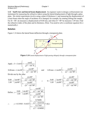
1.1 Maxwell's wave equation and plane waves
(a) Consider a traveling sinusoidal wave of the form Ex = Eo cos(ωt − kz + φo). The latter can also be
written as Ex = Eo cos[k(vt − z) + φo], where v = ω/k is the velocity. Show that this wave satisfies
Maxwell's wave equation, and show that v = (µoεoεr)−1/2
.
(b) Consider a traveling function of any shape, even a very short delta pulse, of the form Ex =
f[k(vt − z)], where f is any function, which can be written is Ex = f(φ), φ = k(vt − z). Show that this
traveling function satisfies Maxwell's wave equation. What is its velocity? What determines the form
of the function f?
Solution
(a)
Ex = Eo cos(ωt − kz + φo)
∴
2
2
0
x
E
x
∂
=
∂
and
2
2
0
x
E
y
∂
=
∂
and
2
2
2
cos( )
x
0 0
E
k E t kz
z
ω φ
∂
=
− − +
∂
∴
2
2
2
cos( )
x
0 0
E
E t kz
t
ω ω φ
∂
=
− − +
∂
Substitute these into the wave equation 0
2
2
2
2
2
2
2
2
=
∂
∂
−
∂
∂
+
∂
∂
+
∂
∂
t
E
z
E
y
E
x
E
o
r
o µ
ε
ε to find
2 2
cos( ) cos( ) 0
0 o r o 0 0
k E t kz E t kz
0 ω φ ε ε µ ω ω φ
− − + + + − + =
∴
2
2
1
o r o
k
ω
ε ε µ
=
∴
1
2
( )
o r o
k
ω
ε ε µ
−
=
∴
1
2
( )
o r o
ε ε µ
−
=
v
(b) Let
[ ( )] ( )
x
E f k t z f φ
= − =
v
Take first and second derivatives with respect to x, y, z and t.
Contact me in order to access the whole complete document.
WhatsApp: https://wa.me/message/2H3BV2L5TTSUF1
Email: smtb98@gmail.com
Telegram: https://t.me/solutionmanual
s
m
t
b
9
8
@
g
m
a
i
l
.
c
o
m
s
m
t
b
9
8
@
g
m
a
i
l
.
c
o
m
complete document is available on https://unihelp.xyz/ *** contact me if site not loaded](https://image.slidesharecdn.com/solutionmanualforoptoelectronicsphotonics2ndeditionbysafakasap-241218115803-b3c9adae/85/Solutions-for-Problems-in-Optoelectronics-Photonics-2nd-Edition-by-Safa-Kasap-1-320.jpg)
![Solutions Manual (Preliminary) Chapter 1 1.2
30 March 2017
Preliminary Solutions to Problems and Questions
Chapter 1
Note: Printing errors and corrections are indicated in dark red. See Question 1.47. These are
correct in the e-version of the textbook
1.1 Maxwell's wave equation and plane waves
(a) Consider a traveling sinusoidal wave of the form Ex = Eo cos(ωt − kz + φo). The latter can also be
written as Ex = Eo cos[k(vt − z) + φo], where v = ω/k is the velocity. Show that this wave satisfies
Maxwell's wave equation, and show that v = (µoεoεr)−1/2
.
(b) Consider a traveling function of any shape, even a very short delta pulse, of the form Ex =
f[k(vt − z)], where f is any function, which can be written is Ex = f(φ), φ = k(vt − z). Show that this
traveling function satisfies Maxwell's wave equation. What is its velocity? What determines the form
of the function f?
Solution
(a)
Ex = Eo cos(ωt − kz + φo)
∴
2
2
0
x
E
x
∂
=
∂
and
2
2
0
x
E
y
∂
=
∂
and
2
2
2
cos( )
x
0 0
E
k E t kz
z
ω φ
∂
=
− − +
∂
∴
2
2
2
cos( )
x
0 0
E
E t kz
t
ω ω φ
∂
=
− − +
∂
Substitute these into the wave equation 0
2
2
2
2
2
2
2
2
=
∂
∂
−
∂
∂
+
∂
∂
+
∂
∂
t
E
z
E
y
E
x
E
o
r
o µ
ε
ε to find
2 2
cos( ) cos( ) 0
0 o r o 0 0
k E t kz E t kz
0 ω φ ε ε µ ω ω φ
− − + + + − + =
∴
2
2
1
o r o
k
ω
ε ε µ
=
∴
1
2
( )
o r o
k
ω
ε ε µ
−
=
∴
1
2
( )
o r o
ε ε µ
−
=
v
(b) Let
[ ( )] ( )
x
E f k t z f φ
= − =
v
Take first and second derivatives with respect to x, y, z and t.
Contact me in order to access the whole complete document.
WhatsApp: https://wa.me/message/2H3BV2L5TTSUF1
Email: smtb98@gmail.com
Telegram: https://t.me/solutionmanual
s
m
t
b
9
8
@
g
m
a
i
l
.
c
o
m
s
m
t
b
9
8
@
g
m
a
i
l
.
c
o
m
complete document is available on https://unihelp.xyz/ *** contact me if site not loaded](https://image.slidesharecdn.com/solutionmanualforoptoelectronicsphotonics2ndeditionbysafakasap-241218115803-b3c9adae/75/Solutions-for-Problems-in-Optoelectronics-Photonics-2nd-Edition-by-Safa-Kasap-1-2048.jpg)
![Solutions Manual (Preliminary) Chapter 1 1.3
30 March 2017
2
2
0
x
E
x
∂
=
∂
2
2
0
x
E
y
∂
=
∂
x
E df
k
z dφ
∂
= −
∂
2 2
2
2 2
x
E d f
k
z dφ
∂
=
∂
x
E df
k
t dφ
∂
=
∂
v
2 2
2 2
2 2
x
E d f
k
t dφ
∂
=
∂
v
2 2 2 2
2 2 2 2
Substitute these into the wave equation 0
o r o
E E E E
x y z t
ε ε µ
∂ ∂ ∂ ∂
+ + − =
∂ ∂ ∂ ∂
to find
2 2
2 2 2
2 2
0
o r o
d f d f
k k
d d
ε ε µ
φ φ
− =
v
∴ 2 1
o r o
ε ε µ
=
v
∴
1
2
( )
o r o
ε ε µ
−
=
v
1.2 Propagation in a medium of finite small conductivity An electromagnetic wave in an
isotropic medium with a dielectric constant εr and a finite conductivity σ and traveling along z obeys
the following equation for the variation of the electric field E perpendicular to z,
t
E
t
E
dz
E
d
o
o
r
o
∂
∂
=
∂
∂
− σ
µ
µ
ε
ε 2
2
2
2
(1)
Show that one possible solution is a plane wave whose amplitude decays exponentially with
propagation along z, that is E = Eoexp(−α′z)exp[j(ωt – kz)]. Here exp(−α′z) causes the envelope of the
amplitude to decay with z (attenuation) and exp[j(ωt – kz)] is the traveling wave portion. Show that in
a medium in which α′ is small, the wave velocity and the attenuation coefficient α′ for the electric
field are given by
r
o
o
k ε
ε
µ
ω 1
=
=
v and
cn
o
ε
σ
α
2
=
′
where n is the refractive index (n = εr
1/2
). (Metals with high conductivities are excluded.)](https://image.slidesharecdn.com/solutionmanualforoptoelectronicsphotonics2ndeditionbysafakasap-241218115803-b3c9adae/85/Solutions-for-Problems-in-Optoelectronics-Photonics-2nd-Edition-by-Safa-Kasap-2-320.jpg)
![Solutions Manual (Preliminary) Chapter 1 1.4
30 March 2017
Note: The α′ in this problem characterize the decay rate of the field not the intensity. The actual α for
intensity would be twice the above α′ and hence it would be σ/εocn.
Solution
We can write E = Eoexp(−αz)exp[j(ωt – kz)] as E = Eoexp[jωt – j(k – jα)z]. Substitute this into the
wave resonance condition
[– j(k – jα)]2
Eoexp[jωt – j(k – jα)z] − (jω)2
εoεrµoEoexp[jωt – j(k – jα)z] =
jωµoσ Eoexp[jωt – j(k – jα)z]
∴ −(k – jα)2
+ ω2
εoεrµo = jωµoσ
∴ −k2
+ 2jkα – α2
+ ω2
εoεrµo = jωµoσ
Rearrange into real and imaginary parts and then equating the real parts and imaginary parts
∴ −k2
– α2
+ ω2
εoεrµo + 2jkα = jωµoσ
Real parts
−k2
– α2
+ ω2
εoεrµo = 0
Imaginary parts
2kα = ωµoσ
Thus,
n
n
c
k
k o
o
o
o
ε
σ
σ
µ
σ
µ
ω
σ
ωµ
α
2
2
2
2
=
=
⋅
=
=
where we have assumed ω/k = velocity = c/n (see below).
From the imaginary part
2
2
2
α
ε
ε
µ
ω −
= r
o
o
k
Consider the small α case (otherwise the wave is totally attenuated with very little propagation). Then
r
o
o
k ε
ε
µ
ω2
2
=
and the velocity is
r
o
o
k ε
ε
µ
ω 1
=
=
v
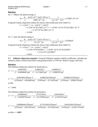
1.3 Point light source What is the irradiance measured at a distance of 1 m and 2 m from a 1 W
light point source?
Solution
Then the irradiance I at a distance r from O is
2
2
)
m
1
(
4
W
1
4 π
π
=
=
r
P
I o
= 8.0 µW cm-2
which drops by a factor of 4 at r = 2 m to become 2.0 µW cm-2
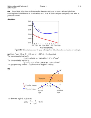
1.4 Gaussian beam A particular HeNe laser beam at 633 nm has a spot size of 0.8 mm. Assuming a
Gaussian beam, what is the divergence of the beam? What are its Rayleigh range and beam width at 10
m?
Solution
Using Eq. (1.1.7), we find,](https://image.slidesharecdn.com/solutionmanualforoptoelectronicsphotonics2ndeditionbysafakasap-241218115803-b3c9adae/85/Solutions-for-Problems-in-Optoelectronics-Photonics-2nd-Edition-by-Safa-Kasap-3-320.jpg)
![Solutions Manual (Preliminary) Chapter 1 1.5
30 March 2017
9
3
4 4(633 10 m)
2
(2 ) (0.8 10 m)
o
w
λ
θ
π π
−
−
×
= =
×
= 1.01×10⁻³
rad = 0.058°
The Rayliegh range is
3 2
2 1
2
9
[ (0.8 10 m)]
(633 10 m)
o
o
w
z
π
π
λ
−
−
×
= =
×
= 0.79 m
The beam width at a distance of 10 m is
2w = 2wo[1 + (z/zo)2
]1/2
= (0.8×10⁻³
m){1 + [(10 m)/(0.79 m)]2
}1/2
= 0.01016 m or 10.16 mm.
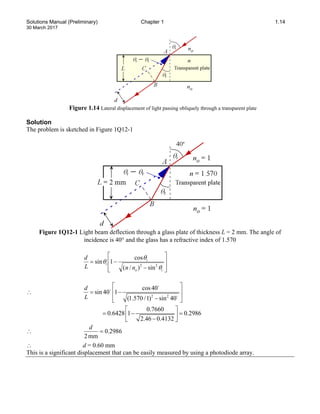
1.5 Gaussian beam in a cavity with spherical mirrors Consider an optical cavity formed by two
aligned spherical mirrors facing each other as shown in Figure 1.54. Such an optical cavity is called a
spherical mirror resonator, and is most commonly used in gas lasers. Sometimes, one of the reflectors
is a plane mirror. The two spherical mirrors and the space between them form an optical resonator
because only certain light waves with certain frequencies can exist in this optical cavity. The radiation
inside a spherical mirror cavity is a Gaussian beam. The actual or particular Gaussian beam that fits
into the cavity is that beam whose wavefronts at the mirrors match the curvature of the mirrors.
Consider the symmetric resonator shown in Figure 1.54 in which the mirrors have the same radius of
curvature R. When a wave starts at A, its wavefront is the same as the curvature of A. In the middle of
the cavity it has the minimum width and at B the wave again has the same curvature as B. Such a wave
in the cavity can replicate itself (and hence exist in the cavity) as it travels between the mirrors
provided that it has right beam characteristics, that is the right curvature at the mirrors. The radius of
curvature R of a Gaussian beam wavefront at a distance z along its axis is given by
R(z) = z[1 + (zo/z)2
] ; zo = πwo
2
/λ
is the Rayleigh range
Consider a confocal symmetric optical cavity in which the mirrors are separated by L = R.
(a) Show that the cavity length L is 2zo, that is, it is the same as the Rayleigh range, which is the reason
the latter is called the confocal length.
(b) Show that the waist of the beam 2wo is fully determined only by the radius of curvature R of the
mirrors, and given by
2wo = (2λR/π)1/2
(c) If the cavity length L = R = 50 cm, and λ = 633 nm, what is the waist of the beam at the center
and also at the mirrors?](https://image.slidesharecdn.com/solutionmanualforoptoelectronicsphotonics2ndeditionbysafakasap-241218115803-b3c9adae/85/Solutions-for-Problems-in-Optoelectronics-Photonics-2nd-Edition-by-Safa-Kasap-4-320.jpg)
![Solutions Manual (Preliminary) Chapter 1 1.6
30 March 2017
Figure 1.54 Two spherical mirrors reflect waves to and from each other. The optical cavity contains a
Gaussian beam. This particular optical cavity is symmetric and confocal; the two focal points coincide at F.
Solution
(a) At / 2
z R
= we have ( )
R z R
= . Substitute these into R(z) = z[1 + (zo/z)2
] to find
R = (R/2)[1 + (2zo/R)2
]
∴
2
2
1
2
+
=
R
zo
∴ 1
2
=
R
zo
∴ o
z
L 2
=
(b) R = (R/2)[1 + (2zo/R)2
]
∴
2
2
1
2
+
=
R
zo
∴ 1
2
=
R
zo
Now use zo = πwo
2
/λ,
∴ 1
2 2
=
λ
π
R
wo
∴
π
λ
R
wo
2
2 =
(c) Substitute λ = 633 nm, L = R = 50 cm into the above equation to find 2wo = 449 µm or 0.449 mm.
At the mirror, z = R/2, and also zo = R/2 so that
)
2
(
2
2
/
2
/
1
2
1
2
2 2
/
1
2
/
1
2
2
/
1
2
o
o
o
o w
R
R
w
z
z
w
w =
+
=
+
= = 0.635 mm
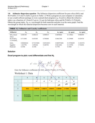
1.6 Cauchy dispersion equation Using the Cauchy coefficients and the general Cauchy equation,
calculate refractive index of a silicon crystal at 200 µm and at 2 µm, over two orders of magnitude
wavelength change. What is your conclusion?](https://image.slidesharecdn.com/solutionmanualforoptoelectronicsphotonics2ndeditionbysafakasap-241218115803-b3c9adae/85/Solutions-for-Problems-in-Optoelectronics-Photonics-2nd-Edition-by-Safa-Kasap-5-320.jpg)