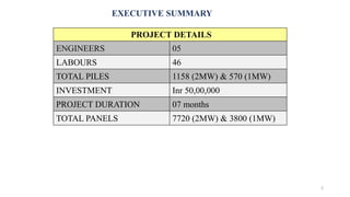
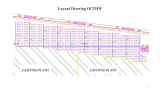
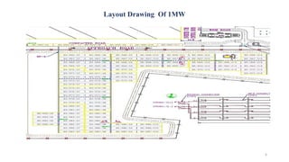
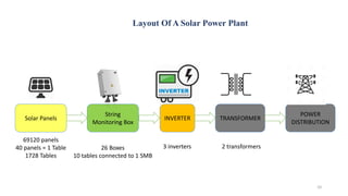
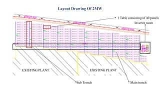
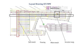
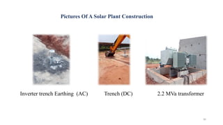
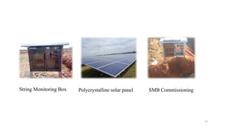
SOLAR POWER PLANT PROJECT
3MW SOLAR POWER PLANT
VEDHAAH POWER PLANT - DINDIGUL
CONTRACT : LARSEN & TOUBRO – POWER TRANSMISSION AND
DISTRIBUTION
SUB CONTRACT : RP STRUCTURAL SOLUTIONS
PRODUCED BY
A.WAJID SHARIEFF – FRONTLINE ENGINEER 1
EXECUTIVE SUMMARY
2
PROJECT DETAILS
ENGINEERS 05
LABOURS 46
TOTAL PILES 1158 (2MW) & 570 (1MW)
INVESTMENT Inr 50,00,000
PROJECT DURATION 07 months
TOTAL PANELS 7720 (2MW) & 3800 (1MW)
Layout Drawing Of 2MW
3
EXISTING PLANT EXISTING PLANT
Layout Drawing Of 1MW
4
Type Of Solar Panel Used
5
Types Of Solar Cell Efficiency Selection criteria
Monocrystalline 20% Expensive
Polycrystalline 15% Lower price
Thin-Film: Amorphous 10% Shorter life span
Concentrated PV 41% Cooling needed to reach high efficency
Selected
Specification Of TSM-315PC14
6
Specification Of Solar Panel
MAXIMUM POWER ( Pmax) 315W
MAXIMUM POWER VOLTAGE
(Vmp)
37.1V
MAXIMUM POWER CURRENT
(Imp)
8.51A
OPEN CIRCUIT VOLTAGE (Voc) 45.6V
SORT CIRCUIT CURRENT(Isc) 9.00A
MAXMIMUM SYSTEM VOLTAGE DC 1000V
MAXIMUM SERIES FUSE 15A
MODULE APPLICATION CLASS A
EFFICIENCY 16-20%
SIZE 1.94 x 1.94 metres
Life Span Of Polycrystalline Solar Cell
7
Type Of Transformer Used
8
Specification Of Transformer
TYPE OF TRANSFORMER Regulating Transformer
MAXIMUM CURRENT 25MVa
MAXIMUM VOLTAGE 33kV
PURPOSE Regulation
PHASE USED Three phase
Type Of Inverter Used - ABB central inverters CORE-500.0/1000.0-TL 500 to
1000 kW
9
Specification Of Inverter
TYPE OF INVETRER Indoor inverter
MAXIMUM POWER 500 – 1000 kW
OPEN CIRCUIT VOLTAGE
VOLTAGE
1000Voc
PURPOSE
For solar, operation in any
weather and environment
PHASE USED Three phase
DC INPUTS 12 pairs of inputs
ADVANTAGE Compact size and weight
SUPPLY CONNECTION 3 – phase
EFFICIENCY 98.7%
Layout Of A Solar Power Plant
10
Solar Panels
String
Monitoring Box
69120 panels
40 panels = 1 Table
1728 Tables
26 Boxes
10 tables connected to 1 SMB
INVERTER
3 inverters
TRANSFORMER
2 transformers
POWER
DISTRIBUTION
Design Calculation Of A Solar Power Plant
Total power needed = 3MWp / hour
• Maximum power obtained from each panel = 315W
Since 6 piles are connected to form a table, 40 panels are placed in a table.
So, power obtained per table = 315*40
= 12600W / hour
power obtained for 193 tables = 12600*193
= 2.431MW (DC) / hour
Power needed for 95 tables = 12600*95
= 1.197MW (DC) / hour
So as per the requirement the power obtained is 2.4318+1.197 = 3.6288(DC) / hour
Upon conversion from DC through inverter to AC some power is lost which is then
boosted by a transformer.
11
Work Content In Constructing A Solar Plant
• Civil department
• Mechanical department
• Electrical department
12
The above departments are interconnected to each other. First comes civil, then mechanical and
finally electrical.
Work Content Of A Civil Department
• The civil department consists of surveying, pile casting and inverter room
construction. The pile marking is done by a surveyor and pile alignment is done.
• The pile alignment is done as depth of 1200 millimetres and diameter of 300
millimetres as per drawing by L&T.
• A single table consists of 6 piles and the distance of each pile is 3500mm and
6500mm horizontally.
• The pile casting is done by filling the hole by concrete in the ratio 1:2:3, that is
cement : sand : blue metal.
• Then coping is done of 75mm height and 150mm diameter ( as per the drawing).
• After the field work, the inverter room is constructed. The inverter room ids
constructed with ventilators and ducts.
• The inverter room is constructed as one inverter for each room. For example
1MW=1 inverter and a transformer.
• Further finishing is done by interior works and painting.
13
Pile Drawing
14
Diagram Of Civil Work Content
15
Pile
Coping
Concrete casting
Schematic Function Of A Civil Department
16
Land clearing Survey marking and pile drilling Pile alignment
Pile castingInverter room construction
Work Content Of A Mechanical Department
• The rafter is to be place at 8 – 9 degrees. The structure is made of galvanised iron
which is iron coated with zinc. This prevents corrosion.
• The purlin, rafter, brazing channel, connecting channel are connected to the stub.
• The grade of the nut bolt and washer used is M8 for a fixed type solar bed. Two
plain washer and one spring washer is used.
• The nut is of M8 * 25mm, the plain washer is of M8 * 2.5mm and spring washer
M8 * 2.5mm.
• The torque value is 58 N – mm for tightening the purlin and rafter with the stub.
• the nut, bolt and washer is made up of GI material.
• The length is of 1027mm and purlin is of 3957mm.
17
Structure Of A Solar Panel Mounting
The following components are used in a fixed type solar plant
• Purlin ( 3Nos.)
• Brazing connecting channel (1Nos.)
• Cleat plate (6Nos.)
• Brazing (2Nos.)
• Rafter (1Nos.)
18
Purlin
Cleat plate
Rafter
Brazing connecting channel
Stub
Concrete
Brazing
Work Content Of A Electrical Department
• The electrical work content consisted of two parts, AC and DC.
• The power from solar panel is DC and the power from inverter to distribution is
AC.
• The DC work starts with digging trench of depth 900mm as per the diagram.
Through these trench the DC cable, string cable and communication cable passes.
• The trench connects all the SMBs. For every 10 tables one SMB is connected.
• The power ( DC cable) from each and every table connects a SMB and from SMB
the communication connects the inverter in the inverter room.
• The SMB is connected by a string cable of 4sq.mm specification and DC cable of
300sq.mm specification.
• From inverter to the distribution line AC passes. The inverter room consists of a
inverter/MW a high tension panel and a transformer.
19
• The type of inverter used is of three phase string inverter from ABB
• The transformer used is of 2.2 MVa.
• The inverter room carries AC cables that are placed on a separate trays called cable trays.
• There are two types of trays used one is ladder trays and another, perforated trays.
• Perforated trays contain communication cables and ladder trays contain other AC cables
that are to be connected to the inverter to transformer.
• The size of those cables is 1core 300sq.mm.
• The inverter room consists of pulling pits having two holes through which the cables from
the field enters the room.
• The use of a string monitoring box is to collect all the information from the panels and
send it for monitoring. A SCADA software is used to monitor the exact power production
from the field.
• Then the power production is distributed to the destiny.
• The trench diagram is shown in the next slide. The blue line indicates the trench across
the field.
20
Layout Drawing Of 2MW
Sub Trench Main trench
1 Table consisting of 40 panels
EXISTING PLANT EXISTING PLANT
Inverter room
Layout Drawing Of 1MW
22
Sub trench Main trenchFencing Inverter room
DC Cables Laying Task
• The DC cable is laid across the trench. Main trench and the sub trench has to laid
with different type of cables.
• The sub trench is to be laid with a conduit pipe of radius 500mm and length
1000mts along with 1core 4 sq. mm of length varying from 1000-2000mts. The
conduit pipe connects the SMB.
• From SMB the 1core 300 sq. mm connects the inverter.
• There are four layers in a trench, first will be the rammed sand of 75mm and next
will be the conduit pipe (in case of a sub trench) or other DC cables ( in case of a
main trench), and then will be dry sand and one layer of brick of 75 mm height.
• Then the communication cable of type (RS485) and then warning tape is laid.
• Then the sand is filled. And a warning tape is provided as a caution. The whole
height of the trench is 900m.
• There are three steps in cable laying cable shifting, cable laying, cable glanding,
cable termination.
23
Layout Of Main Trench
24
Layout Of A Sub Trench
25
Layout Of SMB To Panel Connection
26
Layout Of Panel Connection To SMB
27
AC Cables Laying Task
• The AC cable is laid from the SMB to inverter and to transformer. The inverter
room consists of cable trays supported by L- angles, a pulling pit connecting the
DC cables and a pipe line to transformer.
• There are two types of trays used ladder type and a perforated type of tray. The
ladder type tray is used to provide maximum ventilation to heat. It is used to
support insulated electric cables for power distribution and communication.
• The perforated type cable tray have uniform holes. They are suitable for cables
that require both protection from external damage and ventilation.
• The dimension of a ladder type tray used is 600*150mm and the perforated tray
used is 300*150mm. The cables that are connected to inverter through ladder and
perforated trays.
• The inverter, HT panel is placed upon C- channel, which acts as a support.
• The C- channels are welded to provide a support to the inverter.
28
Ladder And Perforated Type Tray
29
30
Inverter trench Earthing (AC) Trench (DC) 2.2 MVa transformer
Pictures Of A Solar Plant Construction
String Monitoring Box Polycrystalline solar panel SMB Commissioning
31
Conclusion
Solar power systems derive clean, pure energy from the sun. Installing solar plants,
helps combat greenhouse gas emissions and reduces our collective dependence on
fossil fuel. Traditional electricity is sourced from fossil fuels such as coal and
natural gas, but production of electricity from solar cell is much more effective.
Solar energy systems generally don’t require a lot of maintenance. You only need to
keep them relatively clean, so cleaning them a couple of times per year will do the
job.Thus in this project after laying, glanding and terminating the cables with SMB,
inverter and with Transformer, the commissioning is done. The solar panels are
interconnected to form a closed loop. And it is checked to achieve the necessary
power. If the power is achieved then the power is distributed otherwise the power
cable is checked for its losses.The project was completed successfully as it achieved
3MWp / hour, and handed over to the client for distribution.
32

Solar Power Plant At Dindigul

  • 1.
    SOLAR POWER PLANTPROJECT 3MW SOLAR POWER PLANT VEDHAAH POWER PLANT - DINDIGUL CONTRACT : LARSEN & TOUBRO – POWER TRANSMISSION AND DISTRIBUTION SUB CONTRACT : RP STRUCTURAL SOLUTIONS PRODUCED BY A.WAJID SHARIEFF – FRONTLINE ENGINEER 1
  • 2.
    EXECUTIVE SUMMARY 2 PROJECT DETAILS ENGINEERS05 LABOURS 46 TOTAL PILES 1158 (2MW) & 570 (1MW) INVESTMENT Inr 50,00,000 PROJECT DURATION 07 months TOTAL PANELS 7720 (2MW) & 3800 (1MW)
  • 3.
    Layout Drawing Of2MW 3 EXISTING PLANT EXISTING PLANT
  • 4.
  • 5.
    Type Of SolarPanel Used 5 Types Of Solar Cell Efficiency Selection criteria Monocrystalline 20% Expensive Polycrystalline 15% Lower price Thin-Film: Amorphous 10% Shorter life span Concentrated PV 41% Cooling needed to reach high efficency Selected
  • 6.
    Specification Of TSM-315PC14 6 SpecificationOf Solar Panel MAXIMUM POWER ( Pmax) 315W MAXIMUM POWER VOLTAGE (Vmp) 37.1V MAXIMUM POWER CURRENT (Imp) 8.51A OPEN CIRCUIT VOLTAGE (Voc) 45.6V SORT CIRCUIT CURRENT(Isc) 9.00A MAXMIMUM SYSTEM VOLTAGE DC 1000V MAXIMUM SERIES FUSE 15A MODULE APPLICATION CLASS A EFFICIENCY 16-20% SIZE 1.94 x 1.94 metres
  • 7.
    Life Span OfPolycrystalline Solar Cell 7
  • 8.
    Type Of TransformerUsed 8 Specification Of Transformer TYPE OF TRANSFORMER Regulating Transformer MAXIMUM CURRENT 25MVa MAXIMUM VOLTAGE 33kV PURPOSE Regulation PHASE USED Three phase
  • 9.
    Type Of InverterUsed - ABB central inverters CORE-500.0/1000.0-TL 500 to 1000 kW 9 Specification Of Inverter TYPE OF INVETRER Indoor inverter MAXIMUM POWER 500 – 1000 kW OPEN CIRCUIT VOLTAGE VOLTAGE 1000Voc PURPOSE For solar, operation in any weather and environment PHASE USED Three phase DC INPUTS 12 pairs of inputs ADVANTAGE Compact size and weight SUPPLY CONNECTION 3 – phase EFFICIENCY 98.7%
  • 10.
    Layout Of ASolar Power Plant 10 Solar Panels String Monitoring Box 69120 panels 40 panels = 1 Table 1728 Tables 26 Boxes 10 tables connected to 1 SMB INVERTER 3 inverters TRANSFORMER 2 transformers POWER DISTRIBUTION
  • 11.
    Design Calculation OfA Solar Power Plant Total power needed = 3MWp / hour • Maximum power obtained from each panel = 315W Since 6 piles are connected to form a table, 40 panels are placed in a table. So, power obtained per table = 315*40 = 12600W / hour power obtained for 193 tables = 12600*193 = 2.431MW (DC) / hour Power needed for 95 tables = 12600*95 = 1.197MW (DC) / hour So as per the requirement the power obtained is 2.4318+1.197 = 3.6288(DC) / hour Upon conversion from DC through inverter to AC some power is lost which is then boosted by a transformer. 11
  • 12.
    Work Content InConstructing A Solar Plant • Civil department • Mechanical department • Electrical department 12 The above departments are interconnected to each other. First comes civil, then mechanical and finally electrical.
  • 13.
    Work Content OfA Civil Department • The civil department consists of surveying, pile casting and inverter room construction. The pile marking is done by a surveyor and pile alignment is done. • The pile alignment is done as depth of 1200 millimetres and diameter of 300 millimetres as per drawing by L&T. • A single table consists of 6 piles and the distance of each pile is 3500mm and 6500mm horizontally. • The pile casting is done by filling the hole by concrete in the ratio 1:2:3, that is cement : sand : blue metal. • Then coping is done of 75mm height and 150mm diameter ( as per the drawing). • After the field work, the inverter room is constructed. The inverter room ids constructed with ventilators and ducts. • The inverter room is constructed as one inverter for each room. For example 1MW=1 inverter and a transformer. • Further finishing is done by interior works and painting. 13
  • 14.
  • 15.
    Diagram Of CivilWork Content 15 Pile Coping Concrete casting
  • 16.
    Schematic Function OfA Civil Department 16 Land clearing Survey marking and pile drilling Pile alignment Pile castingInverter room construction
  • 17.
    Work Content OfA Mechanical Department • The rafter is to be place at 8 – 9 degrees. The structure is made of galvanised iron which is iron coated with zinc. This prevents corrosion. • The purlin, rafter, brazing channel, connecting channel are connected to the stub. • The grade of the nut bolt and washer used is M8 for a fixed type solar bed. Two plain washer and one spring washer is used. • The nut is of M8 * 25mm, the plain washer is of M8 * 2.5mm and spring washer M8 * 2.5mm. • The torque value is 58 N – mm for tightening the purlin and rafter with the stub. • the nut, bolt and washer is made up of GI material. • The length is of 1027mm and purlin is of 3957mm. 17
  • 18.
    Structure Of ASolar Panel Mounting The following components are used in a fixed type solar plant • Purlin ( 3Nos.) • Brazing connecting channel (1Nos.) • Cleat plate (6Nos.) • Brazing (2Nos.) • Rafter (1Nos.) 18 Purlin Cleat plate Rafter Brazing connecting channel Stub Concrete Brazing
  • 19.
    Work Content OfA Electrical Department • The electrical work content consisted of two parts, AC and DC. • The power from solar panel is DC and the power from inverter to distribution is AC. • The DC work starts with digging trench of depth 900mm as per the diagram. Through these trench the DC cable, string cable and communication cable passes. • The trench connects all the SMBs. For every 10 tables one SMB is connected. • The power ( DC cable) from each and every table connects a SMB and from SMB the communication connects the inverter in the inverter room. • The SMB is connected by a string cable of 4sq.mm specification and DC cable of 300sq.mm specification. • From inverter to the distribution line AC passes. The inverter room consists of a inverter/MW a high tension panel and a transformer. 19
  • 20.
    • The typeof inverter used is of three phase string inverter from ABB • The transformer used is of 2.2 MVa. • The inverter room carries AC cables that are placed on a separate trays called cable trays. • There are two types of trays used one is ladder trays and another, perforated trays. • Perforated trays contain communication cables and ladder trays contain other AC cables that are to be connected to the inverter to transformer. • The size of those cables is 1core 300sq.mm. • The inverter room consists of pulling pits having two holes through which the cables from the field enters the room. • The use of a string monitoring box is to collect all the information from the panels and send it for monitoring. A SCADA software is used to monitor the exact power production from the field. • Then the power production is distributed to the destiny. • The trench diagram is shown in the next slide. The blue line indicates the trench across the field. 20
  • 21.
    Layout Drawing Of2MW Sub Trench Main trench 1 Table consisting of 40 panels EXISTING PLANT EXISTING PLANT Inverter room
  • 22.
    Layout Drawing Of1MW 22 Sub trench Main trenchFencing Inverter room
  • 23.
    DC Cables LayingTask • The DC cable is laid across the trench. Main trench and the sub trench has to laid with different type of cables. • The sub trench is to be laid with a conduit pipe of radius 500mm and length 1000mts along with 1core 4 sq. mm of length varying from 1000-2000mts. The conduit pipe connects the SMB. • From SMB the 1core 300 sq. mm connects the inverter. • There are four layers in a trench, first will be the rammed sand of 75mm and next will be the conduit pipe (in case of a sub trench) or other DC cables ( in case of a main trench), and then will be dry sand and one layer of brick of 75 mm height. • Then the communication cable of type (RS485) and then warning tape is laid. • Then the sand is filled. And a warning tape is provided as a caution. The whole height of the trench is 900m. • There are three steps in cable laying cable shifting, cable laying, cable glanding, cable termination. 23
  • 24.
    Layout Of MainTrench 24
  • 25.
    Layout Of ASub Trench 25
  • 26.
    Layout Of SMBTo Panel Connection 26
  • 27.
    Layout Of PanelConnection To SMB 27
  • 28.
    AC Cables LayingTask • The AC cable is laid from the SMB to inverter and to transformer. The inverter room consists of cable trays supported by L- angles, a pulling pit connecting the DC cables and a pipe line to transformer. • There are two types of trays used ladder type and a perforated type of tray. The ladder type tray is used to provide maximum ventilation to heat. It is used to support insulated electric cables for power distribution and communication. • The perforated type cable tray have uniform holes. They are suitable for cables that require both protection from external damage and ventilation. • The dimension of a ladder type tray used is 600*150mm and the perforated tray used is 300*150mm. The cables that are connected to inverter through ladder and perforated trays. • The inverter, HT panel is placed upon C- channel, which acts as a support. • The C- channels are welded to provide a support to the inverter. 28
  • 29.
  • 30.
    30 Inverter trench Earthing(AC) Trench (DC) 2.2 MVa transformer Pictures Of A Solar Plant Construction
  • 31.
    String Monitoring BoxPolycrystalline solar panel SMB Commissioning 31
  • 32.
    Conclusion Solar power systemsderive clean, pure energy from the sun. Installing solar plants, helps combat greenhouse gas emissions and reduces our collective dependence on fossil fuel. Traditional electricity is sourced from fossil fuels such as coal and natural gas, but production of electricity from solar cell is much more effective. Solar energy systems generally don’t require a lot of maintenance. You only need to keep them relatively clean, so cleaning them a couple of times per year will do the job.Thus in this project after laying, glanding and terminating the cables with SMB, inverter and with Transformer, the commissioning is done. The solar panels are interconnected to form a closed loop. And it is checked to achieve the necessary power. If the power is achieved then the power is distributed otherwise the power cable is checked for its losses.The project was completed successfully as it achieved 3MWp / hour, and handed over to the client for distribution. 32