For download link head to http://solarreference.com/solar-cooling-training-presentation/
Also available from SOLAIR website.
A presentation from the SOLAIR project on sizing of solar air conditioners. their website has a lot of details information. For similar useful resources visit us on http://solarreference.com
Solar photovoltaic thermal (PV/t) parabolic trough collector systemManav Shah
This system consists of concentrating parabolic trough collector to magnify the solar radiation onto the focal point where absorber tube has been placed. Working fluid such as water is passed from the tube with the help of pump. In order to increase the overall efficiency of the system, photovoltaic cells are placed on the absorber tube so that hot water and electricity can be produced from one integrated system.
Il CSP di piccola taglia e l’accumulo termico: le attività di ricerca in cors...Sardegna Ricerche
L'intervento di Giorgio Cau (Università di Cagliari) in occasione dell'evento "Solare termodinamico di piccola taglia: impianti dimostrativi in Sardegna e calore di processo industriale" che si è tenuto a Pula (CA) il 25 settembre 2015.
Design of a Power Generation System for Lunar Applicationsmattkopecki
As a part of U of I’s Mechanical Engineering program, this presentation was created for the ME 470 senior design / capstone project. This work was completed for Boeing and is not under NDA.
Thermal Efficiency of Buildings - Stefan Huber - Paul Heat Recovery ScotlandEuro Energy Services
At Euro Energy Services Renewable Energy in Scotland Open Day on October 23rd Stefan Huber talked about how the thermal efficiency of buildings and why well designed ventilation is vital to buildings.
ORC ElectraTherm Green Machine - waste heat to power, Power generationRado Irgl
ElectraTherm's Green Machine converts low temperature water flows into fuel-free, emission-free electric power. The Green Machine output range is from 20 kWe to 65kWe, based on temperatures and flows.
The Green Machine, is an Organic Rankine Cycle (ORC) based heat-to-power generating system. It captures waste energy from small, distributed hot water sources such as stationary engine jacket water, biomass boilers, solar thermal and co-produced (or geothermal) fluids to generate 25 - 65kWe of fuel-free, emissions-free electricity. Factory assembled and tested, it is skid mounted and available as a single unit or in multiples to match the available heat.
The patented twin screw expander and ElectraTherm’s ORC system specifically targets low temperature and abundant resources. Our current upper limit for input to the machine is 240°F/116°C. However, if there is potential to reduce the hot water source via a secondary loop, the Green Machine can be utilized.
A biogas plant that uses the Green Machine converts excess engine heat
into valuable electricity and reduces existing on-site electrical cooling loads
for the engine. The Green Machine increases biogas plant efficiency and lowers fuel requirements for the biogas engine. This means increased revenue
for the biogas plant.
http://www.cogenera.si/
At Euro Energy Services Renewable Energy in Scotland Open Day on October 23rd Thomas Dickson of Glow Worm discusses Air Source Heat Pumps and their application in dwellings across the UK
Presented by Dr. Jein Yoo, Korean Association for Energy Service Companies, KAESCO, Korea at the IEA DSM Programme workshop in Seoul, Korea on 18 April 2007.
one of the renewable energy resources project that help me lot to my carrier in research field : this slide is for the prototype model that i design actual full scale size may be bit of different from my calculations and data's
SOLAR POWER VAPOUR ABSORPTION REFRIGERATION SYSTEMaj12345ay
USE OF SOLAR POWER IN REFRIGERATION SYSTEM
The power incident from the sun to the earth has very much amount of energy that the present consumption rate of all the commercial and general uses. We utilize only 0.1% of total incident sun energy on the surface of earth. Thus solar energy can fulfill our present as well as future needs of energy. That is a reason it called renewable sources of energy. It is also environmental clean source of energy and available at whole part of world where people live. Using of solar energy in the field of refrigeration and air conditioning system it become very economical.
In our project we provide solar heat in generator for heating purpose of vapor compression refrigeration system.
For past few decades, energy has played a prominent role in the development of technology and economy. Energy has now become inevitable factor for production as well. The objective of this project is to develop an environment friendly vapour absorption system. Vapour absorption system uses heat energy, instead of mechanical energy as in vapour compression system, in order to change the condition of refrigerant required for the operation of the cycle. R 717(NH3) and water are used as working fluids in this system. The basic idea of this project is derived from the solar heating panel to obtain heat energy, instead of using any conventional source of heat energy. In this project various observations are done by varying operating conditions related to heat source, condenser, absorber and evaporator temperatures. The drawback of this system is that, it remains idle in the cloudy weather conditions.
COMPONENTS USED IN SOLAR POWERED AQUA-AMMONIA VAPOUR ABSORPTION SYSTEM
• ABSORBER
• PUMP
• HEAT EXCHANGER
• GENERATOR
• SOLAR PANEL
• CONDENSER
• EXPANSION VALVE
• EVAPORATOR
• DC BATTERY
• FAN
A solar PV array system is comprised of the following components - solar cells, panel modules, and an array system. Thus, overall optimal design of a solar PV system involves the optimal design of the components at three levels - solar cell, panel module, and array. In the present work, a comparison between different optimization methods is applied to design optimization of single channel Photovoltaic (SCPVT) system. The purpose of these methodologies is to obtain optimum values of the design parameters of SCPVT system, such that the overall economic profit is maximized throughout the PV system lifetime operational period which is not directly calculated in our work rather energy efficiency is calculated . Out of many design parameters available for this system, in the present work only few parameters are taken. The optimal design parameters chosen here are length of channel, depth of channel, velocity of fluid in the cell, and temperature of the cell. The objective function of the proposed optimization algorithm which is Gravitational Search Algorithm (GSA) implemented for design optimization of the system is the energy efficiency, which has to be maximized.
Process heat requirement constitutes a large part of global energy demand. Solar thermal harnesses heat from the sun that can be effectively used for process heat requirements, and save upto 30% cost when compared to conventional energy sources like gas, diesel, electricity etc.
HMX offers solar thermal solutions for steam generation and high-temperature hot water for a range of applications such as process heating, CIP (clean in place), pasteurization, distillation, cooking, air heating, etc., across industries and commercial establishments.
Concentrated Solar Power Course - Session 1 : FundamentalsLeonardo ENERGY
Lesson 1 : Fundamentals of concentrating solar thermal power
In this session, the contents will focus on the physical and thermodynamic basis of Concentrated Solar Power:
* High temperature solar-thermal conversion, limits to the concentration of solar radiation and description of the main concentrating technologies.
* Solar thermal power plants: concept, background, general configuration and main typologies of solar thermal power plants.
Design Calculations for Solar Water Heating Systemsangeetkhule
Chapter 1 City of Residence
Chapter 2 Estimation of Available Solar Resources
Chapter 3 Site Survey
Chapter 4 Load Estimation
Chapter 5 Estimation of Required Absorber Area
Chapter 6 Market Survey & Estimation of No. of Tubes for ETC
Chapter 7 Economical Analysis & Estimation of Payback Period
Chapter 8 Conclusion
Presentation given by Dr Maria Chiara Ferrari from University of Edinburgh on "Capturing CO2 from air: Research at the University of Edinburgh" at the UKCCSRC Direct Air Capture/Negative Emissions Workshop held in London on 18 March 2014
Presented by P.C. Incalcaterra, "White Certificates Evaluation Team", ENEA, Italy, at the IEA DSM Programme workshop in Milan, Italy on 22 October 2008.
Solar Resource Assessment - How to get bankable meteo dataSolarReference
Available for download at http://solarreference.com/solar-resource-assessment-how-to-get-bankable-meteo-data/
This presentation from DLR (German Aerospace Center) explains.
1. Solar radiation data characteristics
2. How radiation data is gathered from ground measurements and derived from satellite data
3. Comparison of the two, and some important factors to be weighed in when deciding what to use
This presentation can also be downloaded at NREL
This presentation explores the food-energy-water nexus in light of renewable energy for food preservation. It provides information on projects taken up by TERI for commercialising renewable powered small scale cold storages
This document has been prepared using the publicly available version from UNDP. To download, head to - solarreference.com/users-handbook-on-solar-water-heaters/
Also available from UNDP site. This handbook on solar water heaters provides organized information to users about the different technologies and equipment available, and the costs involved in installing solar water heaters.
Solar resource measurements and sattelite dataSolarReference
To access explanatory notes and download link, head to -
http://solarreference.com/all-you-need-to-know-about-solar-resource-measurement/
This presentation can also be downloaded for SFERA website (SFERA Summer School 2013). Amazing, concise, to the point document. For more quality resources, visit
http://solarreference.com
This presentation details out fire safety issues with small PV systems, and related safety best practices. Several links are available directing to more detailed reports. For more similar free resources on renewable energy please visit http://solarreference.com/
For direct download link, visit:
http://solarreference.com/what-you-need-to-design-rural-mini-grids/
The “Mini Grid Design Manual” would be useful to anyone wanting to design generation-to-house wiring systems for simple village level grids. With detailed theory as well as practical advice, it is very much relevant today as it was when published back in 2000.
To download, head to -
http://solarreference.com/parabolic-trough-collectors-comparison/
A detailed comparison of different types of parabolic trough collectors on the basis of specifications, technology, material etc. If CSP is your arena, this is one presentation you just can't miss !!!
Source: NREL
For more quality resources visit us at http://solarreference.com
To download, head to - http://solarreference.com/cspalliance-csp-thermal-energy-storage-presentation/
Also available at CSP alliance website. Key information includes - direct comparison of a CSP power plant with a conventional power plant, importance of thermal energy storage and the fact that deployment would lead to much more cost reduction than r&d.
For colelction of similar resources, head to -
http://solarreference.com
To download head to http://solarreference.com/solar-pv-codes-brooks/
Also available on the Brook Solar website (they have some quality stuff)
This presentation from Brook Solar (Now Brooks Engineering LLC) is a wonderful compilation of the standards in place in the PV industry. But you do know that standards are like babies, they don't stop growing!
For more quality information visit http://solarreference.com/
Neuro-symbolic is not enough, we need neuro-*semantic*Frank van Harmelen
Neuro-symbolic (NeSy) AI is on the rise. However, simply machine learning on just any symbolic structure is not sufficient to really harvest the gains of NeSy. These will only be gained when the symbolic structures have an actual semantics. I give an operational definition of semantics as “predictable inference”.
All of this illustrated with link prediction over knowledge graphs, but the argument is general.
Software Delivery At the Speed of AI: Inflectra Invests In AI-Powered QualityInflectra
In this insightful webinar, Inflectra explores how artificial intelligence (AI) is transforming software development and testing. Discover how AI-powered tools are revolutionizing every stage of the software development lifecycle (SDLC), from design and prototyping to testing, deployment, and monitoring.
Learn about:
• The Future of Testing: How AI is shifting testing towards verification, analysis, and higher-level skills, while reducing repetitive tasks.
• Test Automation: How AI-powered test case generation, optimization, and self-healing tests are making testing more efficient and effective.
• Visual Testing: Explore the emerging capabilities of AI in visual testing and how it's set to revolutionize UI verification.
• Inflectra's AI Solutions: See demonstrations of Inflectra's cutting-edge AI tools like the ChatGPT plugin and Azure Open AI platform, designed to streamline your testing process.
Whether you're a developer, tester, or QA professional, this webinar will give you valuable insights into how AI is shaping the future of software delivery.
State of ICS and IoT Cyber Threat Landscape Report 2024 previewPrayukth K V
The IoT and OT threat landscape report has been prepared by the Threat Research Team at Sectrio using data from Sectrio, cyber threat intelligence farming facilities spread across over 85 cities around the world. In addition, Sectrio also runs AI-based advanced threat and payload engagement facilities that serve as sinks to attract and engage sophisticated threat actors, and newer malware including new variants and latent threats that are at an earlier stage of development.
The latest edition of the OT/ICS and IoT security Threat Landscape Report 2024 also covers:
State of global ICS asset and network exposure
Sectoral targets and attacks as well as the cost of ransom
Global APT activity, AI usage, actor and tactic profiles, and implications
Rise in volumes of AI-powered cyberattacks
Major cyber events in 2024
Malware and malicious payload trends
Cyberattack types and targets
Vulnerability exploit attempts on CVEs
Attacks on counties – USA
Expansion of bot farms – how, where, and why
In-depth analysis of the cyber threat landscape across North America, South America, Europe, APAC, and the Middle East
Why are attacks on smart factories rising?
Cyber risk predictions
Axis of attacks – Europe
Systemic attacks in the Middle East
Download the full report from here:
https://sectrio.com/resources/ot-threat-landscape-reports/sectrio-releases-ot-ics-and-iot-security-threat-landscape-report-2024/
"Impact of front-end architecture on development cost", Viktor TurskyiFwdays
I have heard many times that architecture is not important for the front-end. Also, many times I have seen how developers implement features on the front-end just following the standard rules for a framework and think that this is enough to successfully launch the project, and then the project fails. How to prevent this and what approach to choose? I have launched dozens of complex projects and during the talk we will analyze which approaches have worked for me and which have not.
Dev Dives: Train smarter, not harder – active learning and UiPath LLMs for do...UiPathCommunity
💥 Speed, accuracy, and scaling – discover the superpowers of GenAI in action with UiPath Document Understanding and Communications Mining™:
See how to accelerate model training and optimize model performance with active learning
Learn about the latest enhancements to out-of-the-box document processing – with little to no training required
Get an exclusive demo of the new family of UiPath LLMs – GenAI models specialized for processing different types of documents and messages
This is a hands-on session specifically designed for automation developers and AI enthusiasts seeking to enhance their knowledge in leveraging the latest intelligent document processing capabilities offered by UiPath.
Speakers:
👨🏫 Andras Palfi, Senior Product Manager, UiPath
👩🏫 Lenka Dulovicova, Product Program Manager, UiPath
PHP Frameworks: I want to break free (IPC Berlin 2024)Ralf Eggert
In this presentation, we examine the challenges and limitations of relying too heavily on PHP frameworks in web development. We discuss the history of PHP and its frameworks to understand how this dependence has evolved. The focus will be on providing concrete tips and strategies to reduce reliance on these frameworks, based on real-world examples and practical considerations. The goal is to equip developers with the skills and knowledge to create more flexible and future-proof web applications. We'll explore the importance of maintaining autonomy in a rapidly changing tech landscape and how to make informed decisions in PHP development.
This talk is aimed at encouraging a more independent approach to using PHP frameworks, moving towards a more flexible and future-proof approach to PHP development.
Essentials of Automations: Optimizing FME Workflows with ParametersSafe Software
Are you looking to streamline your workflows and boost your projects’ efficiency? Do you find yourself searching for ways to add flexibility and control over your FME workflows? If so, you’re in the right place.
Join us for an insightful dive into the world of FME parameters, a critical element in optimizing workflow efficiency. This webinar marks the beginning of our three-part “Essentials of Automation” series. This first webinar is designed to equip you with the knowledge and skills to utilize parameters effectively: enhancing the flexibility, maintainability, and user control of your FME projects.
Here’s what you’ll gain:
- Essentials of FME Parameters: Understand the pivotal role of parameters, including Reader/Writer, Transformer, User, and FME Flow categories. Discover how they are the key to unlocking automation and optimization within your workflows.
- Practical Applications in FME Form: Delve into key user parameter types including choice, connections, and file URLs. Allow users to control how a workflow runs, making your workflows more reusable. Learn to import values and deliver the best user experience for your workflows while enhancing accuracy.
- Optimization Strategies in FME Flow: Explore the creation and strategic deployment of parameters in FME Flow, including the use of deployment and geometry parameters, to maximize workflow efficiency.
- Pro Tips for Success: Gain insights on parameterizing connections and leveraging new features like Conditional Visibility for clarity and simplicity.
We’ll wrap up with a glimpse into future webinars, followed by a Q&A session to address your specific questions surrounding this topic.
Don’t miss this opportunity to elevate your FME expertise and drive your projects to new heights of efficiency.
1. Training course on solar cooling
Chapter C :
Predesign – system sizing
funded by
Speaker:
XXXX YYYYY
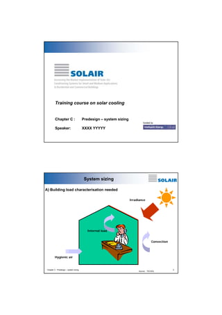
System sizing
A) Building load characterisation needed
Irradiance
Internal load
Convection
Hygienic air
Chapter C : Predesign – system sizing
Source : TECSOL
2
5. Primary energy analysis
primary
primary
energy
energy
conversion
conversion
factor for
factor for
electricity:
electricity:
0.36
0.36
2.5
COP = 0.6
COP = 0.8
COP = 1.0
COP = 1.2
Conv 2
Conv, 1
2.0
PEspec,sol , kWhPE/kWhcold
heat source:
heat source:
solar collector
solar collector
+ fossil fueled
+ fossil fueled
backup
backup
1.5
COPconv =
2.5
1.0
0.5
primary
primary
energy
energy
conversion
conversion
factor for
factor for
fossil fuels: 0.9
fossil fuels: 0.9
COPconv =
4.5
0.0
0
0.1
0.2
0.3
0.4
0.5
0.6
0.7
0.8
0.9
1
Solar Fraction for cooling
Chapter C : Predesign – system sizing
9
Source : Fraunhofer ISE
Comparison between absortion and compression
Efficiency based on primary energy
2
specific primary energy per unit of cold
1.5
1
thermal system,
low COP
no primary
energy
saving
0.5
conventional system
thermal system,
high COP
saves primary
energy
0
0
0.1
0.2
0.3
0.4
0.5
0.6
0.7
0.8
0.9
1
solar fraction cooling
Chapter C : Predesign – system sizing
Source : Aiguasol
10
6. Consequences of primary energy performance
! High solar fraction for cooling necessary for solar thermally driven cooling
equipment with low COP which use a fossil fueled backup
! A lower solar fraction is acceptable if thermally driven cooling equipment with a
higher COP is employed
! An alternative is to use a conventional chiller as a backup (e.g. in case of a large
overall cooling power)
! Primary energy savings are always achieved using a solar thermally autonomous
systems but no guarantee for strictly keeping desired indoor comfort limits can
be given
! In any case the use of the solar collector should be maximised by supplying heat
also to other loads such as the heating system or hot water production
Chapter C : Predesign – system sizing
11
Design
Design with regard to solar-assisted air-conditioning mainly means
! Selection of the proper thermally driven cooling equipment for the
selected air-conditioning system
! Selection of the proper type of solar collectors for the selected airconditioning system and thermally driven cooling equipment
! Sizing of the solar collector field and other components of the solar
system with regard to energy and cost performance
Chapter C : Predesign – system sizing
12
7. ‚Rules of thumb‘
Collector cost per heating
capacity
Cost of solar heat for
given climate
Load - gain - analysis for
given climate and load
Anual cost based on loadgain-analysis
Computer design tool with
predefined systems
Open simulation platform
Chapter C : Predesign – system sizing
Required system information, effort for parametrization
Accuracy, reliability of results, details of design information
Design approaches
Source : Fraunhofer ISE
13
Design point
Acoll ⋅ Gcoll ⋅ ηcoll,design =
==
>
Aspec =
Example
Pcold,design
COP
design
1
Gcoll ⋅ ηcoll,design ⋅ COP
design
Gcoll = 800 W/m2
hcoll,design = 0.5
==>
Aspec = 3.57 m2 per kW cooling power
COPdesign = 0.7
Chapter C : Predesign – system sizing
Source : Fraunhofer ISE
14
8. Advantages and disadvantages
+ Method allows a very quick assessment (guess) about the
required collector area, if the efficiency of the collector and
the COP of the thermally driven cooling equipment is
known
– Method neglects completely the influence of the variation
of radiation on the collector during day and year
– Any information on the specific site and load is neglected
– Method neglects completely part load conditions of cooling
load in thermally driven cooling equipment
Chapter C : Predesign – system sizing
15
Sizing
Average values of the
specific collector area
" for Absorption- and
Adsorption chillers
3,0 to 3,5 m²/kW
chilling capacity
" for open technologies
(DEC, liquid DEC):
8 to 10 m² per 1.000 m³/h
rated air flowrate
Source : EAW
Chapter C : Predesign – system sizing
16
9. Collector first cost
average fluid
temperature
η = k(Θ) ⋅ c0 − c1 ⋅
incident
angle
modifier
optical
efficiency
&
Quse = A ⋅ η ⋅ G⊥
⇒
ambient air
temperature
(T − T )2
(Tav − Tamb)
− c 2 ⋅ av amb
G⊥
G⊥
linear
heat loss
coeff.
A=
&
Quse
η ⋅ G⊥
radiation on
collector
quadr.
heat loss
coeff.
⇒
Aspec =
Costheat,power = Aspec ⋅ Costspec
1 kW
η ⋅ G⊥
specific
collector cost
average fluid temperature = operating hot temperature of cooling system
Chapter C : Predesign – system sizing
Source : Fraunhofer ISE
17
collector first cost [€/kW]
Collector cost versus specific required area
2000
Tav = 75°C
Gcoll = 800 W/m2
1600
1200
800
400
0
1
2
3
4
5
6
required absorber area [m2/kW]
evacuated tube
Chapter C : Predesign – system sizing
flat plate
flat plate - integrated roof
stationary CPC
Source : Fraunhofer ISE
18
10. Advantages and disadvantages
+ Method allows a rough comparison of different solar
collectors, if the collector parameters and the operation
temperature of the thermally driven cooling equipment are
known
– Method neglects completely the influence of the variation
of radiation on the collector during day and year
– Any information on the specific site and load is neglected
– Method neglects completely part load of cooling load and
thermally driven cooling equipment
Chapter C : Predesign – system sizing
19
Solar heat cost
Costannual = Costspec ⋅ fannuity
annual
collector cost
solar heat
cost (€/kWh
of heat)
spedific
collector cost
(€/m2)
Costheat =
Costannual
Qgross
annuity
factor
collector gross
heat
production
Qgross = annual collector heat productionat a given site and a given operationtemperatur .
e
Typically calculatedu sing hourly values of the dominating meteorological data.
Chapter C : Predesign – system sizing
Source : Fraunhofer ISE
20
11. Solar heat cost
heat cost [€-cent/kWh]
20
etc
fpc
irc
Palermo, Tav = 75°C
cpc
16
12
8
4
0
0
200
400
600
800
1000
1200
1400
2
annual gross heat production [kWh/m ]
Source : Fraunhofer ISE
Chapter C : Predesign – system sizing
21
Solar heat cost
heat cost [€-cent/kWh]
20
etc
fpc
irc
Palermo, Tav = 95°C
cpc
16
12
8
4
0
0
200
400
600
800
1000
1200
1400
annual gross heat production [kWh/m2]
Chapter C : Predesign – system sizing
Source : Fraunhofer ISE
22
12. Simple software tool SHC (NEGST project)
Only needs monthly cooling (heating) load
Free download in:
http://www.swt-technologie.de/html/publicdeliverables3.html
Compares monthly loads
(heating and coling) with
monthly solar energy
gains.
It is based on
PHIBARFCHART Method
- The results are primary
energy savings for
colector area installed.
Chapter C : Predesign – system sizing
23
Advantages and disadvantages
+ Method allows a good comparison of different solar
collectors using their parameters and the radiation data of
a specific site
+ The maximum possible heat production of a specific solar
collector for a given site (annual meteorological data file)
and a given constant operation temperature is determined
– Any information about the load profile is neglected
– Method neglects completely part load of cooling load and
thermally driven cooling equipment
Chapter C : Predesign – system sizing
24
13. Correlation of loads and gains
! Global efficiency factors for
transformation of heat in
cooling (heating) are used
to describe the technical
equipment
! Calculation of hourly
collector gains using
different operation
temperatures for cooling
and heating
Chapter C : Predesign – system sizing
meteo data
building
model
collector
model
250
heating
cooling
1
0.5
0.25
0.1
200
COP, ε
heat load
! For each hour of the year
the required heat for
cooling (heating) is
computed, e.g. using
building simulation
150
100
50
0
0
100
200
300
400
500
600
700
800
solar gains
solar fractions for
heating and cooling
Source : Fraunhofer ISE
25
Software tools needed to determine hourly
cooling (heating) loads of a building
TRNSYS – Commercially available
(www.sel.me.wisc.edu/trnsys/)
Energy plus – Download free
(www.eere.energy.gov/buildings/energyplus/ )
ESP-r – Download free
(http://www.esru.strath.ac.uk/Programs/ESP-r.htm )
A list of other software tools can be found :
(http://www.eere.energy.gov/buildings/tools_directory/)
Chapter C : Predesign – system sizing
26
14. Simple software tools using hourly
cooling (heating) load
SACE Cooling evaluation light tool
– available in http://www.solair-project.eu/218.0.html
Results using this software tool while be shown latter
Chapter C : Predesign – system sizing
27
Simple software tools using hourly
cooling (heating) load
SolAC – available in:
http://www.iea-shc-task25.org/english/hps6/index.html
Four different units are considered in this software:
• Solar system
• Cooling device
• Air handling unit
• Cooling and heating components in the room
The input data for the
programme is:
• weather data including solar
radiation (hourly data)
• load files including heating
and cooling loads (hourly
data)
Chapter C : Predesign – system sizing
28
15. Dynamic simulation software tools using
hourly cooling (heating) load
- System orientated
TNSYS - www.sel.me.wisc.edu/trnsys/
ColSim - www.colsim.de
Insel - http://www.inseldi.com/index.php?id=21&L=1
- Building Orientated
Energy plus - www.eere.energy.gov/buildings/energyplus/
Software
Solar
Components
AC
Components
New
Components
TRNSYS
ColSim
Yes
Yes
Yes
Yes
Energy
Plus
INSEL
Yes
Yes
Yes, but no
clear list was
possible to
obtain.
Yes
Free
Open
downlaod source
code
No
Yes
Not clear Yes
Yes
Yes
Not clear
Yes
Yes
Yes
NO
NO
Chapter C : Predesign – system sizing
29
Identification of HVAC components available which are most interesting for
CTSS
TRNSYS 16.
Type 107 – Absorption Chiller (hot water fired, single effect)
Type 51 – Cooling Towers.
TESS Libraries
Type 680 – Single-effect hot water-fired absorption chiller (Equivalent to type
107 of TRNSYS 16)
Type 679 – Single-effect steam-fired absorption chiller
Type 677 – Double-effect hot water-fired absorption chiller
Type 676 – Double-effect steam-fired absorption chiller
Type 683 – Rotary desiccant dehumidifier – models a rotary dessicant
dehumidifier containing nominal silica gel.
Chapter C : Predesign – system sizing
30
16. Calculation methods :
Estimated calculation with energy balances
Solar thermal energy availability
• Simulation tool for the solar systems
• “Infinite” consumption with high return temperature (chilled water)
• 100% use of produced solar energy
Energy load determination, per year and per month: cold, heat, and DHW
• Calculation tool for the building energy load
• DHW energy load determination
Use factor determination
• Depends on the relation availability / load
• Depends on the heat storage
solar
absorció
gas
caldera
elect
bomba
calor
calefacció
refrigeració
Definition of energy flows between subsystems
• -> Definition of a control strategy
Chapter C : Predesign – system sizing
Chapter C : Predesign – system sizing
Source : Aiguasol
Source : Fraunhofer ISE
31
32
17. Guidelines for design, control & operation
of solar assisted adsorption chillers
COPsol =
COPsol =
Radiation on
Radiation on
2
collector: 800 W/m 2
collector: 800 W/m
0.6
COP, COPsol, etacoll
COP * ηcoll
COP * ηcoll
90
80
0.5
70
0.4
60
0.3
50
0.2
40
etacoll
COP
COPsol
0.1
COP-maximum
at about 70°C
cooling power
cooling power, kW
0.7
30
0
20
60
65
70
75
80
85
90
95
temperature, °C
Chapter C : Predesign – system sizing
33
Source : Fraunhofer ISE
Efficiency of solar thermal cooling systems
0.60
Irradiation W/m2
0.50
500
600
700
800
900
1000
COPsolar
0.40
0.30
0.20
0.10
==> optimal
working
temperature
depends on the
irradiation level
0.00
Chapter C : Predesign – system sizing
60
80
100
120
140
160
180
200
Working temperature [°C]
Source : Fraunhofer ISE
34
18. Evaluation parameter: Costs of saved
primary energy
! Combined Energy-costs-Performance
! enables comparison of different system designs
Costs of primary
energy saved
∆total annual costs ==annual supplementary costs of the solar
∆total annual costs annual supplementary costs of the solar
=
driven system compared to aa
driven system compared to
conventional
reference system
conventional
reference system
∆ Total annual costs
∆ Primary energy
∆primary energy
∆primary energy
==annual primary energy saving of
annual primary energy saving of
the solar driven system compared to aa
the solar driven system compared to
conventional reference system
conventional reference system
Source : Fraunhofer ISE
Chapter C : Predesign – system sizing
35
Example: primary energy savings
Growing collector
surface
! Office
buildings
! Flat plate
( in % of the reference system)
! Madrid
Primary energy saved
60%
50%
40%
30%
! Backup:
Gas boiler
! Absorption
Collector surface,
m2
20%
collector
160
180
200
220
240
260
280
10%
55
65
75
85
95
105
115
125
135
2
Storage volume, l/m
chiller
Chapter C : Predesign – system sizing
Source : Fraunhofer ISE
36
20. System sizing
Dynamic modelling with TRNSYS… necessary
Chapter C : Predesign – system sizing
39
Transient simulation – TRNSYS
TRNSYS features
– Numerical calculation methods
– Continuous yearly simulation of the thermal behaviour of the
installation, analysing the transitory phenomenon of the heat
flows
– Variability of climatology (temperature, irradiation) is taken into
account
– Enables analysis of the different factors which determine the
energetic behaviour of the system # parametric study#
optimisation
Chapter C : Predesign – system sizing
40
21. Transient simulation – TRNSYS
TRNSYS Workspace
Chapter C : Predesign – system sizing
41
Transient simulation – TRNSYS
Results obtained with TRNSYS
Chapter C : Predesign – system sizing
42
22. Transient simulation – TRNSYS
35
30
Analysis of the results
25
20
Tamb
Tair
15
7000
Monthly heating demand in kWh
Total demand in kWh
6000
10
5
Solar contribution in kWh
0
5000
1
14 27 40 53 66 79 92 105 118 131 144 157
kWh
4000
3000
2000
1000
0
Gener
Febrer
Març
Abril
Maig
Juny
Juliol
Agost
Setembre Octubre NovembreDesembre
Chapter C : Predesign – system sizing
43
Transient simulation – TRNSYS
Calculation options with dynamic simulation tools
Separated calculation of building and cooling system
– Step 1: Simulation of the building demand (heating, cooling)
– Cooling system model= ideal system with infinite power.
– Intermediate result: hourly data of heating and cooling demand.
– Step 2: Simulation of the cooling system
– Result: energy contribution of the real cooling system
Coupled calculation of the building and the cooling system
– Simulation of the building (demand) and of the cooling system in the
same software
–
Cooling system model = real system
– Results:
• Energy contribution of the real cooling system
• Degree of fulfilment of the comfort criteria
Chapter C : Predesign – system sizing
44
23. Which questions have to be answered?
1. Which is the basic sizing of the main equipments?
• Collector field : type and size in m2
• Absorption machine: kWf
2. What is the solar contribution to the cooling, heating and global demand?
3. Which is the basic sizing of the back-up system?
• type (boiler, heat pump, air conditioner...);
• size kW
4. Which are the energy savings?
5. What are the additional costs compared to a conventional installation?
6. What is the pay-back time?
Chapter C : Predesign – system sizing
45
Chapter C : Predesign – system sizing
46
24. Rules of Thumb – pre-design rules of
solar cooling systems
Sizing of the absorption machine
Demand peak < maximal total power (absorption + auxiliaries) + cold
storage
Operating with solar energy: minimal power required to absorb the
solar heat produced and convert it into cold. # 3 m2/kWf
– Criteria 1: the absorption machine is able to use the maximal
solar production. Solar peak production approx. 0.5 kW/m2
(1000 W/m² x 50 % efficiency)
kWf
kW
kW
kW
m2
0.65
× 0.5 solar ×1 gen = 0.32 2f = 3
kWgen
m2
kWsolar
m
kWf
– Criteria 2: the solar energy produced during the day of maximal
irradiation can be totally used by the absorption machine,
assuming that the required heat storage is available
– Maximal power to guarantee a minimal solar contribution
(typically > 60...70 %) and/or an reasonable number of operating
hours (> 1000 h/year).
Chapter C : Predesign – system sizing
47
Rules of Thumb – pre-design rules of
solar cooling systems
Sizing of the heat/cold storage
Cold storage
– Cover demand peaks (smaller machines, larger number of
operating hours)
– Avoid part-load or intermittent operation
Heat storage
– Gap between cooling demand and solar heat availability
– Guarantee continuous operation of the machine during days of
intermittent irradiation
– Typical size: 25 .. 50 litres / m2 of collector
Chapter C : Predesign – system sizing
48
25. Rules of Thumb – pre-design rules of
solar cooling systems
Control strategy
Starting priority (cold production) according to the energy efficiency
– Cold production with heat-pump in case of simultaneous heat
demand. Solar contribution for space heating.
– Cold production with absorption through solar heat
– Cold production with heat-pump (without heat recovery)
– Cold production with absorption through gas boiler
Chapter C : Predesign – system sizing
49
System sizing
127 kW
85 kW
700W/m²
75 – 95°C
75 – 95°C
200 m²
25 - 35°C
77 kW
7 – 12 °C
Chapter C : Predesign – system sizing
50
kWf
Source : TECSOL
50
26. System sizing
1 Cooling load : 50 kWc
! 2 Inlet generator : 50 / 0.65 = 77 kW
! 3 Cooling tower : 77 + 50 = 127 kW
! 4 Primary loop efficiency : 0.9
! 5 Heat load on collector side : 85 kW
! 6 Average irradiance : 700 W/m²
! 7 Collector efficiency : 0.6
! 8 Collector area : 85/0.7/0.6 = 200 m²
! 9 Optimal tilt : 30° (France South)
! 10 Groung space necessary > 300 m²
!
Chapter C : Predesign – system sizing
51
Check list concept : example
Industry
3
3
3
2
2
Space for technical premices
3
2
1
Adapted distribution network
3
3
2
Adapted existing material (or planned) for back up
3
3
3
Daily adequation production <-> load
3
3
1
Yearly adequation production <-> load
3
2
2
Yearly heating and DHW needs
3
2
2
Passives actions decrease potential
3
3
3
Possible undersizement of solar system thanks to
back up
TECHNICAL
FEASIBILITY
Hotel
3
Important area for solar collection
Building
Public building
Climate
3
3
2
Load
Chapter C : Predesign – system sizing
Source : TECSOL
52
27. Check list concept : example
Industry
3
3
2
2
3
3
1
Building owner motivation
3
3
3
Importance in term of marketing impact
3
2
3
Environmental action politics
3
3
3
National & international supports eligibility
1
3
2
Financial stability of building owner
3
3
1
Skilled internal technical staff
3
2
2
Regulat operation action possibilities
FEASIBILITY
3
High investment capacity
ECONOMICAL
Hotel
1
Low water cost
Cost of energy
Public building
High cost of saved energy
3
2
2
Presence of a long term financed monitoring
2
3
2
58
55
45
Building owner
ORGANISAT.
O&M
FEASIBILITY
Monitoring
TOTAL SCORE
(on 63) :
Source : TECSOL
Chapter C : Predesign – system sizing
53
Disclaimer
This training has been developed in the context of SOLAIR. SOLAIR is a European cooperation project for increasing the market implementation of solar-air-conditioning
systems for small and medium applications in residential and commercial buildings. For
further information on the project or on products of the project see: www.solairproject.eu
The project SOLAIR is supported by the Intelligent Energy – Europe (IEE) programme of
the European Union promoting energy efficiency and renewables. More details on the
IEE programme can be found on: http://ec.europa.eu/energy/intelligent/index_en.html
The sole responsibility for the content of this training lies with the authors. It does not
represent the opinion of the European Communities. The European Commission is not
responsible for any use that may be made of the information contained therein.
Chapter C : Predesign – system sizing
54