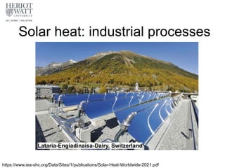
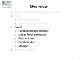
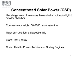
This document provides an overview of solar thermal energy conversion. It discusses different types of solar collectors, including flat plate collectors and evacuated tube collectors. It also describes several methods for concentrating solar power including parabolic trough collectors, linear Fresnel reflectors, Fresnel towers, and parabolic dish collectors. The document outlines the basic components and functioning of solar thermal power plants that use these concentrating collectors to generate electricity.


![Efficiency of Solar Collectors
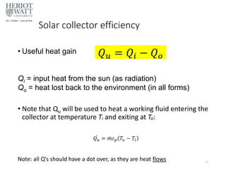
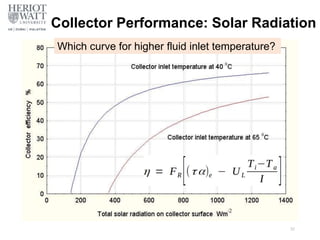
Rate of heat loss:
UL collector overall heat loss coefficient [W/m/K]
A area, m²
TC collector average temperature [°C]
Ta ambient temperature [°C]
21](https://image.slidesharecdn.com/week7solar-thermal-240313014137-89b9303a/85/Solar-Thermal-in-power-generation-for-cleaner-18-320.jpg)


![Case Study:
Crescent Dune
• Bloomberg: "A $1 Billion Solar
Plant Was Obsolete Before
It Ever Went Online"
• ten thousand mirrors form a
spiral almost 2 miles wide
(Nevada – USA)
• designed to generate enough
power night and day to supply
a population of 100,000
• its energy costs about $135/MWh, compared with less than
$30/MWh today at a new Nevada photovoltaic solar farm
[BloombergNEF]
https://www.bloomberg.com/news/articles/2020-01-06/a-1-billion-solar-plant-was-obsolete-before-it-ever-went-online](https://image.slidesharecdn.com/week7solar-thermal-240313014137-89b9303a/85/Solar-Thermal-in-power-generation-for-cleaner-52-320.jpg)