Downloaded 83 times


![1 Eck, M.; Hennecke, K.: Heat transfer fluids for future parabolic trough solar
thermal power plants. In:
Goswami, D. Yogi; Zhao, Yuwen [Ed.]: ISES Solar World Congress 2007, ISES Solar
World Congress, Beijing
(China), S. 1806 - 1812.
2 Benz N.: Next generation receivers, NREL Trough Work Shop, March 7-8,
Golden,
http://www.nrel.gov/csp/troughnet/wkshp_2007.html (2007).
3 Zarza, E.; Valenzuela, L.; León, J.; Hennecke, K.; Eck, M.; Weyers, H.-D.;
Eickhoff, M.: Direct Steam
Generation in Parabolic Troughs - Final Results and Conclusions of the DISS
Project, Energy, Vol. 29 (2004),
pp. 635-644.
4 Nava, P.; Hermann, U.: Trough Thermal Storage - Status Spring 2007, NREL
Trough Work Shop, March 7-8,
Golden, http://www.nrel.gov/csp/troughnet/wkshp_2007.html (2007).
5 Steinmann, W.-D.; Tamme, R.: Latent heat storage for solar steam systems, 13th
International Symposium on
Concentrated Solar Power and Chemical Energy Technologies, June 20-23 (2006)
Seville, Spain.](https://image.slidesharecdn.com/seminarppt-160923155503/85/Direct-steam-generation-from-solar-27-320.jpg)


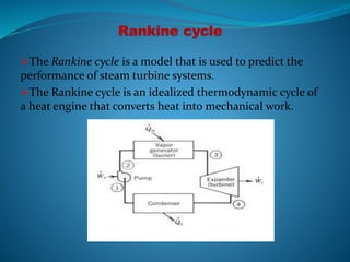
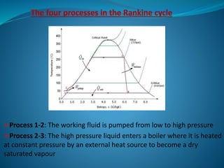
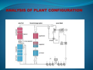
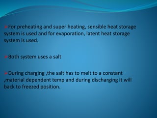
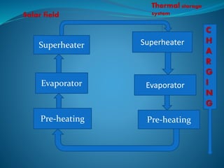
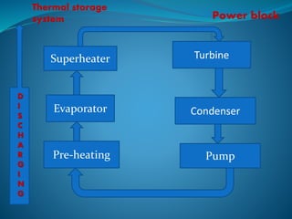
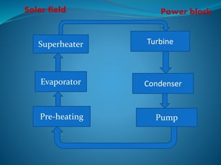
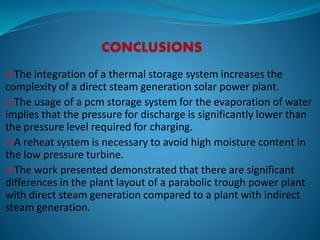
The document discusses the Rankine cycle, its processes, and the usage of solar-thermal power plants for electricity generation with thermal storage systems. It highlights the principles of parabolic trough collectors and the potential of using molten salts as phase change materials for efficient heat storage. Additionally, it addresses challenges related to pressure requirements during charging and discharging and suggests that integration of thermal storage increases the complexity and efficiency of direct steam generation solar power plants.


