
Recommended
Recommended
More Related Content
What's hot
What's hot (20)
Similar to Solar and Electric Powered Hybrid Vehicle
Similar to Solar and Electric Powered Hybrid Vehicle (20)
More from ijtsrd
More from ijtsrd (20)
Recently uploaded
Recently uploaded (20)
Solar and Electric Powered Hybrid Vehicle
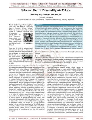
- 1. International Journal of Trend in Scientific Research and Development (IJTSRD) Volume: 3 | Issue: 4 | May-Jun 2019 Available Online: www.ijtsrd.com e-ISSN: 2456 - 6470 @ IJTSRD | Unique Paper ID – IJTSRD24038 | Volume – 3 | Issue – 4 | May-Jun 2019 Page: 1009 Solar and Electric Powered Hybrid Vehicle Ma Naing1, May Thwe Oo2, New Nwe Oo1 1Lecturer, 2Professor 1,2Department of Electronic Engineering, Technological University, Magway, Myanmar How to cite this paper: Ma Naing | May Thwe Oo | New Nwe Oo "Solar and Electric Powered Hybrid Vehicle" Published in International Journal of Trend in Scientific Research and Development (ijtsrd), ISSN: 2456- 6470, Volume-3 | Issue-4, June 2019, pp.1009-1012, URL: https://www.ijtsrd.c om/papers/ijtsrd24 038.pdf Copyright © 2019 by author(s) and International Journal of Trend in Scientific Research and Development Journal. This is an Open Access article distributed under the terms of the Creative Commons Attribution License (CC BY 4.0) (http://creativecommons.org/licenses/ by/4.0) ABSTRACT This system is designed to prevent green-house effect caused duetotheburning of fossil fuel and reduce pollution for the environment. The designing, construction and implementation of the Solar and Electric Powered Hybrid Vehicle (SEPHV) are expressed in this paper. The powersupplyof theSEPHV can be charged by the solar and normal AC power source too. In this system, the series combination of 12V six lead-acid batteries is used for the driving motor power supply (40~60V DC). The 50W six solar panels are used for charging each of batteries. The charge controller is designed to be the supplybatterieswith the minimum amount charge possible and to protect from overcharge by the solar panels as well as over discharge by the driving motor. In this SEPHV, wireless message display system is also designed by Arduino software. The weight of the car without load is 300kg. As the results, this SEPHV is capable of accommodating at least fourpersons(250kg) withanaveragespeedof57km/hr. By using this, we can be able to reduce the all kind pollutions and fuel economy. Keywords: BLDC motor, Solar Panel, Charge Controller, Battries, Speed Controller, Arduino I. INTRODUCTION The fossil fuel such as petrol and diesel are very expensive way to be extracted and used. , Transportation of these fuel in rural areas themselves have become a problem. The major problem is green-house effect caused due to this burning of fossil fuel. Solar vehicles depend on PV cells to drive the BLDC motors. Unlike solar thermal energy which converts solar energy to heat, PV cells directly convert sunlight into electricity. The Solar and Electric Powered Hybrid Vehicle(SEPHV)contains the solar panel, Brushless DC (BLDC) motor, charge controller, batteries, speed controller and inverter. Inverter can be used to charge the batteries in normal AC supply during sunless conditions. A zero emission solar/electric vehicle is powered by Photovoltaic/Electric Supply energy by means of solar panels and AC supply with storages of electric energy in batteries. The PV array has a particular operating point that can supply the maximum power to the load which is generally called Maximum Power Point (MPP). The SEPHV can charge itself from both solar and electric power. The vehicle is altered by replacing its engine with a 1600W, 60V brushless DC (BLDC) motor.Theelectricsupply to the motor is obtained from six battery set of 60V, 20AH. Six solar panels each with a rating of 60W, 20A are attached to the top of the vehicle to grab the solar energy and then it is controlled with the help of charge controller. This is used as a main source of energy to charge the battery. The household electric supply of 220V is reduced with a inverter to 12V and then it is converted it to DC with a rectifying unit to charge the battery. This is used as a backup source or auxiliary of energy to charge the battery. The Vehicle can be controlled and can matchup a speed. The Solar and Electric Powered Hybrid Vehicle (SEPHV) is thus a boom to the present world by providing us with fuel free mode of transport. II. System Block Diagram Solar and Electric Powered Hybrid Vehicle (SEPHV) is altered by replacing its engine with Brushless DC Motor (BLDC). The Motor is made to run from a batterysetwhich is charged from two methods. In the first method , SolarPanels are kept at the top of the SEPHV which produces a DC Voltage from the availability of solar radiation. The amount of DC voltage developed is controlled using a charge controller. For the second method, the normal AC Supply is stepped down and rectified to produce a DC Voltage. These two methods are combined to charge the batteries. The charge controller controls the depth of discharge (DOD) of the battery in order to maintain the life of the battery. The motor controller can be used to control both the speed and its electrical braking. Solar charging controllersaredesigned to prevent solar and electric hybrid vehicle (SEPHV) from overcharging and excessive discharging,thereforetoprotect our investment and extend the battery life. The electrical energy thus formed is being fed to the batteries that get charged and is used to run 60V BLDC motor. The batteries are initially fully charged by PV panels and electric supply. The batteries are directly connected to the motor through a Solenoid control circuit. The Solenoids are acting as the speed control switch. Initially, first accelerator contact is pressed where the Solenoid-I activatesandthesinglebattery is connected to the motor. When the second accelerator contact is pressed, solenoid-II activates and the two set of batteries are connected to the motor. When the third accelerator contact is pressed, solenoid-III activates and the IJTSRD24038
- 2. International Journal of Trend in Scientific Research and Development (IJTSRD) @ www.ijtsrd.com eISSN: 2456-6470 @ IJTSRD | Unique Paper ID – IJTSRD24038 | Volume – 3 | Issue – 4 | May-Jun 2019 Page: 1010 three set of batteries are connected to the motor. When the fourth accelerator contact is pressed solenoid-IV activates and the four set of batteries are connected to the motor. In this method it acts as a voltage control method. Fig.1: System Block Diagram of the SEPHV III. Design of SEPHV Fig2: Front View Fig3: Top View Fig4: Side View Fig5: Wheel Axel Fig6: Suspension System Fig7: Steering System Fig8: Breaking System IV. System components 1. Solar Panel Polycrystalline silicon solar panels are selected for this system. Polycrystalline silicon solar panels use less silicon, which makes them somewhat less efficient. However, the
- 3. International Journal of Trend in Scientific Research and Development (IJTSRD) @ www.ijtsrd.com eISSN: 2456-6470 @ IJTSRD | Unique Paper ID – IJTSRD24038 | Volume – 3 | Issue – 4 | May-Jun 2019 Page: 1011 unique design, which features strips of silicon wrapped around rectangular conduct wires, allows them to function more efficiently. Certain circumstantialuseofpolycrystalline silicon solar panels such as when used on rooftops can yield efficiency. 2. Charge Controler These are simple controllers which use basictransistorsand relays to control the voltage by either disconnecting or shorting the panel to the battery. Maximum Power Point Tracking (MPPT): These types of controllers are highly efficient and provide the battery with 15-30% more power. MPPT Controllers track the voltage of the battery and match the panel output with this. This ensures maximumchargeby converting the high output from solar panels to a lower voltage needed to charge the batteries. Pulse Width Modulated Design (PWM). 3. Battery Lead Acid Batteries can contain a large amount of electrical energy which they are capable of discharging very quickly if any form of conductor is placed across their terminals. Lead acid batteries contain sulfuric acid which is corrosive. Lead acid batteries give off hydrogen when they are being charged, which when mixed with air is explosive, and can be ignited by small spark. 4. BLDC Motor In BLDC motor, the current carrying conductor is stationary while the permanent magnet moves. When the stator coils are electrically switched by a supply source, it becomes electromagnet and starts producing the uniform field in the air gap. Though the source of supply is DC, switching makes to generate an AC voltage waveform with trapezoidal shape. Due to the force of interaction between electromagnetstator and permanent magnet rotor, the rotor continues to rotate. V. Wireless Message Display System A Dot Matrix Display (DMD) Board is a matrix of LED connected in 16x32 pattern. Messages can be transferred over mobile to DMD Board using Bluetooth. The connection of the hardware components is highlighted below. The Bluetooth module is connected as shown with thepins0and 1 of the Arduino connected to the TX and RX of Bluetooth module respectively and powered by VCC (5V) and GND of the Arduino. To control the DMD, the connection on the Arduino Uno of Pins 6 to 13, and GND of the Arduino board were used. The software used in this work consists of two parts. The first is the code for communication between the Arduino Bluetooth and the mobile phone and the second is the mobile application used to send the text from the mobile to the LCD screen. Fig8: System Flow Chart
- 4. International Journal of Trend in Scientific Research and Development (IJTSRD) @ www.ijtsrd.com eISSN: 2456-6470 @ IJTSRD | Unique Paper ID – IJTSRD24038 | Volume – 3 | Issue – 4 | May-Jun 2019 Page: 1012 VI. Results Fig9: Charging System Fig10: Displaying the Message on DMD Board Fig11: The SEPHV VII. Discussion This paper is discussed about fossil fuel that are considered as an essential and ideal source of energy. This paper shows that solar car can reach the velocity 57 km/h and it is stable and safe of main results. A solar car is powered by a BLDC motor. While gasoline vehicle have a heavynoise andpollute the air, solar electric vehicle are smooth and silent and also have on pollution emits while driving. The idea of solar vehicle is new. This system composed of Solar panel, Brushless DC Motor, Charge Controller, 12 V lead acid batteries, and speed control for driving smaller parts. The individual experience that each oneof ushasbeen throughis priceless and very informative and knowledgeable. We learned more about power generation and utilizing renewable energy. We eventually had a chance to put what we have learned in a real life project. This was basically achieved due to dedication, passion and hard work. There are a couple of pointers that were concluded at the end of our project. Those are: Implementation of Electric Cars is possible in Myanmar. Solar Panel can be used in Electric cars in Myanmar to have cleaner energy, due to abundance of sunlight throughout the year. VIII. Further Extension In the near future, the SEPHV can be designed and constructed with the remote control steering which will be able to move the SEPHV as the driver's wish. Therefore, the driver will control the movement and speed of the solar car. The car can be created with suitable chassis, advance suspension and breaking system to be flexible and comfortable. In this SEPHV, only one BLDC motor is used for driving the car but we can improve the performances of the car by increasing the number and powerof motor.Solarcars will be easily incorporated with future technologies. IX. References [1] M. A. Spina, R. J. de la vega, S. R. Rossi etc, “Source issues on the design of a solar vehicle based on hybrid energy system” International Journal of Energy Engineering, 2012,2(1): 15-21 [2] S. Lalouni, D. Rekioua, T. Rekioua and E. Matagne, “Fuzzy logic control of standalone photovoltaicsystem with battery storage”, Journalof powersystem,volume 193, Issue 2, 5 September 2009, pp 899-907. [3] R. Mangu, K. Prayaga, B. Nadimpally and S. Nicaise, “Design, Development and Optimization of highly efficient solar cars: gato Del sol I-IV”, in proc. IEEE Green Technology Conference, 2010, 1-6. [4] Iqbal Husain, “Electrical and Hybrid Vehicles Design Fundamentals” by CRC Press Boca Raton London New York Washington, D.C. [5] T. J. E. Miller, “Brushless Permanent Magnet and Reluctance motor drive”, Clarendon pressoxford1989. [6] Oliver Trembly, Louis A. Dessaint and Abdel-Illah Dekkiche, “A Generic Battery model for the Dynamic Simulation of Hybrid Electric Vehicles”, 2007, pp.284- 289. [7] Dakshina M. Bellur and Marian K. Kazimierczuk, “DC- DC Converters for Electric Vehicle Applications”, 2007 IEEE, PP 286-293. T.Balamurugan et.al / International Journal of Engineering and Technology (IJET) ISSN : 0975-4024 Vol 5 No 6 Dec 2013-Jan 2014 4554