2. INTRODUCTION:-
Bicycle is the main mode of transportation for many Indian
villagers. Most of these villages are un-electrified. Power
generated by pedaling can be converted from mechanical to
electrical energy by using either dynamo or alternator.
Small Powered lighting devices can be charged using dynamo
and can be used in the night by students for study purposes.
This principle can be extended to power mobiles, iPods,
laptops etc. Power can be also generated from the rotation of
the wheels of alternator vehicles like bikes and cars, where
there is a possibility of generating more power. The generated
power can be either used in the same vehicle or can be stored
in a battery for powering some other devices. Riding bicycle
helps in maintaining a good physic and along with it power
can be also Generated.
This paper presents methods in generating electricity by
pedaling a bicycle. It also explains in detail the method using
bottle dynamotor generate power. A detailed analysis of using
pedal power is also presented.
3. THEORY:-
1. Faraday’s Law
Faraday take a magnet and a coil and connect a
galvanometer across the coil. At starting the magnet is at the
rest , so there is no deflection on galvanometer. i.e. the needle
of galvanometer remain at center or zero position.
When the magnet is moved towards the coil, the needle of
galvanometer shows deflection. When it is held stationary, the
needle of the galvanometer comes back to the center position.
Now, the magnet is moved away from the coil, the
galvanometer shows deflection but in the opposite direction.
Any change in the magnetic field of a coil of wire will cause an
emf to be introduced in the coil. This emf introduced is called
induced emf and if the conductor circuit is closed, the current
will also circulate through the circuit and this current is called
induced current.
4. Position of Magnet Deflection in
Galvanometer
Magnet at rest No deflection in
Galvanometer
Magnet moves toward the coil Deflection in
galvanometer in one
Direction
Magnet is held stationary at No deflection in
galvanometer Same point
Michael Faraday formulated two laws on the basis of the above
experiments. These
two laws are called Faraday’s laws of electromagnetic
induction.
5. FARADAY’S FIRST LAW,
Any change in the magnetic field of a coil of wire will
cause an emf to be introduced in the coil. This emf
introduced is called induced emf and if the conductor
circuit is closed, the current will also circulate through
the circuit and this current is called induced current.
Method to change magnetic field:-
By moving a magnet toward or away from the coil.
By moving the coil into or out of the magnetic field.
By changing the area of the coil placed in magnetic field.
By rotating the coil relative to the magnet.
6. FARADAY’S SECOND LAW,
The magnitude of the emf induced in the coil is
equal to the rate of change of the flux that linkages
with the coil. The flux linkage with the coil is the
product of number of turns in the coil and flux
associated with the coil.
Considering Lenz’s law,
E=-Ndφ
dt
Where flux φ in Wb=B.A
B=Magnetic field strength,
A=Area of the coil
7. HOW TO INCREASE EMF INDUCED IN THE COIL:-
By increasing the no. of the turns of the coil. i.e. N-from
the formulae derived above it is easily seen that if no. of
turns of the coil is increased , the emf induced is also
increased.
By increasing the magnetic field strength. i.e. B-
surrounding the coil-mathatically if the magnetic field
increases, the flux increases and if flux increases emf
induced will also increased. So, if the coil is passed
through a strong magnetic field, there will be more line
of force of coil to cut and hence there will be more emf
produced.
By increase the speed of the relative motion between
the coil and the magnet-if the relative speed between
the magnet and coil is increased from the previous
value, the coil will cut the line of the flux at a faster rate,
so more induced emf would be produced.
8. APPLICATION OF FARADAY LAW
It is one of the most basic and important law of the
electromagnetism. This law finds its application in most of the
electric machines, industries and medical field etc.
Electrical transformer
It is a static AC device which is used to either step up or step
down the voltage or current. It is used in the generating
station, transmission and distribution system. The transform
work on the Faraday law.
Electrical generators
The basic working of the electrical generator is Faraday law of
mutual induction. It is used to convert mechanical energy into
electrical energy.
Three are also many application of the Faraday law which are
as given:-
Induction cooking
Electromagnetic flow meters
Form the basis of electromagnetic theory
Musical instruments
9. Progress Report:
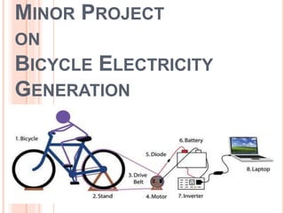
1. We have taken a bicycle.
2. We have removed the last tyre and the tube of it
and in place of that we have fitted a pulley there.
10. 3. We have prepared a frame with dimensions of 20” x 20” of M.S. bars. The cutting of
the bar was done by power hexa.
11. 4. After the completion of the holding frame, the
bicycle is putted over the frame on to the axles
of the last wheel.
5. The belt is fitted over the wheel and the
accumulator.
6. The wire of the accumulator is connected with
the inverter by connecting the diode in the
middle of the connections.
7. The battery is attached to the inverter, which
store the energy produced by the rotation of
belt.
8. A electrical device is connected to the battery
to desire the power produced
13. Using a few easily accessible parts, you can make a bicycle
generator that can power various electronic appliances, such
as laptops and batteries!
Materials needed:
Bicycle Stand
Bicycle frame
24V DC scooter motor
DC-DC battery charger
A car battery, or something similar
DC-AC inverter
Wires for electrical connections and various bike parts and
tools.
A multi-meter might be useful to check various voltage
differentials between different objects.
The specific hardware we used:
Motor: 24V 300W Scooter Motor
Battery: 12V 18 amp-hr lead-acid battery model 7448k51
Charger: Thunder 620 battery charger- 300 Watt 20 Amp
Inverter: 400 Watt inverter Model 6987k22
14. STEP 1: BIKE STAND
First you need something to hold
your bike. You can either build your
own bike stand or buy them. We
used a bought stand for the back
and made our own for the front.
These stands are especially nice for
the back wheel because some of
them are adjustable from side to
side (right and left to the rider). This
variation makes aligning the
connection to the motor easier.
15. STEP 2: BICYCLE FRAME
Any bike frame will do, as
long as the pedals spin the
chain.
This step is the most
hands-on and difficult of
the process. We
recommend that you use
the back wheel as the
connection to the motor.
However, if you want to
have a more efficient
connection, we also have
a more complex option.
16. STEP 3: BICYCLE TO MOTOR
Here we again face a choice: we
can use the back wheel to spin the
motor, or you can go more directly
from the chain to the motor. Using
the back wheel wastes some energy
in friction and spinning a mass. But
getting the correct gear ratio for the
chain-to-motor strategy proves
difficult.
This step is the most hands-on and
difficult of the process. We
recommend that you use the back
wheel as the connection to the
motor. However, if you want to have
a more efficient connection, we also
have a more complex option.
17. WHY WE NEED A MOTOR:
The motor converts movement of your legs into DC
electricity.
Choosing a Motor: A stepper motor, car alternator,
or an electric scooter motor will all work. We used a
scooter motor. The motor produced voltage
proportional to its RPM . The motor produces
current based on the load attached.
For reference, a mountain bike tire going at 20 mph
spins at 250 RPM. Additional RPMs for the motor
come from the ratio of the wheel size to the
frictional cylinder on the motor.
18. STEP 4: BACK WHEEL OPTION
Making a bike generator using the back wheel is the
more common method. Find a motor that can mount a
cylinder that can grip well to the back wheel of the bike.
Using a hinge and various plates of aluminum, you can
construct an adjustable mount for the motor that will
allow you to vary the amount of contact between the
cylinder and the wheel. You attach the motor to the
upper plate, and adjust the position or angle of the plate
with a bolt or screw.
The back wheel option will give you all the RPM that you
need-the gear ratio between the wheel and the cylinder
in the back creates plenty of RPM and thus more than
enough voltage.
Additional RPMs for the motor come from the ratio of the
wheel size to the frictional cylinder on the motor.
19. STEP 5: V-BELT TO MOTOR OPTION
To attach the belt of the bike directly to the motor,
you will need a few changes of gear ratio.
Adjust the belt from the back wheel to the motor
Even with the belt, you will probably still only be
producing 3-6 volts but the pedaling will be very
easy. The scooter motor produces voltage
proportional to the RPMs (revolutions per minute) of
the motor shaft.
20. STEP 6: MOTOR TO CHARGER
Why we need a charger:
To charge, batteries need a voltage slightly higher
than their output voltage. Putting in too high a voltage
can damage the internal circuitry of the battery,
reducing its lifetime. Usually, circuits trickle a little bit
of current in a battery. But with a bicycle cranking out
watts, you want to put whole amps. Battery chargers
hold the voltage steady at the appropriate point, and
then increase the current allowing higher than normal
transmission of power.
Picking a Charger:
Remember that the voltage of your motor will be
varying with the speed of your pedaling. The charger
we used takes anywhere from 12- 24V. Though
chargers may brag outputs of 10s to 20s of amps,
batteries cannot stand such current. For example, the
battery we used has a maximum charging current of
5.4 amps. Check that the current of your charger
matches the limit of your battery.
21. Connecting:
With a multimeter, measure the voltage coming out of your
motor. Connect the positive output of the motor to the positive
input of the charger and vice versa with the ground wire.
Depending on the direction you spin the motor, the positive
wire may not be the red wire; the motor works both directions
but gives inverse voltage. If you can adjust the output current.
As you may expect, larger current charges the battery faster
but makes pedaling harder.
A word of warning: Do not overload the charger! Depending
on your gear system, it can be very easy to put out more than
24V. Doing so will break your charger. If you will not be the
only one using the system, consider adding zener diodes in
case of excess voltage.
22. STEP 7: CHARGER TO BATTERY
Why we need a Battery:
Charging your laptop could take a few hours, but
you probably do not want to be on your stationary
bike for that long. The battery holds your generated
watts to be dowled out on an as-need basis.
Choosing a Battery:
If a traditional car batterys are called lead-acid
batteries; You do not want lead-acid dripping from
you battery if you tip it over. Furthermore, we heard
that if a car battery is tipped over, it can short circuit
and explode. .
Marine batteries or sealed batteries can withstand
the tipping of a tumultuous world. Make sure your
battery is rechargeable. And finally, choose the
capacity of the battery to match your needs. We
chose a 18 Amp-h battery because it holds about
three laptops worth of energy.
23. Connecting:
Use the same caution as you do when jumping your car.
Connect the positive terminal first for added safety. The
voltage across your battery will be different when you are
charging, when it is sitting, and when it is discharging; they
will be about 14V, 12.5V, and 11 V respectively. The spec
sheet for our battery warned to stop charging when the
voltage reached 14.4 V. Check your battery’s spec sheet for
its max voltage point.
Most capacitors suitable for creating a single bike generator
have been designed for 12v car audio systems and come with
a safety cut out to protect against over voltage linked to rpm
for a pm motor. Another reason why car audio capacitors are a
good buy as they often come with their own built in volt meter.
24. AN INVERTER
If you are wishing to use AC mains powered appliances you will need
to purchase an inverter. There are 2 types of inverters. A pure sine
wave inverter creates a smooth AC output. A quasi sine makes a
square wave. Some devices may not work with a quasi sine.
Inverters are designed to work with batteries so they usually work
with voltages between 9 and 14volts.
CABLES AND CONNECTORS
We used 30A Anderson Connectors when connecting the bikes into
either a multiple or single bike system. The connectors hold a good
connection but are also designed to ‘pop’ easily, if your foot trips on a
cable for example, so you don’t damage any soldering. It’s a good
idea to get fairly chunky cable for your ‘Bike Power Cables’,
especially if the lengths start to get long. You want to avoid voltage
drop as it’s a waste of energy.
The smaller the cable diameter, the more it will heat up, the more
energy you loose. It’s also possible to knock out 25A on a bike for
bursts, so your cable should be able to handle that. We managed to
get some paired (black & red wires in the same sheath) 4mm core
speaker cable, which meant the cable kept nice and neat
25. STEP 8: BATTERY TO INVERTER
Why we need an inverter:
The AC inverter converts the DC voltage from the battery into AC
voltage, which is what comes out of most electrical wall sockets.
You’ll often see inverters on a small scale in car adaptors, where they
take the power from the cigarette lighter (which is hooked up to the
car’s battery). Most general purpose AC inverters are Modified Sine
Wave inverters. If you want to know more about how these inverters
work, here is a good reference source.
Choosing an inverter:
When shopping for inverters, you want to look for a few features.
First, make sure that the output AC voltage is at the level of wall
plugs. Wall sockets usually put out about 120V, but it isn’t absolutely
necessary to have your voltage match that; anything from 110-130
Volts AC will be fine. Be sure that the frequency of the output is at 60
Hz, which is standard in the India.