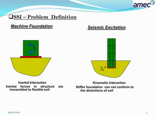
This document discusses soil-structure interaction and foundation vibrations. It begins with an introduction to soil-structure interaction, noting that the response of the soil influences the motion of the structure and vice versa. It then discusses how soil-structure interaction can alter the natural frequency and add damping to a structural system. The document outlines different effects of soil-structure interaction and how it is an important consideration in seismic analysis and design. It also discusses impedance functions, compliance functions, and modeling of machine foundation vibrations.

![SOIL STRUCTURE INTERACTION (SSI):
Definition:
The process in which the response of the soil influences the motion of the structure
and the motion of the structure influences the response of the soil is termed as SSI.
In this case neither the structural displacements nor the ground displacements are
independent from each other.
Traditional Structural Engineering methods disregard SSI effects, which is
acceptable only for Light structures on relatively stiff soil (low rise structures
and simple rigid retaining walls).
SSI effects become prominent and must be regarded for structures where P-δ
effects play a significant role,structures with massive or deep seated
foundations,slender tall structures and structures supported on a very soft
soils with average shear velocity less than 100 m/s.[Euro Code 8].
Modern Seismic Design Codes such as Standard Specifications for Concrete
Structures: Seismic Performance Verification JSCE 2005 (Japan Society of Civil
Engineers) highlight that the response analysis should take into account the whole
structural system ( superstructure + foundation + soil ).
29/02/2012 3](https://image.slidesharecdn.com/soil-structureinteractionamecpresentation-final-120229222007-phpapp01/85/Soil-structure-interaction-amec-presentation-final-3-320.jpg)
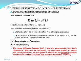
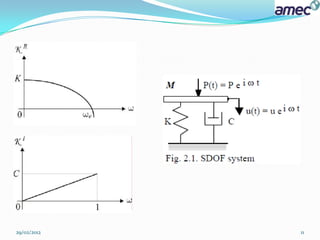
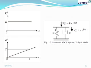
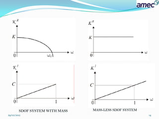
![ SDOF with mass(Sup-structure & Foundation ):
M ü +C ù +K u = P(t)
K1 = KR + iKI
= [(K –Mω2)] +iC ω
KSTR = - Mω2
KFDN = K +iC ω.
29/02/2012 10](https://image.slidesharecdn.com/soil-structureinteractionamecpresentation-final-120229222007-phpapp01/85/Soil-structure-interaction-amec-presentation-final-10-320.jpg)
![ Mass-less SDOF system (SOIL):
K2 = K+ iC ω .
KR = K .
KI = C ω.
It is important to note that Impedance functions for the soil are always
derived from the massless foundation model.
K2 : can be obtained by setting M=0 in K1.
The impedance function of the soil is equal to Foundation impedance
component for SDOF system with mass [ KFDN ].
29/02/2012 12](https://image.slidesharecdn.com/soil-structureinteractionamecpresentation-final-120229222007-phpapp01/85/Soil-structure-interaction-amec-presentation-final-12-320.jpg)
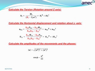
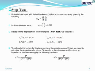
![Step One :
Dimensionless Circular frequency is given by the following equation:
= (2*PI*16.71*1)/[SQR(45000/2)] = 0.7
Comments:
- In 2D structures only three DOF are considered:
1- Vertical displacement along Z-axis.
2- Horizontal displacement along X- axis.
3- Rotation around horizontal Y- axis.
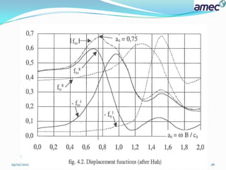
For our example, we do not have vertical Oscillation of the center of gravity,
therefore the following Displacement functions developed by HUH (1986) [ for strip
foundation without embedment resting on horizontal layer, , ,
H/B=2 ] will not include the vertical displacement functions.
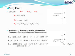
For foundations that are not embedded, the rotation around Y-axis and the
translation along X-axis are uncoupled. In General Cases these two modes are
always coupled.
29/02/2012 25](https://image.slidesharecdn.com/soil-structureinteractionamecpresentation-final-120229222007-phpapp01/85/Soil-structure-interaction-amec-presentation-final-25-320.jpg)
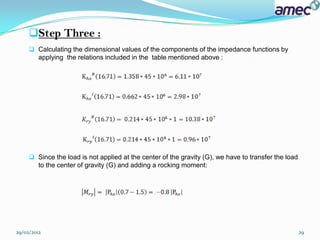
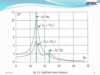
![ The complete curves are given on the following figures. From these curves we find
that the maximum amplitudes of the displacement and the rotation are obtained for
14.3 HZ [ first mode ].
the natural (Eigen) frequency of the soil layer without footing which is 18.7 HZ :
The dynamic effect of the soil structure interaction is clear.
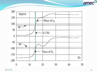
From the second figure we see that the phases are close to (+/-)90 degrees at the
first maximum of the amplitude.
29/02/2012 32](https://image.slidesharecdn.com/soil-structureinteractionamecpresentation-final-120229222007-phpapp01/85/Soil-structure-interaction-amec-presentation-final-32-320.jpg)


![Geotechnical Engineering-II [Lec #15 & 16: Schmertmann Method]](https://cdn.slidesharecdn.com/ss_thumbnails/15-181020124920-thumbnail.jpg?width=640&height=640&fit=bounds)


![Geotechnical Engineering-II [Lec #9+10: Westergaard Theory]](https://cdn.slidesharecdn.com/ss_thumbnails/9-181020124827-thumbnail.jpg?width=640&height=640&fit=bounds)


