UMN_Dynamic_Foundations dynamic and sensitive equipments.pdf
1.
Foundations for Dynamicand
Sensitive Equipment
University of Minnesota - Structures Seminar
October 30, 2015
Carl Nelson, Ph.D., P.E.
Tony Baxter, P.E.
2.
2
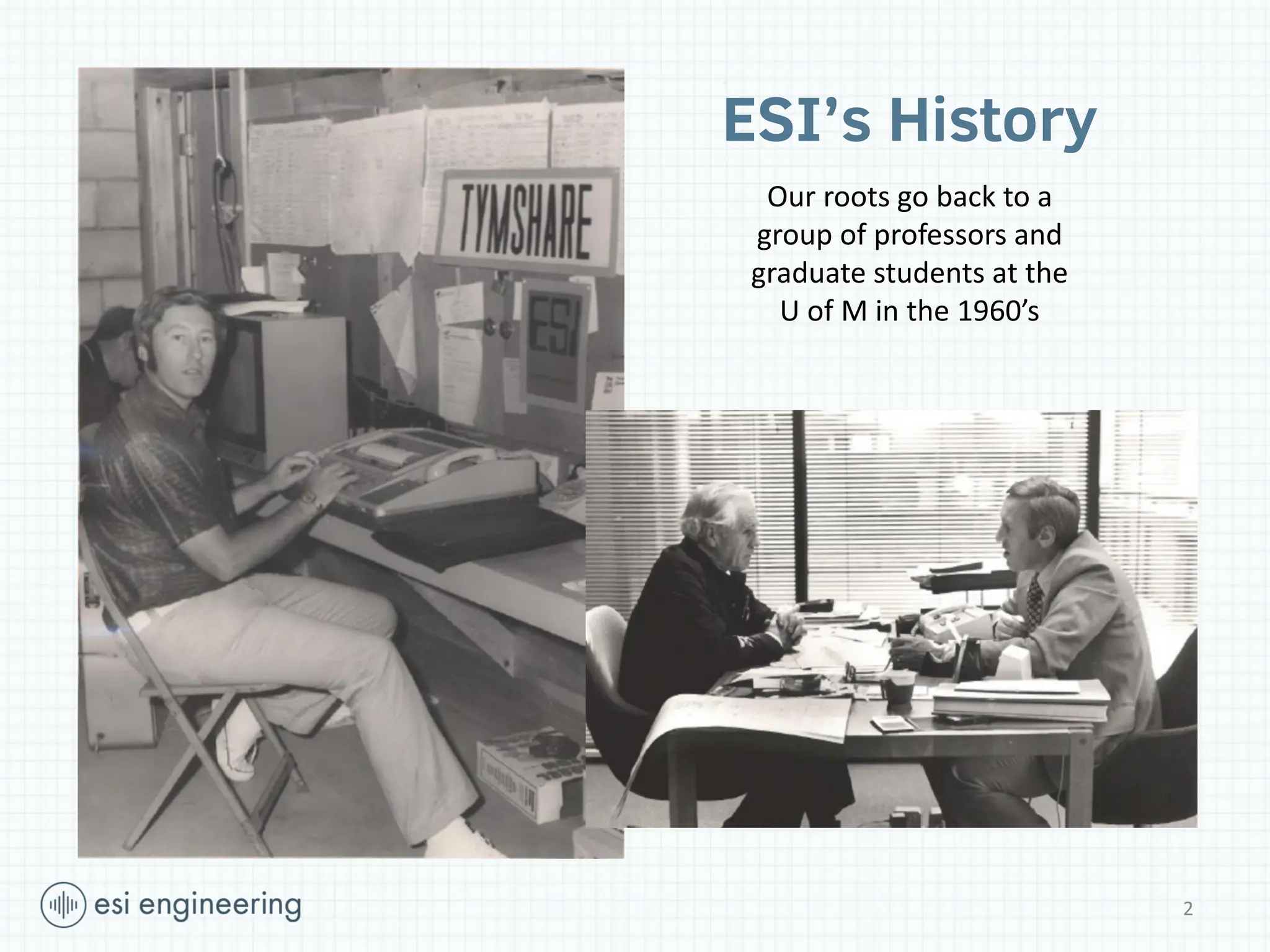
ESI’s History
Our rootsgo back to a
group of professors and
graduate students at the
U of M in the 1960’s
3.
3
Who We AreToday!
Minnesota based consulting engineering firm since 1970
Provide specialized engineering services
Specialists in high force/shock, vibration and noise control
From small medical devices and consumer products to sensitive buildings and large
industrial facilities, ESI helps clients with advanced analysis and design. Our professional
engineering services are focused in the areas of structural dynamics and design,
vibration control, noise and acoustics, and monitoring.
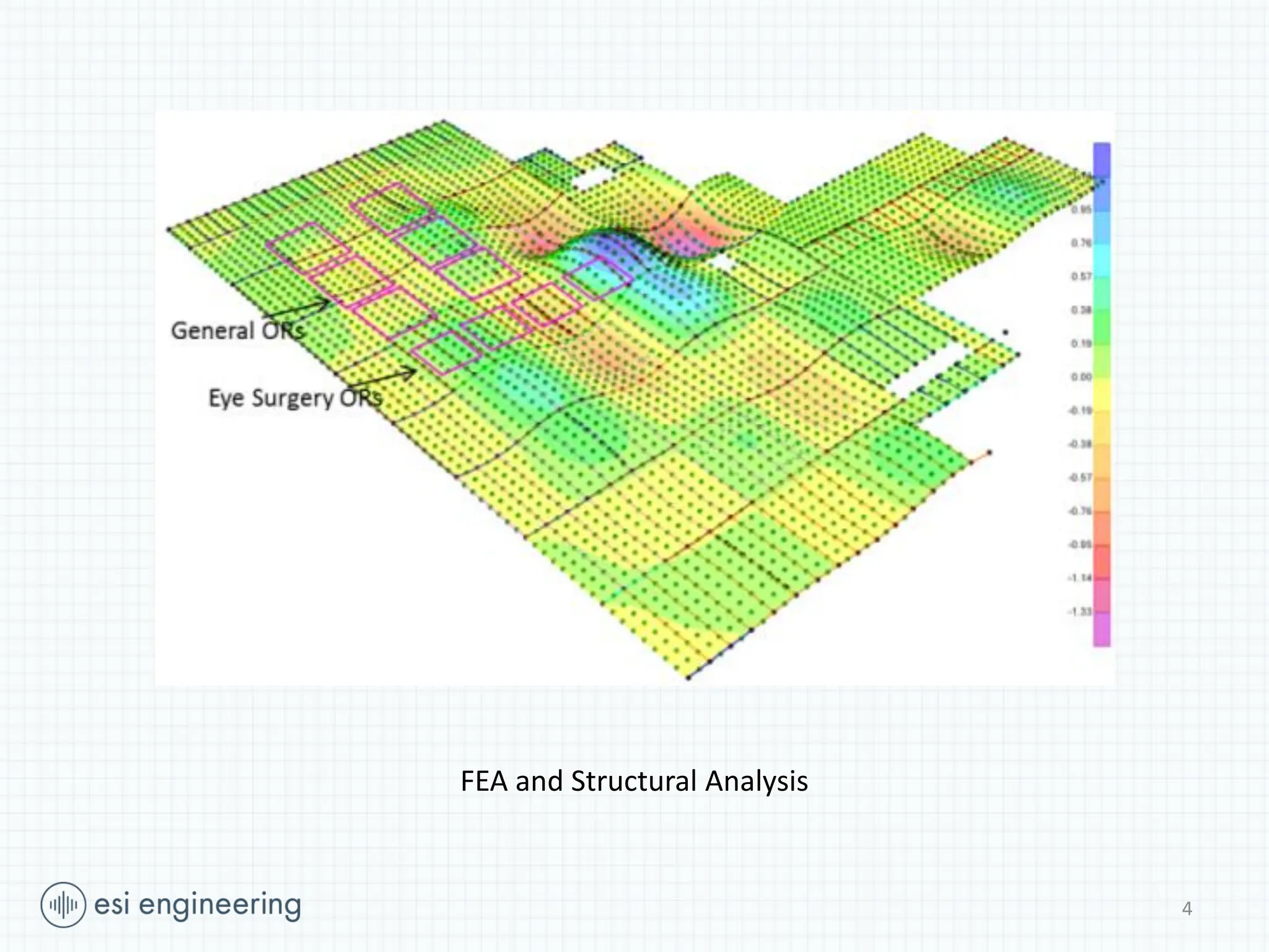
Recent Projects atU of M
Rec Center Expansion
Cancer and Cardio Research Building
Physics and Nanotechnology Cleanroom
Northrop Balconies
SE corner of clean
room floor
soil
drilled piers
(soil not shown)
N
8
9.
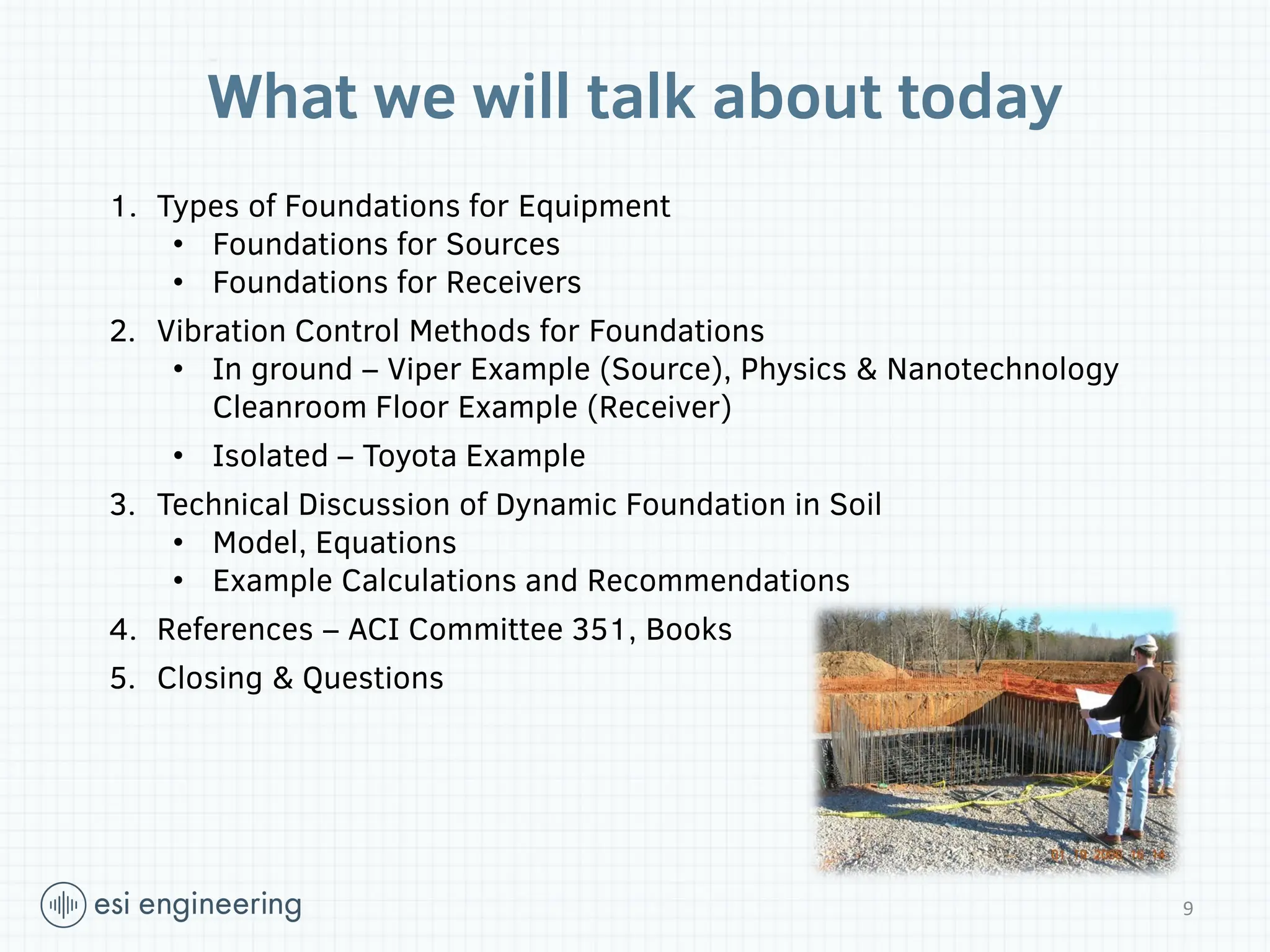
What we willtalk about today
1. Types of Foundations for Equipment
• Foundations for Sources
• Foundations for Receivers
2. Vibration Control Methods for Foundations
• In ground – Viper Example (Source), Physics & Nanotechnology
Cleanroom Floor Example (Receiver)
• Isolated – Toyota Example
3. Technical Discussion of Dynamic Foundation in Soil
• Model, Equations
• Example Calculations and Recommendations
4. References – ACI Committee 351, Books
5. Closing & Questions
9
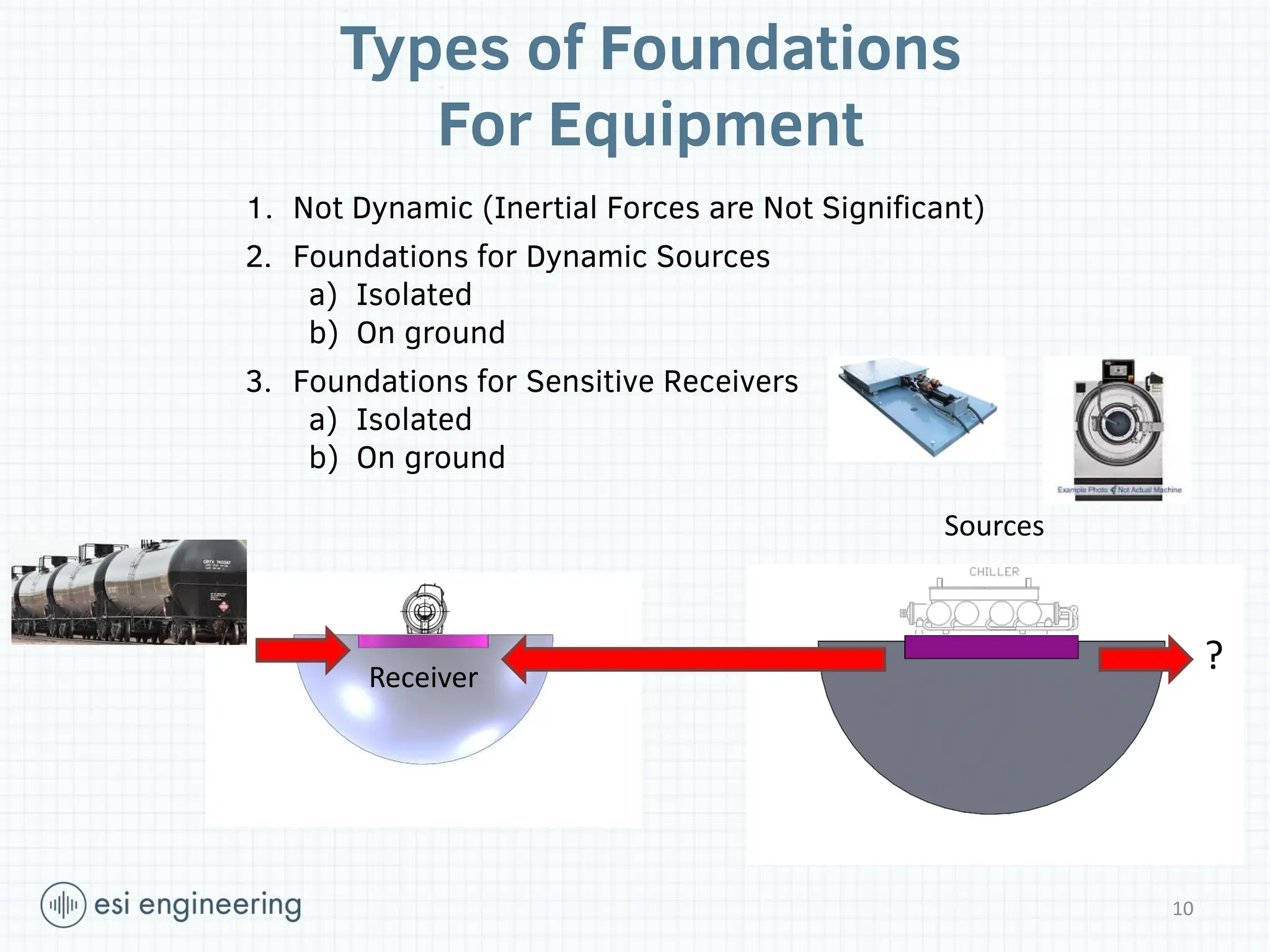
10.
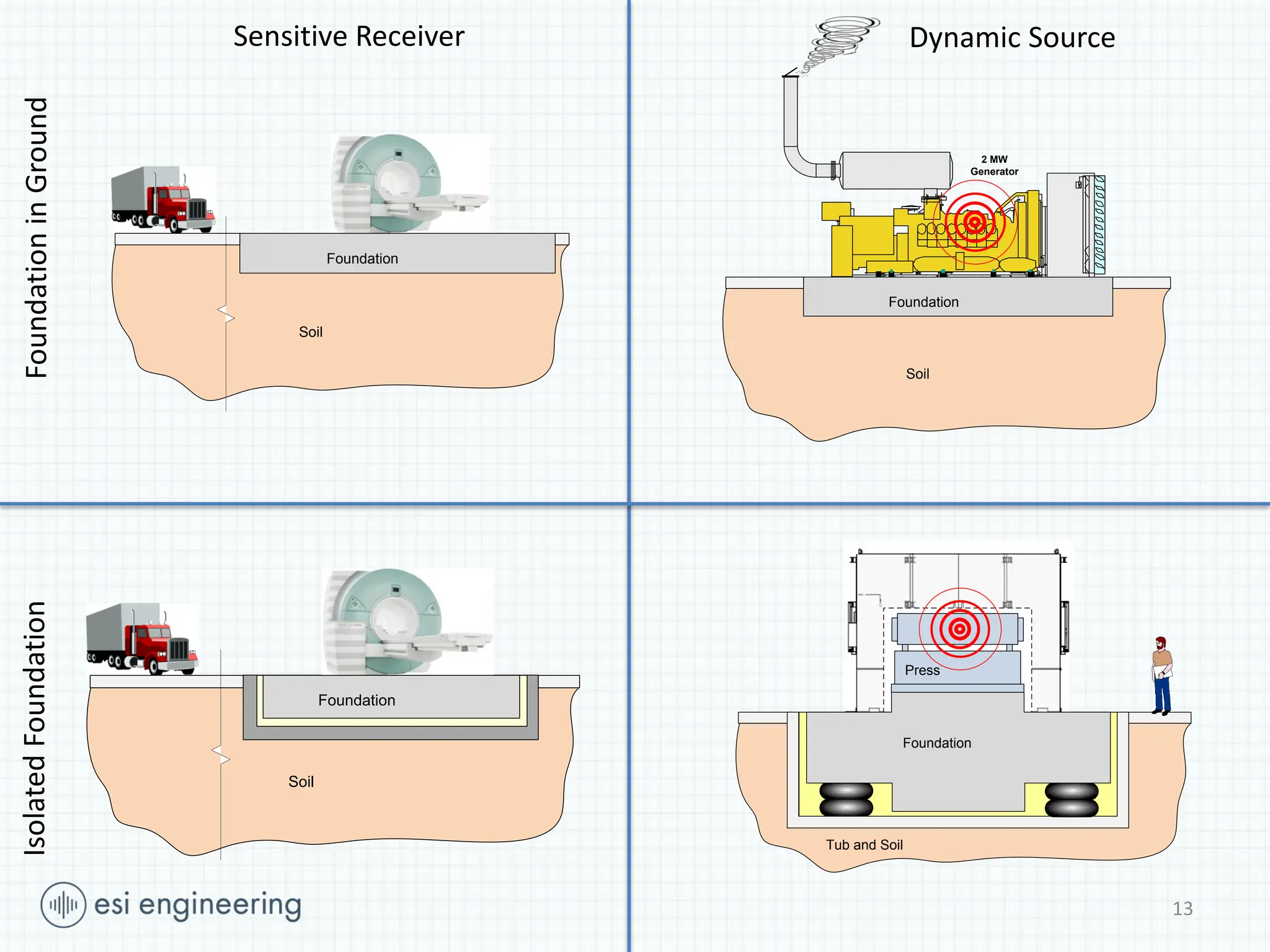
Types of Foundations
ForEquipment
1. Not Dynamic (Inertial Forces are Not Significant)
2. Foundations for Dynamic Sources
a) Isolated
b) On ground
3. Foundations for Sensitive Receivers
a) Isolated
b) On ground
Sources
Receiver
10
?
11.
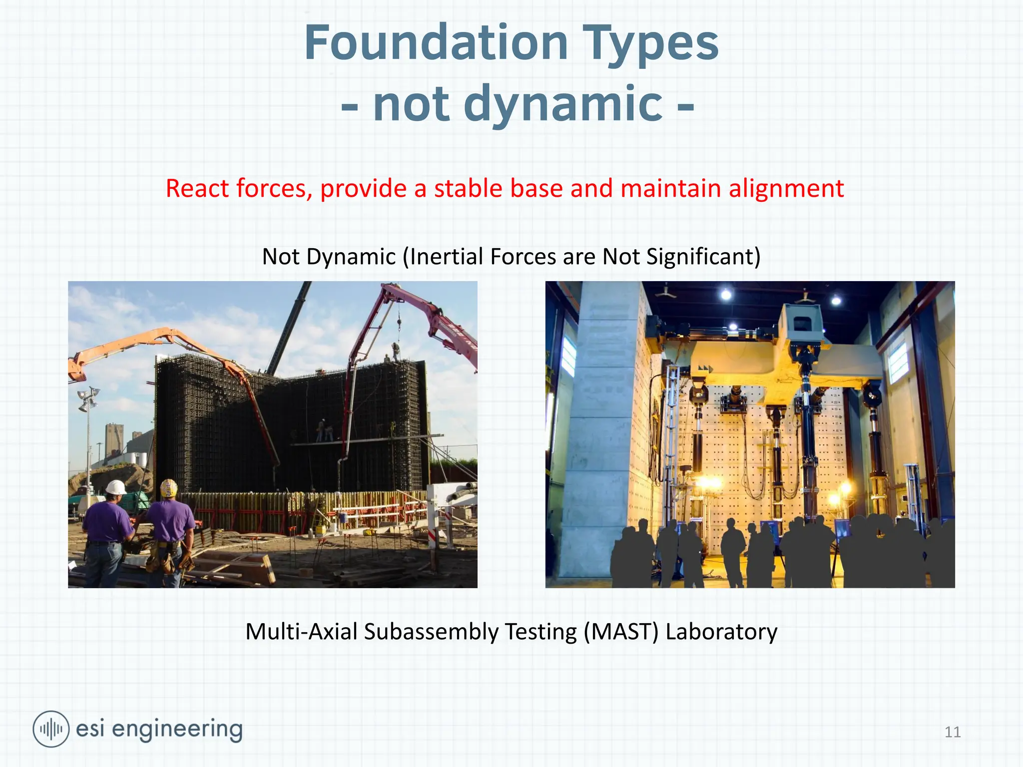
Foundation Types
- notdynamic -
Not Dynamic (Inertial Forces are Not Significant)
Multi-Axial Subassembly Testing (MAST) Laboratory
11
React forces, provide a stable base and maintain alignment
12.
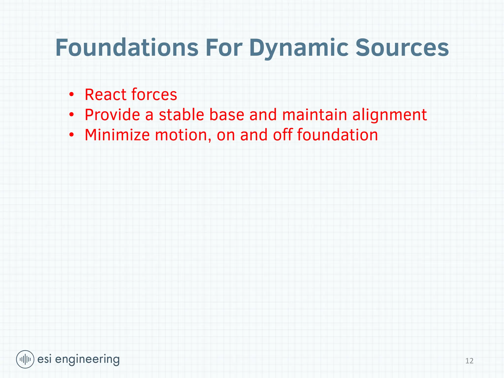
Foundations For DynamicSources
12
• React forces
• Provide a stable base and maintain alignment
• Minimize motion, on and off foundation
13.
13
Sensitive Receiver
K1 C1
M1
X1
Xg
Foundation
Soil
Foundationin Soil
2 MW
Generator
Foundation
Soil
K1 C1
M1
X1
Xg
Foundation
Soil
K2
M2
C2
X2
F2(
Press
Tub and Soil
Press and
foundation
Tub and soil
Foundation
Dynamic Source
Foundation
in
Ground
Isolated
Foundation
14.
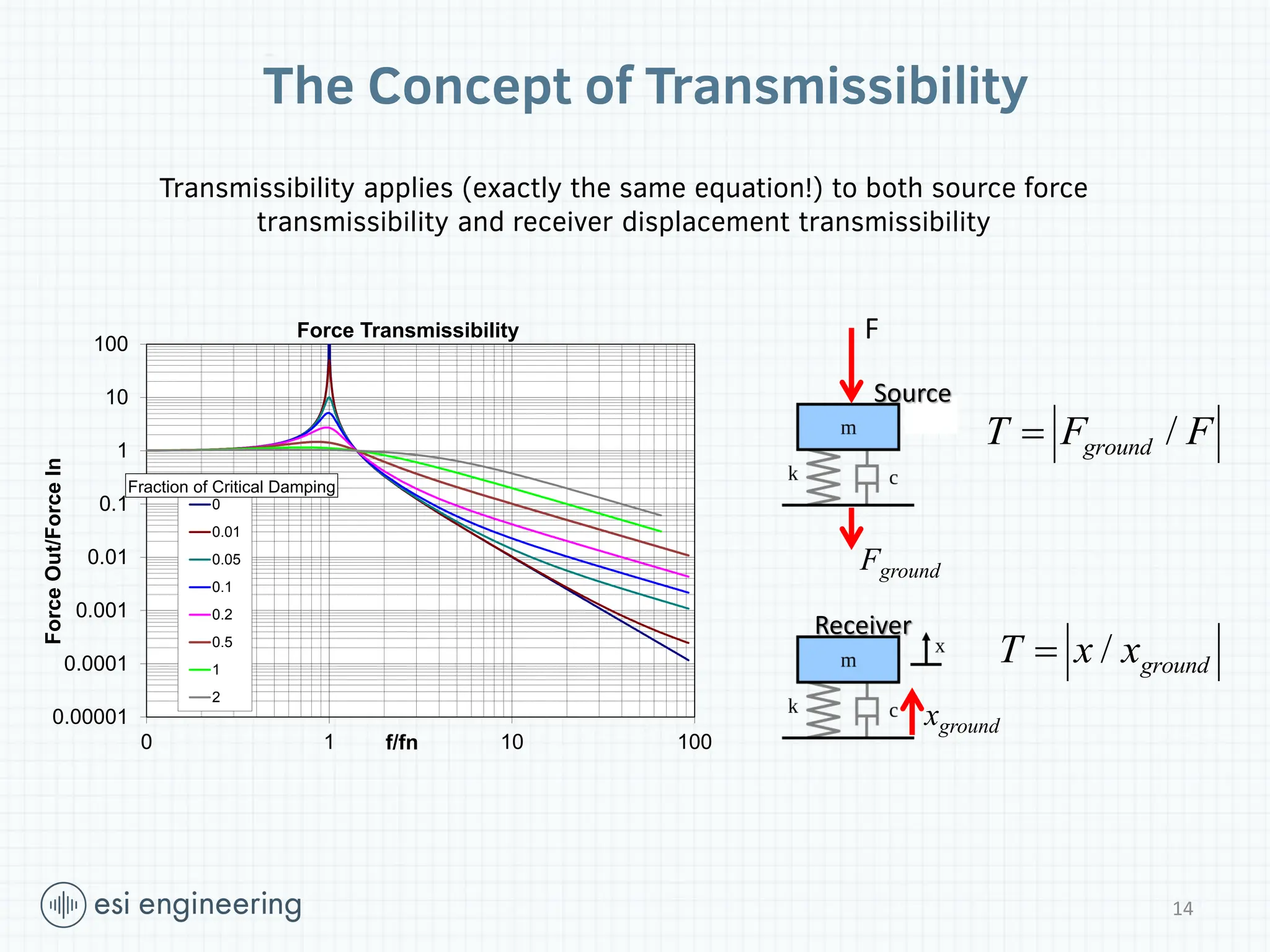
The Concept ofTransmissibility
0.00001
0.0001
0.001
0.01
0.1
1
10
100
0 1 10 100
Force
Out/Force
In
f/fn
Force Transmissibility
0
0.01
0.05
0.1
0.2
0.5
1
2
Fraction of Critical Damping
F
Fground
xground
/
ground
T F F
/ ground
T x x
Transmissibility applies (exactly the same equation!) to both source force
transmissibility and receiver displacement transmissibility
Receiver
Source
14
15.
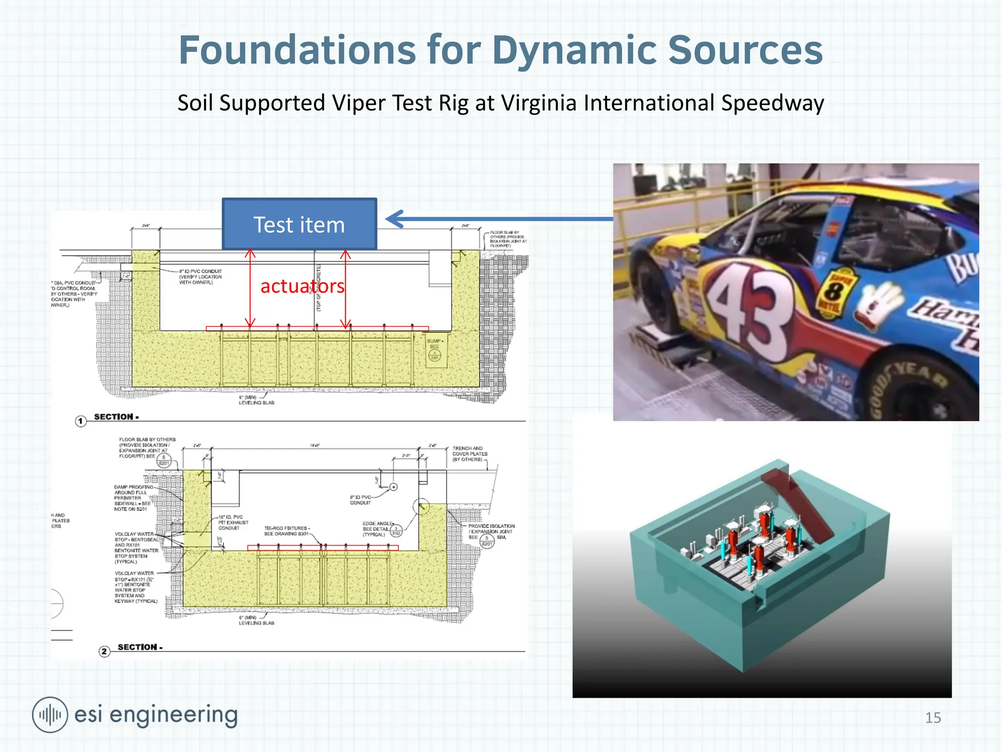
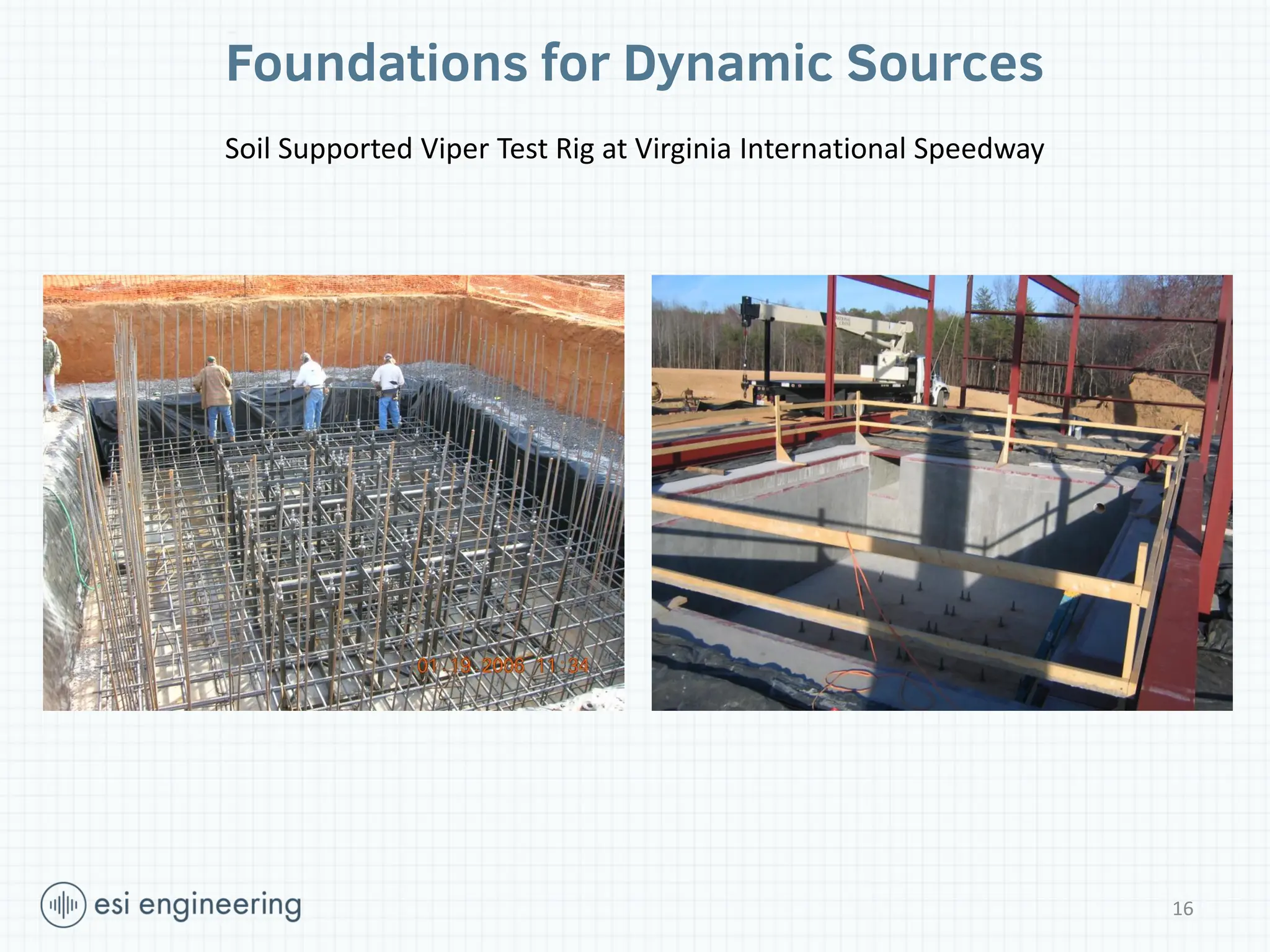
Foundations for DynamicSources
actuators
Test item
Soil Supported Viper Test Rig at Virginia International Speedway
15
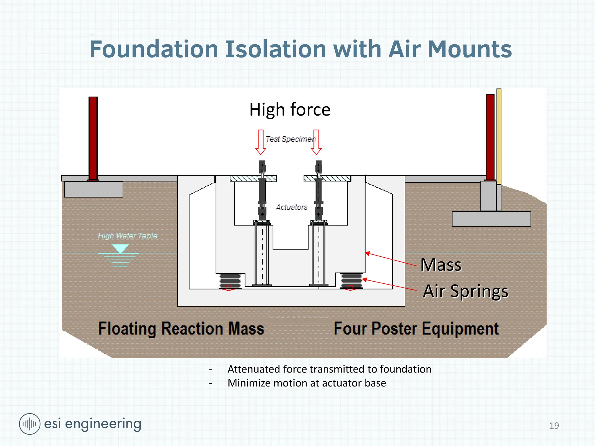
19
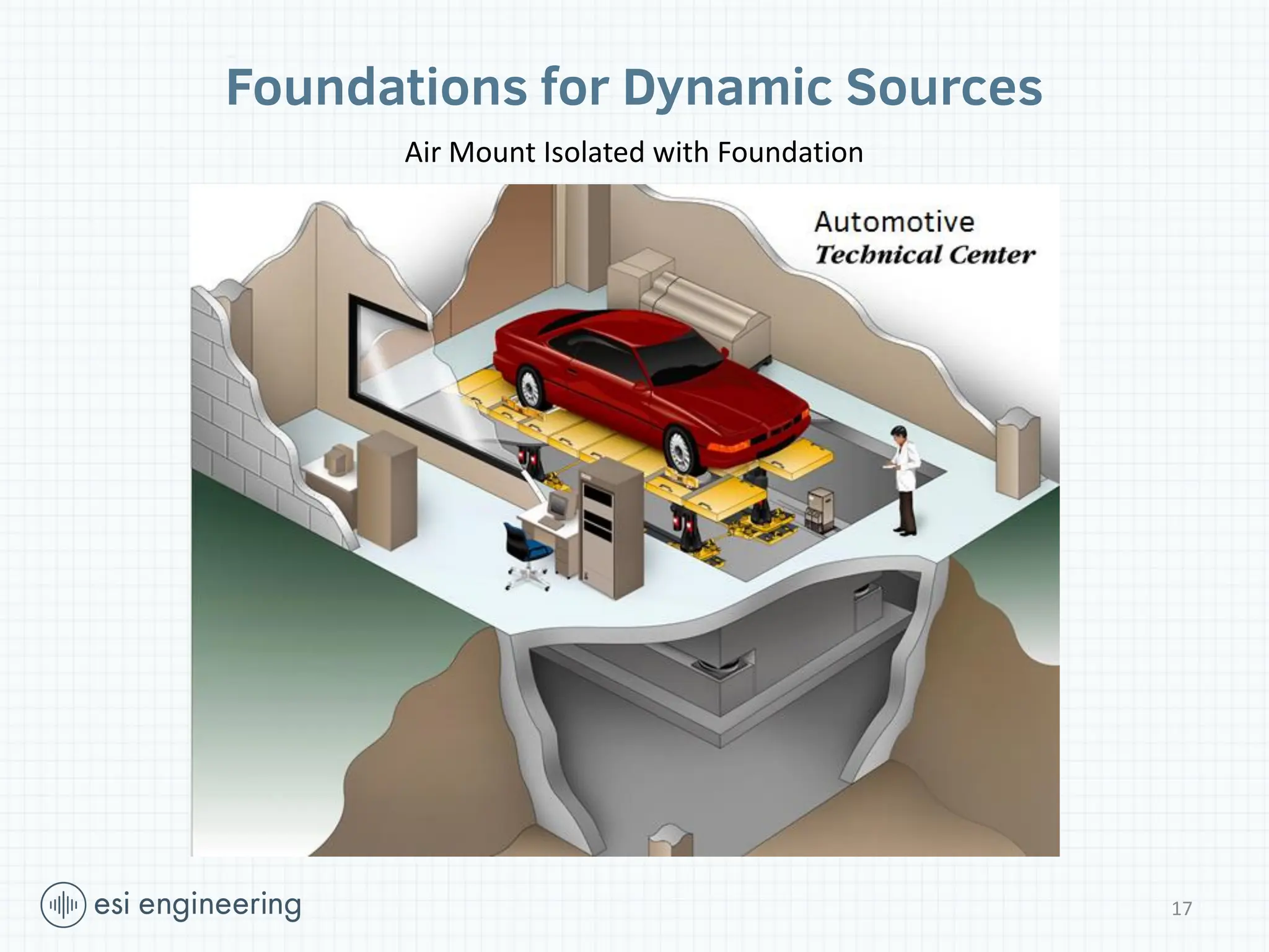
High force
Mass
Air Springs
-Attenuated force transmitted to foundation
- Minimize motion at actuator base
Foundation Isolation with Air Mounts
20.
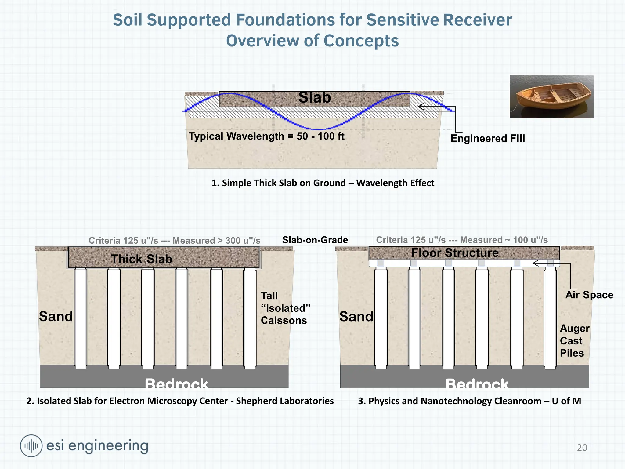
Soil Supported Foundationsfor Sensitive Receiver
Overview of Concepts
20
Engineered Fill
Slab
1. Simple Thick Slab on Ground – Wavelength Effect
2. Isolated Slab for Electron Microscopy Center - Shepherd Laboratories
Bedrock
Sand
Thick Slab
Criteria 125 u"/s --- Measured > 300 u"/s
Tall
“Isolated”
Caissons
Slab-on-Grade
Typical Wavelength = 50 - 100 ft
Bedrock
Sand
Auger
Cast
Piles
3. Physics and Nanotechnology Cleanroom – U of M
Air Space
Floor Structure
Criteria 125 u"/s --- Measured ~ 100 u"/s
21.
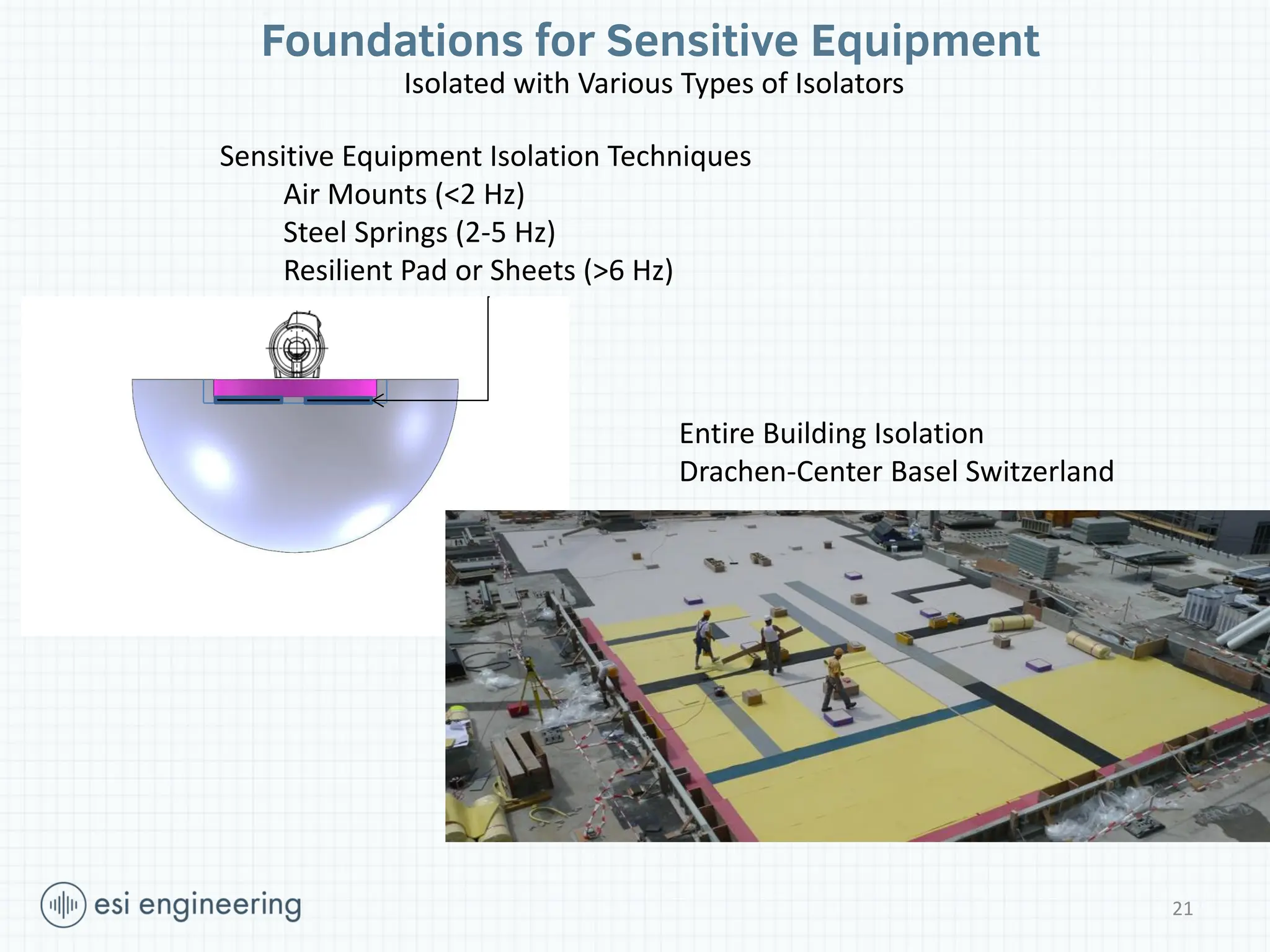
Foundations for SensitiveEquipment
Isolated with Various Types of Isolators
Sensitive Equipment Isolation Techniques
Air Mounts (<2 Hz)
Steel Springs (2-5 Hz)
Resilient Pad or Sheets (>6 Hz)
Entire Building Isolation
Drachen-Center Basel Switzerland
21
22.
22
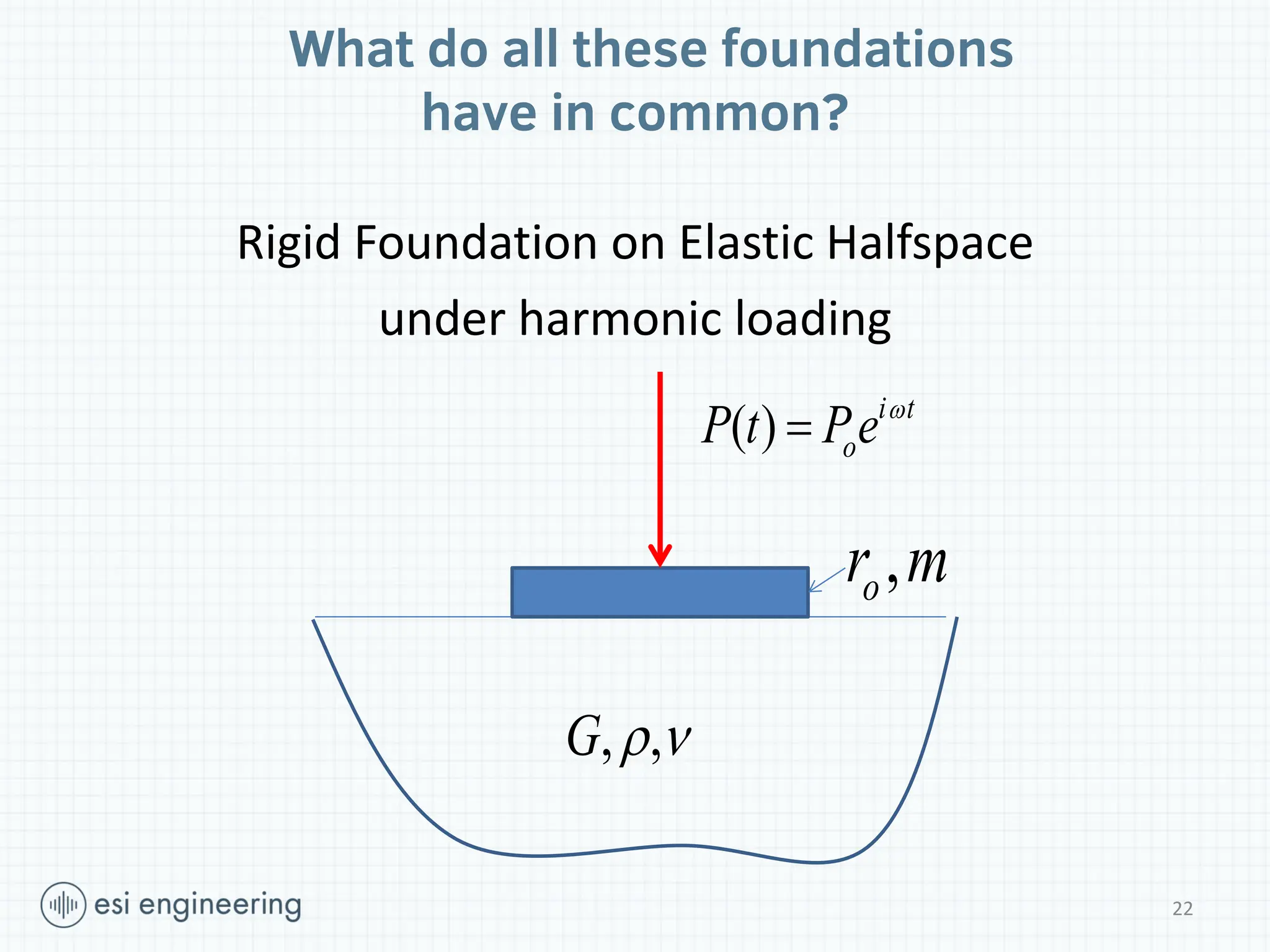
Rigid Foundation onElastic Halfspace
under harmonic loading
, ,
G
,
o
r m
( ) i t
o
P t Pe
What do all these foundations
have in common?
23.
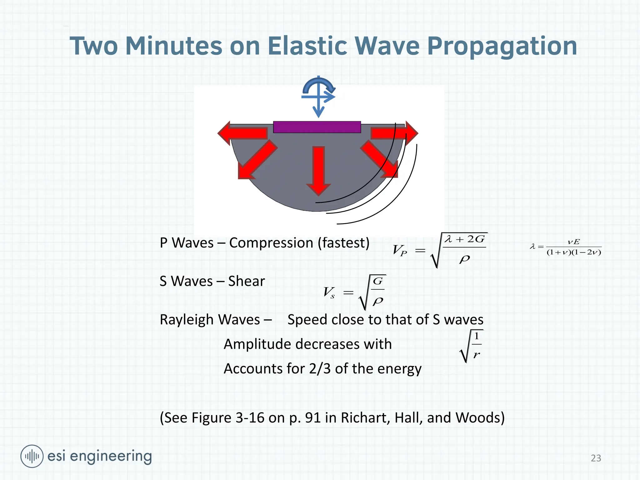
Two Minutes onElastic Wave Propagation
P Waves – Compression (fastest)
S Waves – Shear
Rayleigh Waves – Speed close to that of S waves
Amplitude decreases with
Accounts for 2/3 of the energy
(See Figure 3-16 on p. 91 in Richart, Hall, and Woods)
s
G
V
2
P
G
V
1
r
(1 )(1 2 )
E
23
24.
24
24
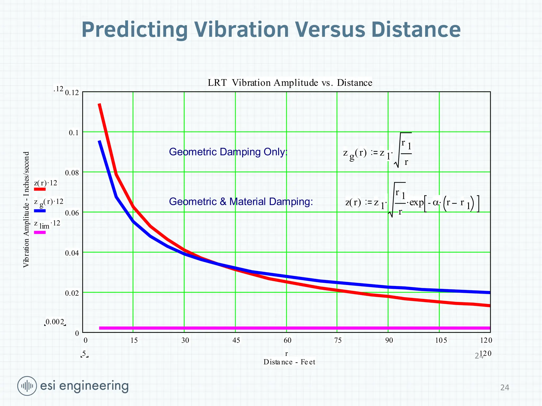
Predicting Vibration VersusDistance
0 15 30 45 60 75 90 105 120
0
0.02
0.04
0.06
0.08
0.1
0.12
LRT Vibration Amplitude vs. Distance
Dista nce - Fe et
Vibration
Amplitude
-
I
nches/second
.12
0.002
.
z( )
r 12
.
z g( )
r 12
.
z lim 12
120
5 r
Geometric Damping Only: z g( )
r .
z 1
r 1
r
Geometric & Material Damping: z( )
r .
.
z 1
r 1
r
exp .
r r 1
25.
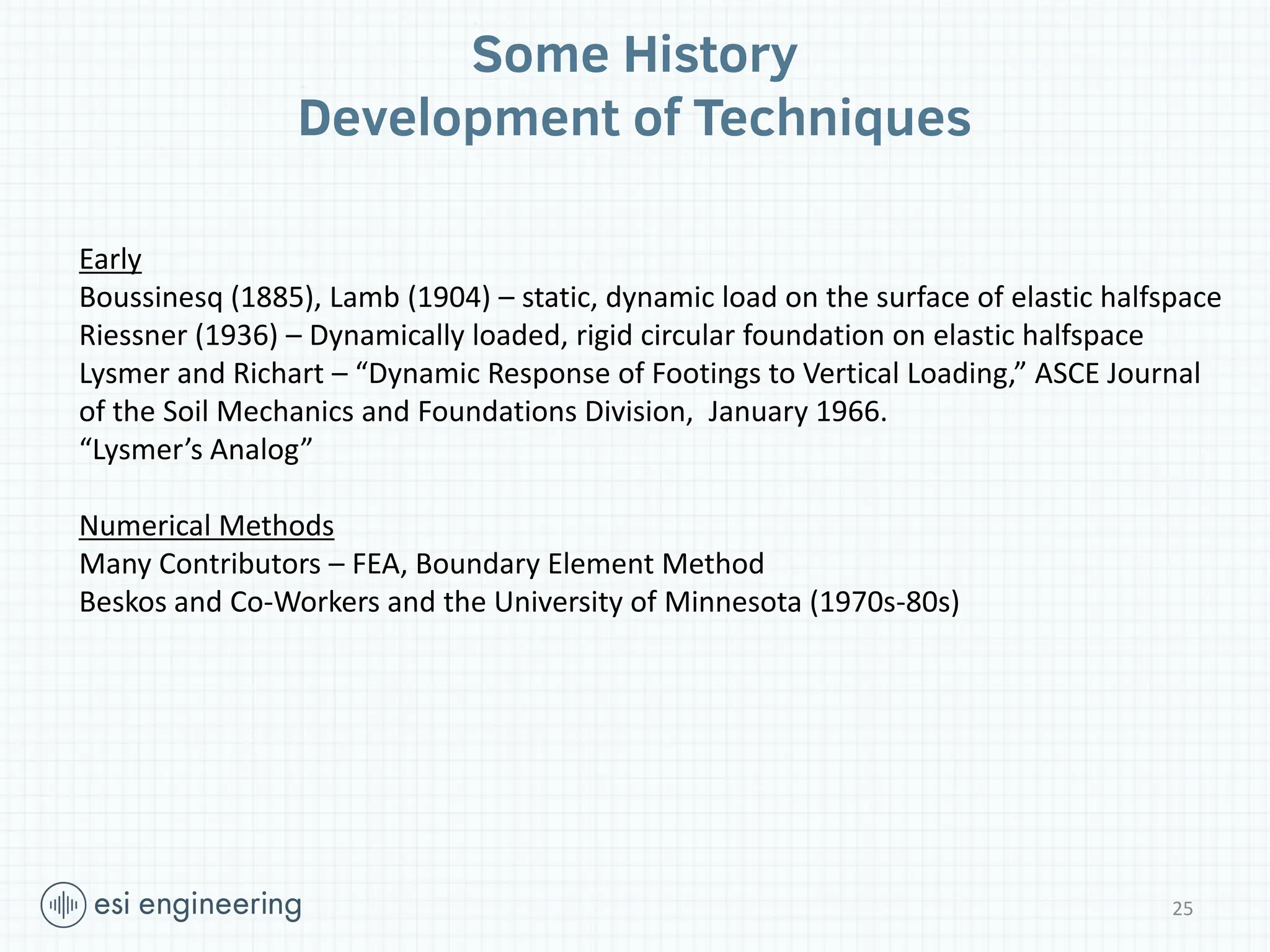
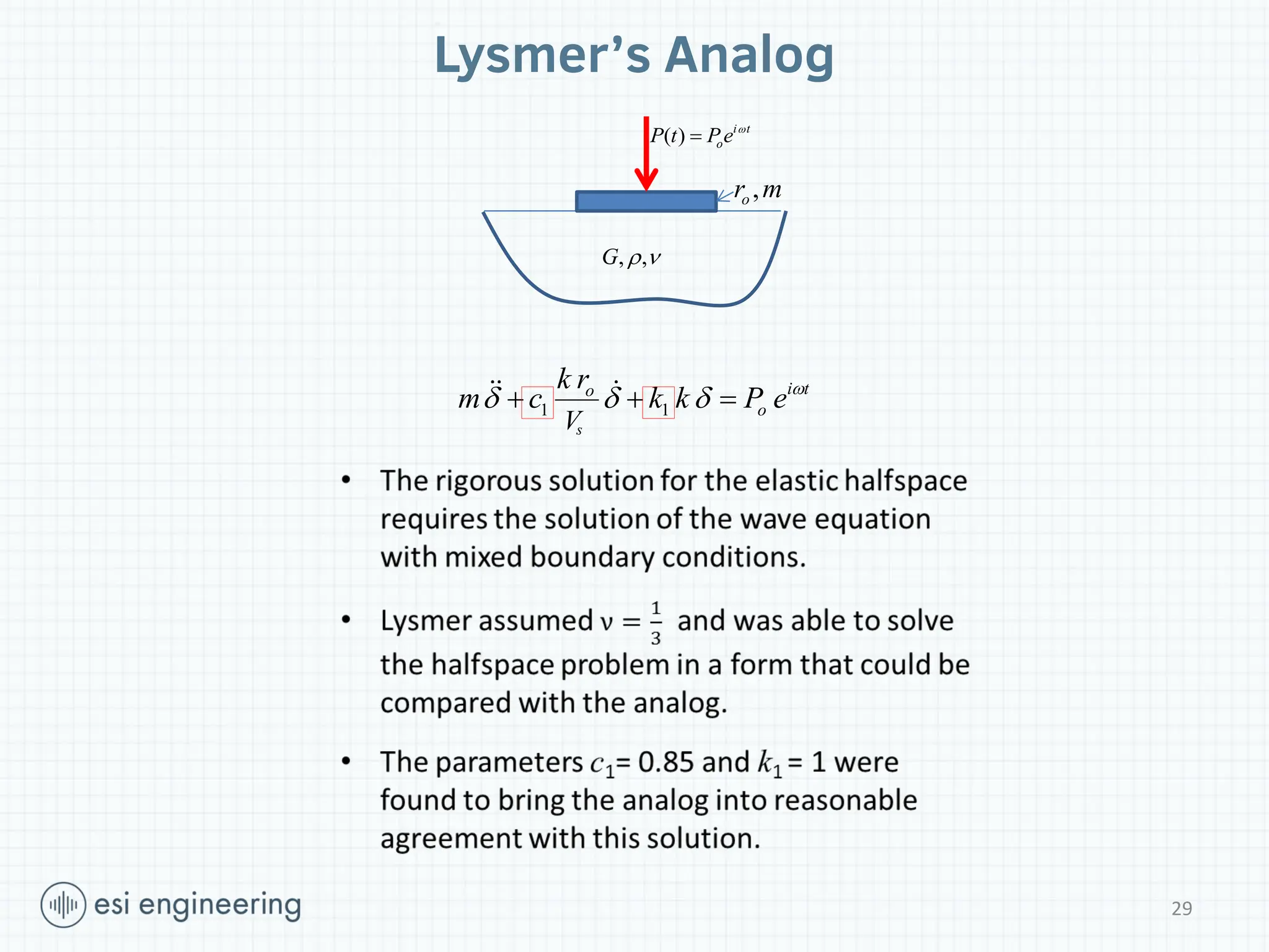
Early
Boussinesq (1885), Lamb(1904) – static, dynamic load on the surface of elastic halfspace
Riessner (1936) – Dynamically loaded, rigid circular foundation on elastic halfspace
Lysmer and Richart – “Dynamic Response of Footings to Vertical Loading,” ASCE Journal
of the Soil Mechanics and Foundations Division, January 1966.
“Lysmer’s Analog”
Numerical Methods
Many Contributors – FEA, Boundary Element Method
Beskos and Co-Workers and the University of Minnesota (1970s-80s)
Some History
Development of Techniques
25
26.
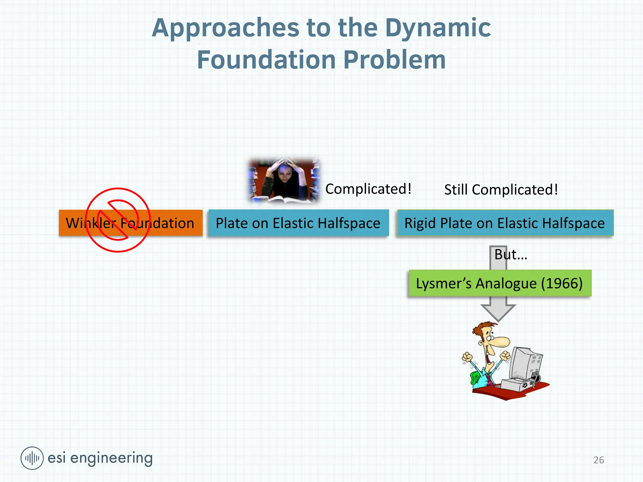
Winkler Foundation Plateon Elastic Halfspace Rigid Plate on Elastic Halfspace
Lysmer’s Analogue (1966)
Complicated! Still Complicated!
But…
Approaches to the Dynamic
Foundation Problem
26
27.
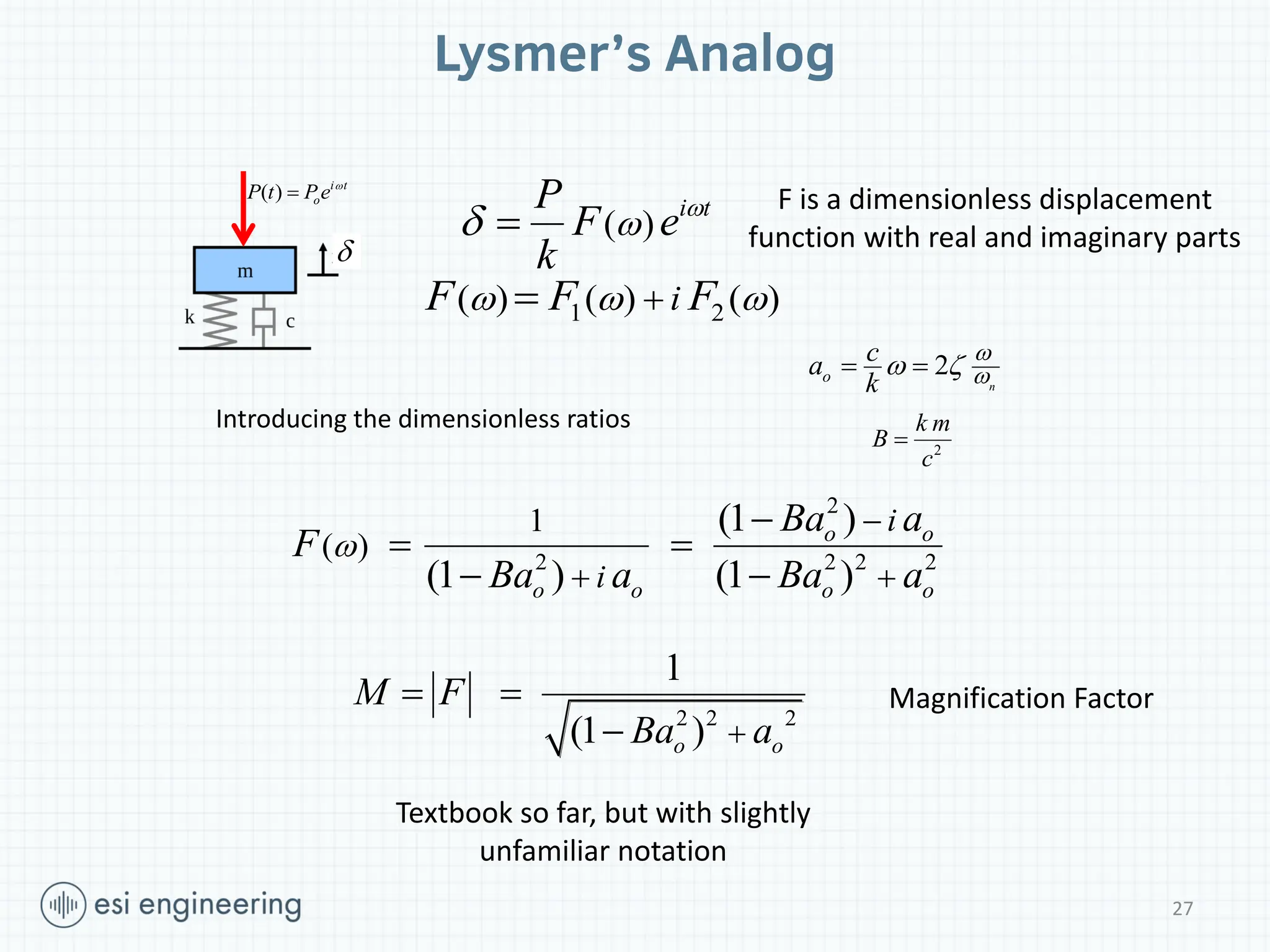
Lysmer’s Analog
( )
it
P
F e
k
1 2
( ) ( ) ( )
i
F F F
F is a dimensionless displacement
function with real and imaginary parts
2
2 2 2 2
1
( )
(1 )
(1 ) (1 )
o o
o o o o
i
i
Ba a
F
Ba a Ba a
2 2 2
1
(1 )
o o
M F
Ba a
Textbook so far, but with slightly
unfamiliar notation
( ) i t
o
P t Pe
Magnification Factor
2
n
o
c
a
k
2
k m
B
c
Introducing the dimensionless ratios
27
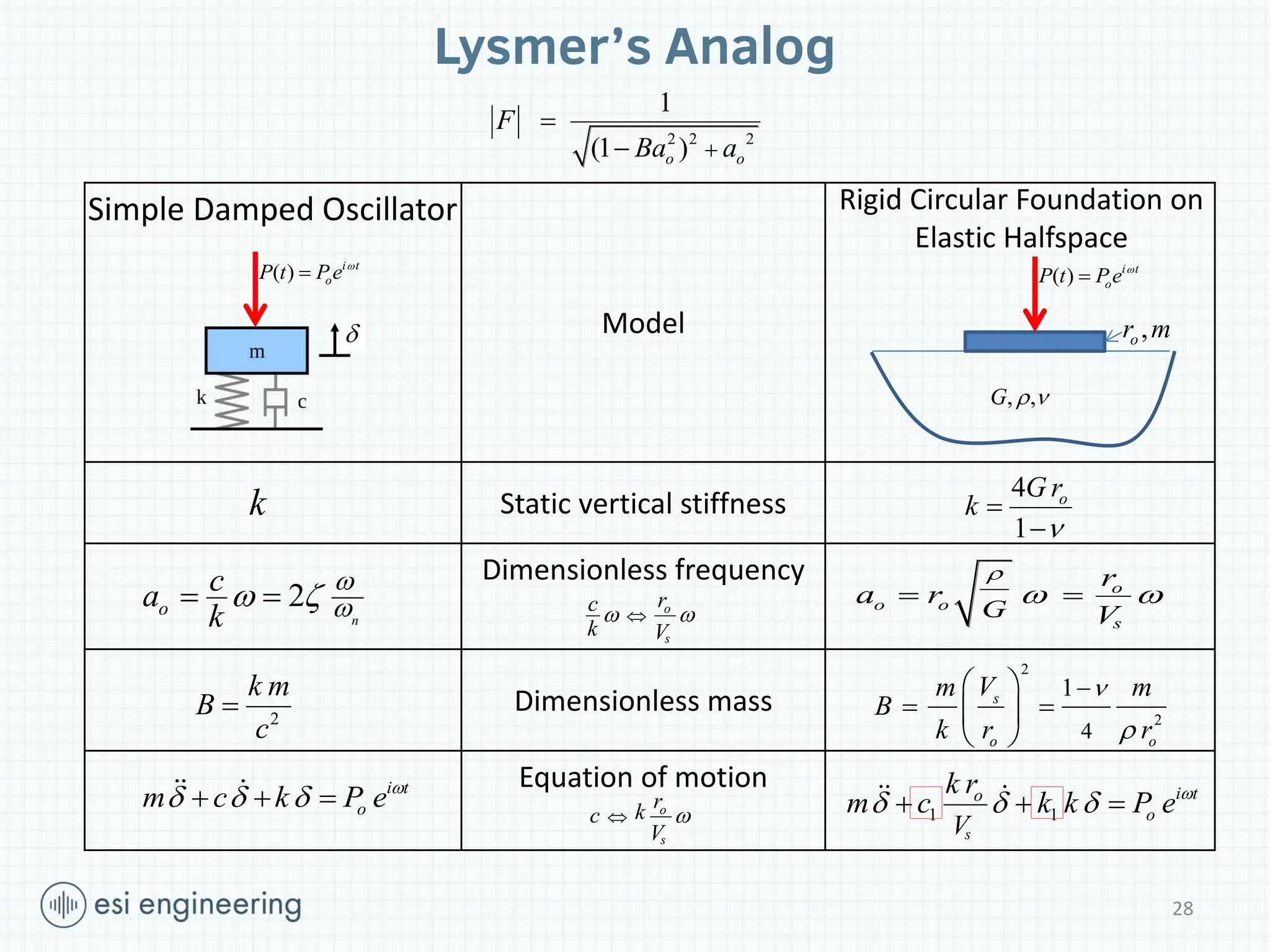
28.
Model
Static vertical stiffness
Dimensionlessfrequency
Dimensionless mass
Equation of motion
Lysmer’s Analog
Simple Damped Oscillator
2
n
o
c
a
k
2 2 2
1
(1 )
o o
F
Ba a
2
k m
B
c
4
1
o
G r
k
, ,
G
,
o
r m
Rigid Circular Foundation on
Elastic Halfspace
o
o o
s
G
r
a r
V
2
2
4
1
s
o o
V
m m
B
k r r
k
( ) i t
o
P t Pe
( ) i t
o
P t Pe
1 1
s
i t
o
o
V
k r
m c k k P e
i t
o
m c k P e
o
s
r
c
k V
o
s
r
k
c
V
28
29.
Lysmer’s Analog
, ,
G
,
o
r m
( ) i t
o
P t Pe
1 1
s
i t
o
o
V
k r
m c k k P e
29
30.
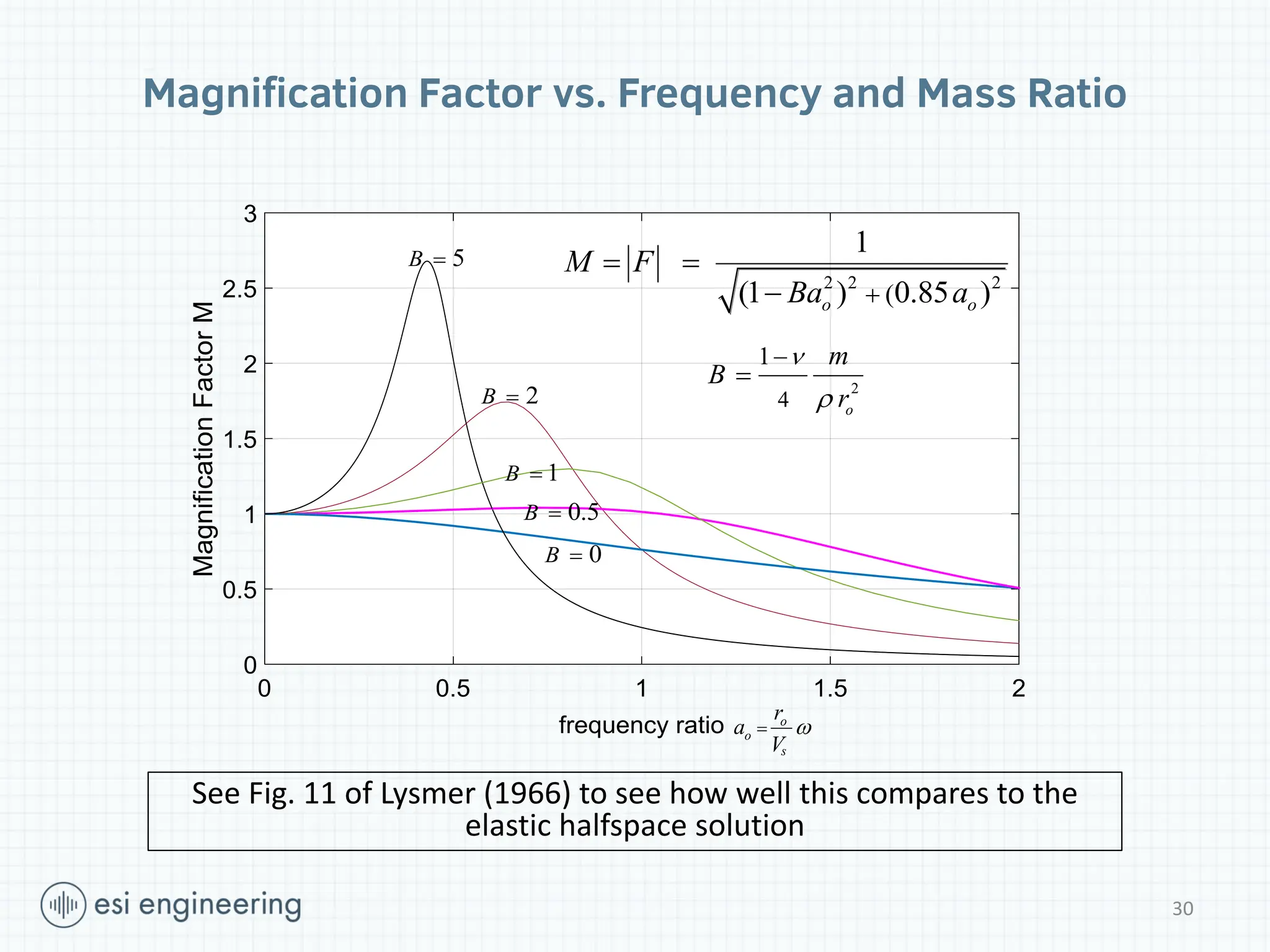
Magnification Factor vs.Frequency and Mass Ratio
2 2 2
(
1
(1 ) 0.85 )
o o
M F
Ba a
o
o
s
r
a
V
2
4
1
o
m
B
r
0.5
B
0
B
1
B
5
B
2
B
See Fig. 11 of Lysmer (1966) to see how well this compares to the
elastic halfspace solution
30
31.
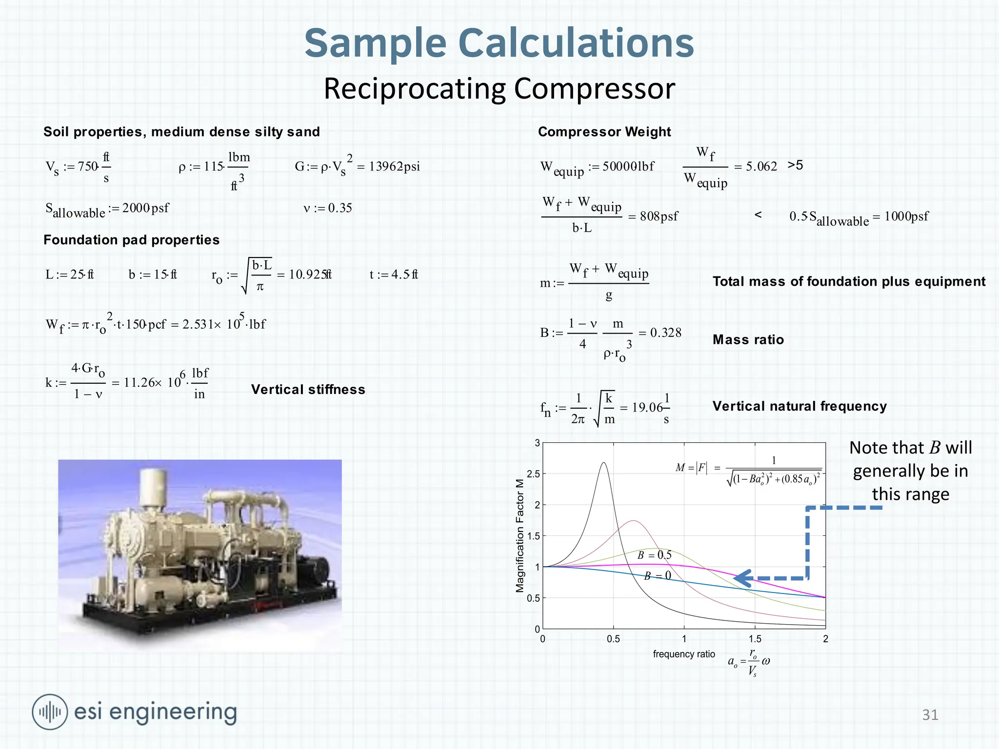
Sample Calculations
Reciprocating Compressor
o
o
s
r
a
V
22 2
(
1
(1 ) 0.85 )
o o
M F
Ba a
0.5
B
0
B
Note that B will
generally be in
this range
Soil properties, medium dense silty sand
Vs 750
ft
s
115
lbm
ft
3
G Vs
2
13962psi
Sallowable 2000psf
0.35
Foundation pad properties
L 25 ft
b 15 ft
ro
b L
10.925ft
t 4.5ft
Wf ro
2
t
150
pcf
2.531 10
5
lbf
k
4 G
ro
1
11.26 10
6
lbf
in
Vertical stiffness
Compressor Weight
Wequip 50000lbf
Wf
Wequip
5.062
>5
Wf Wequip
b L
808psf
< 0.5Sallowable
1000psf
m
Wf Wequip
g
Total mass of foundation plus equipment
B
1
4
m
ro
3
0.328
Mass ratio
fn
1
2
k
m
19.06
1
s
Vertical natural frequency
31
32.
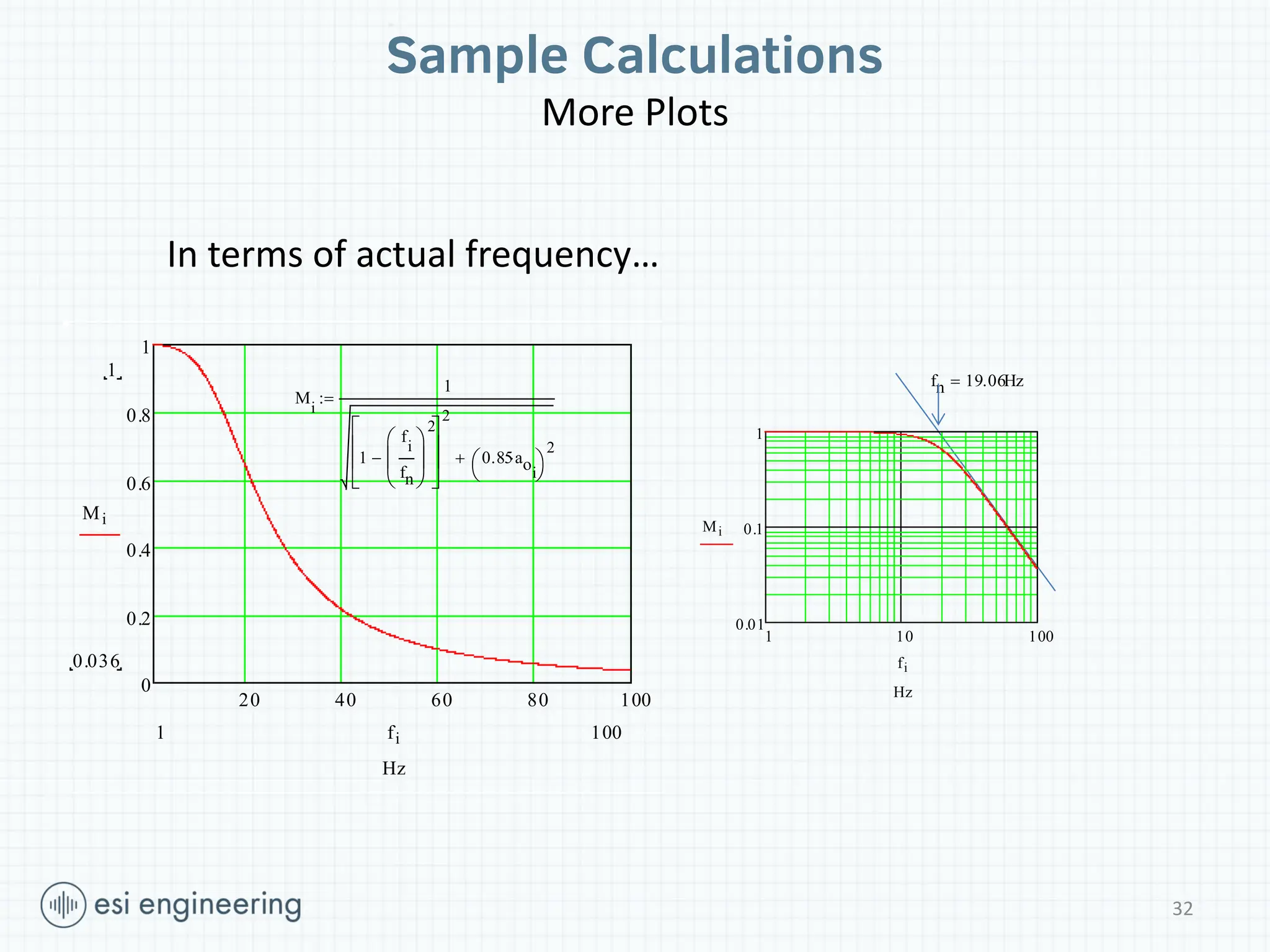
Sample Calculations
More Plots
2040 60 80 100
0
0.2
0.4
0.6
0.8
1
1
0.036
Mi
100
1 fi
Hz
1 10 100
0.01
0.1
1
Mi
fi
Hz
M
i
1
1
f
i
fn
2
2
0.85aoi
2
fn 19.06Hz
In terms of actual frequency…
32
33.
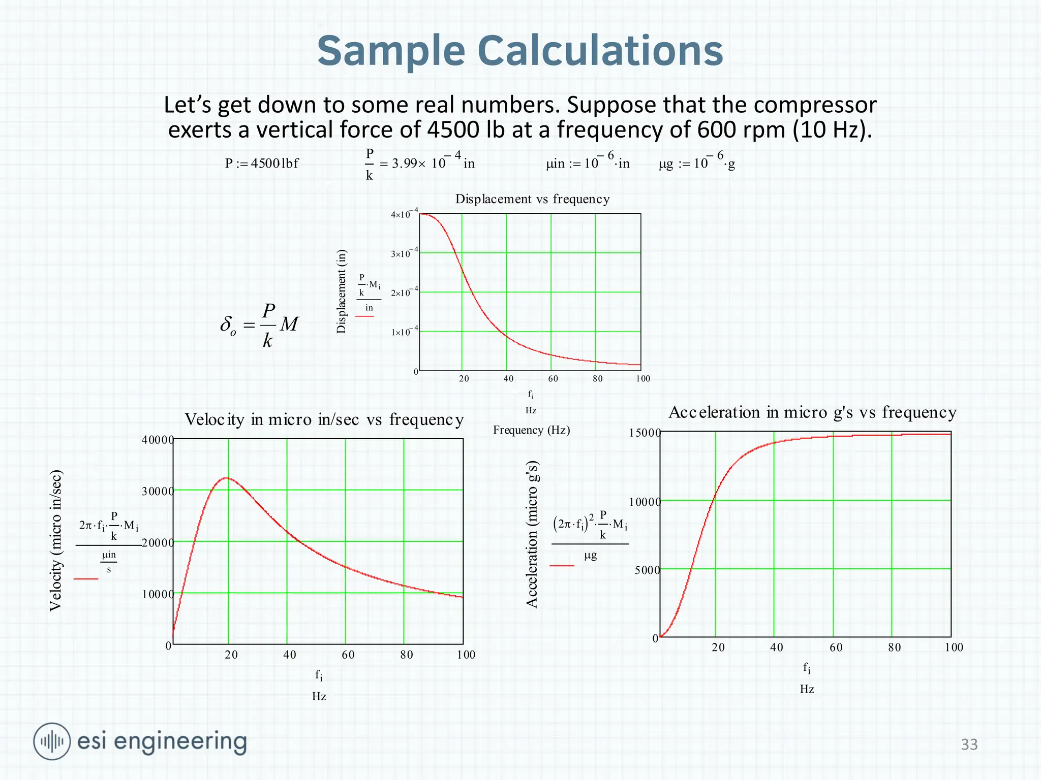
Sample Calculations
o
P
M
k
Let’sget down to some real numbers. Suppose that the compressor
exerts a vertical force of 4500 lb at a frequency of 600 rpm (10 Hz).
P 4500lbf
P
k
3.99 10
4
in
in 10
6
in
g 10
6
g
20 40 60 80 100
0
1 10
4
2 10
4
3 10
4
4 10
4
Displacement vs frequency
Frequency (Hz)
Displacement
(in)
P
k
Mi
in
fi
Hz
20 40 60 80 100
0
10000
20000
30000
40000
Velocity in micro in/sec vs frequency
Velocity
(micro
in/sec)
2 fi
P
k
Mi
in
s
fi
Hz
20 40 60 80 100
0
5000
10000
15000
Acceleration in micro g's vs frequency
Acceleration
(micro
g's)
2 fi
2 P
k
Mi
g
fi
Hz
33
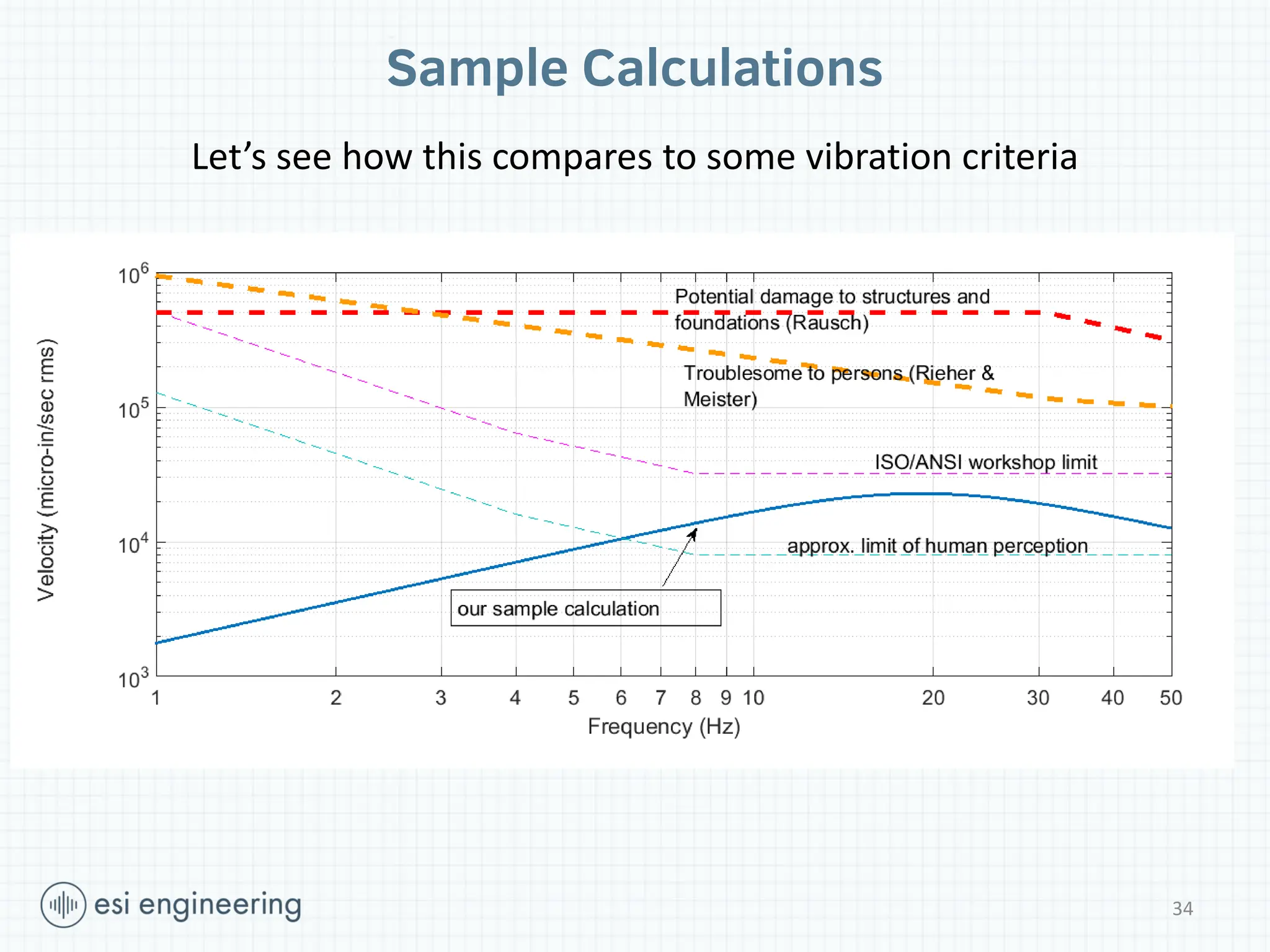
Sample Calculations
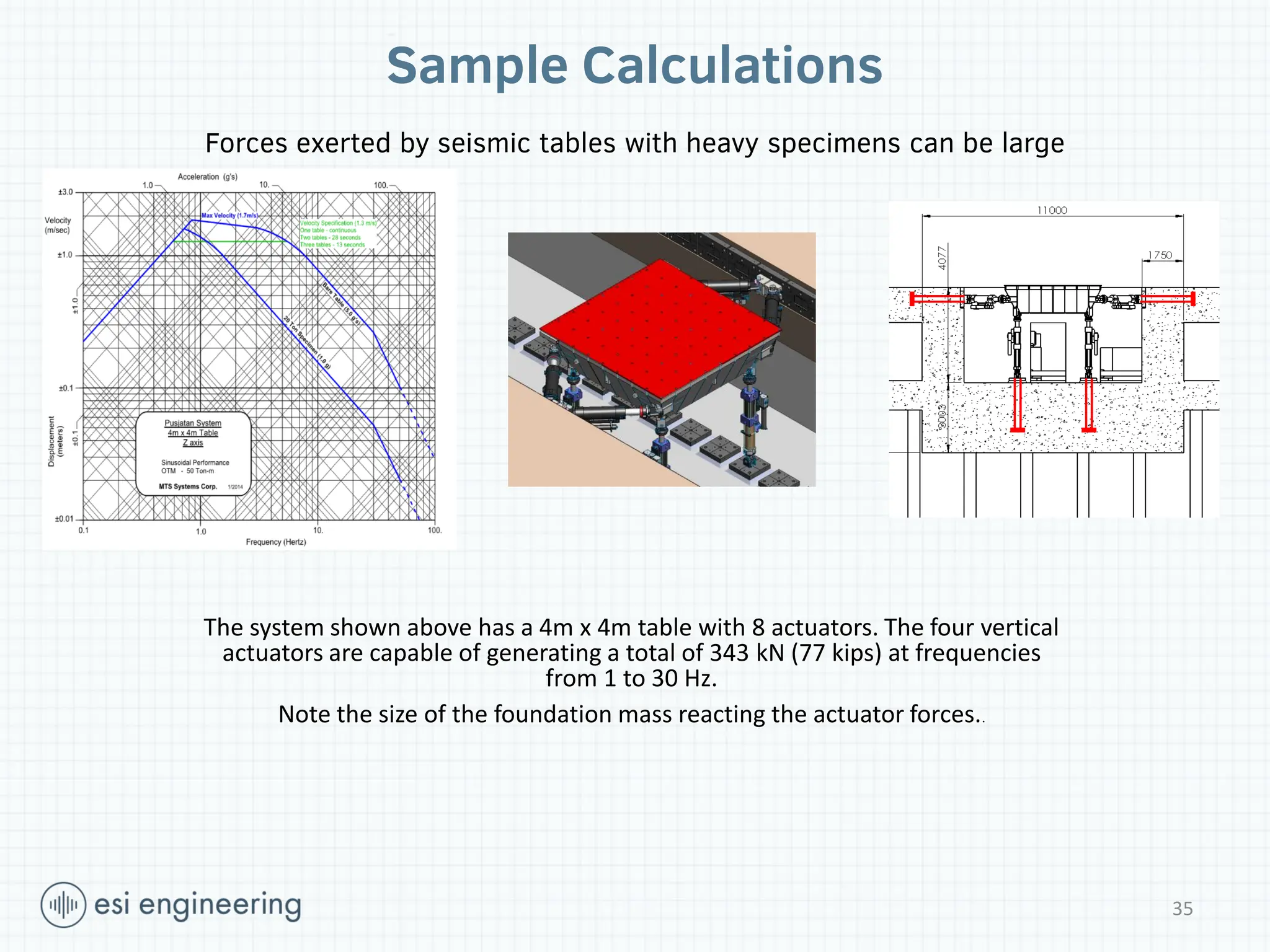
Forces exertedby seismic tables with heavy specimens can be large
The system shown above has a 4m x 4m table with 8 actuators. The four vertical
actuators are capable of generating a total of 343 kN (77 kips) at frequencies
from 1 to 30 Hz.
Note the size of the foundation mass reacting the actuator forces..
35
36.
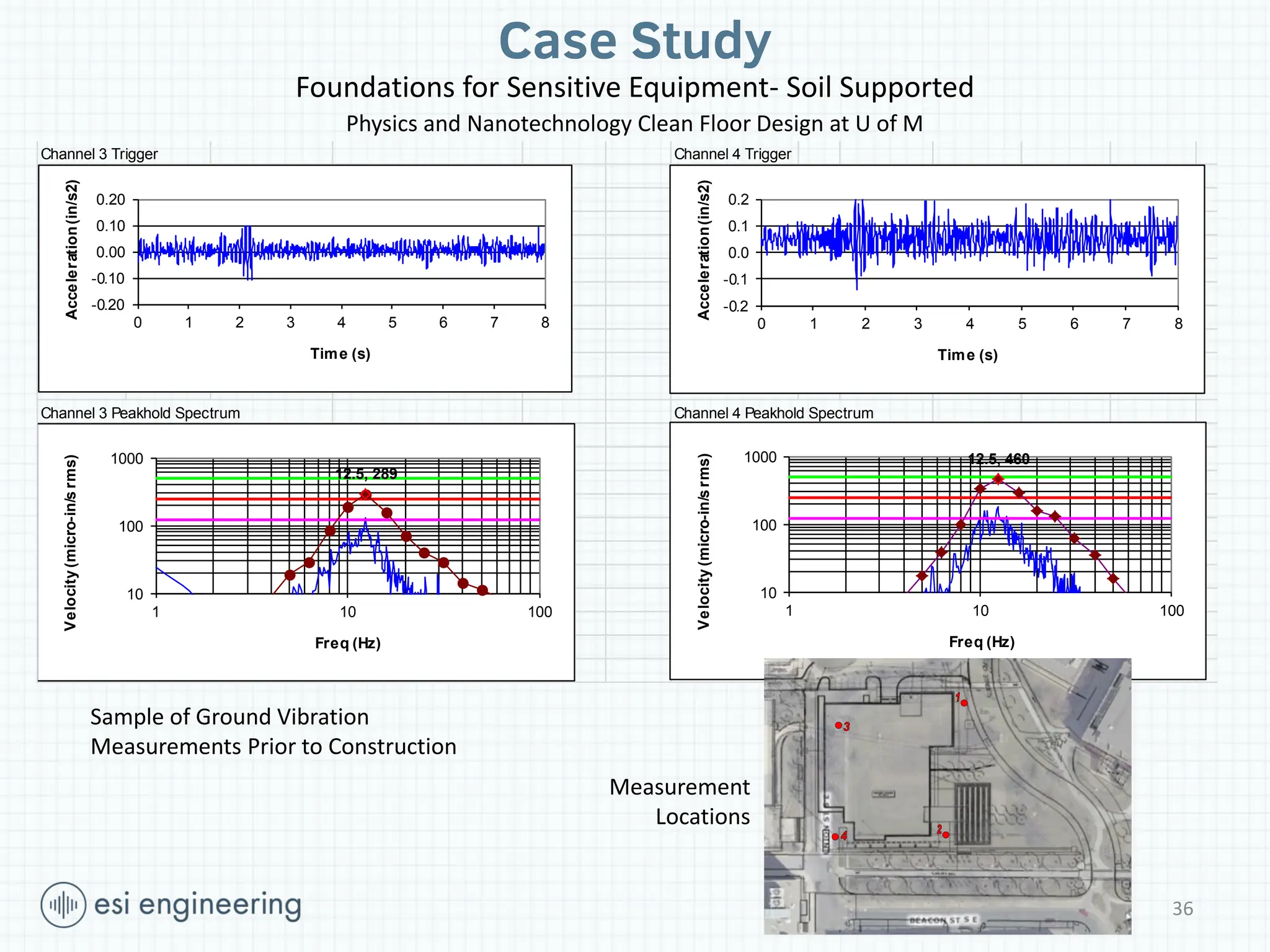
Case Study
Foundations forSensitive Equipment- Soil Supported
Physics and Nanotechnology Clean Floor Design at U of M
Project / Location: P1721- U of M Physics & Nanotech Building Measurement ID: File: TEST004.AE2 Record Date and Time :12/20/2010 1:35:53 PM
Date: 20-Dec-10 Channel 3: Sidewalk NW corner
Conditions: Delivery truck leaving by CH 4 Channel 4: Asphalt SW corner
Setup: 90%overlap, hanning window, delta f = 0.125 Hz Vibration Criteria VC-C (green), VC-D, VC-E
Channel 3 Trigger Channel 4 Trigger
Channel 3 Peakhold Spectrum Channel 4 Peakhold Spectrum
-0.20
-0.10
0.00
0.10
0.20
0 1 2 3 4 5 6 7 8
Acceleration
(in/s2)
Time (s)
-0.2
-0.1
0.0
0.1
0.2
0 1 2 3 4 5 6 7 8
Acceleration
(in/s2)
Time (s)
12.5, 289
10
100
1000
1 10 100
Velocity
(micro-in/s
rms)
Freq (Hz)
12.5, 460
10
100
1000
1 10 100
Velocity
(micro-in/s
rms)
Freq (Hz)
36
Measurement
Locations
Sample of Ground Vibration
Measurements Prior to Construction
37.
N
37
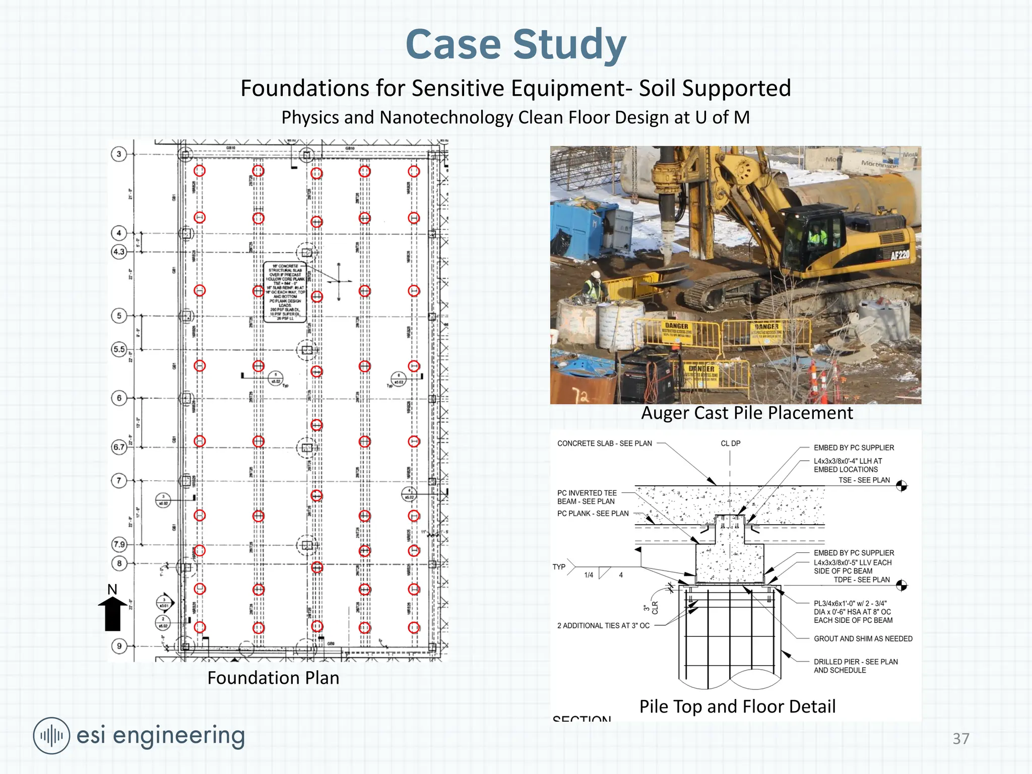
Case Study
Foundations forSensitive Equipment- Soil Supported
Physics and Nanotechnology Clean Floor Design at U of M
Auger Cast Pile Placement
Pile Top and Floor Detail
Foundation Plan
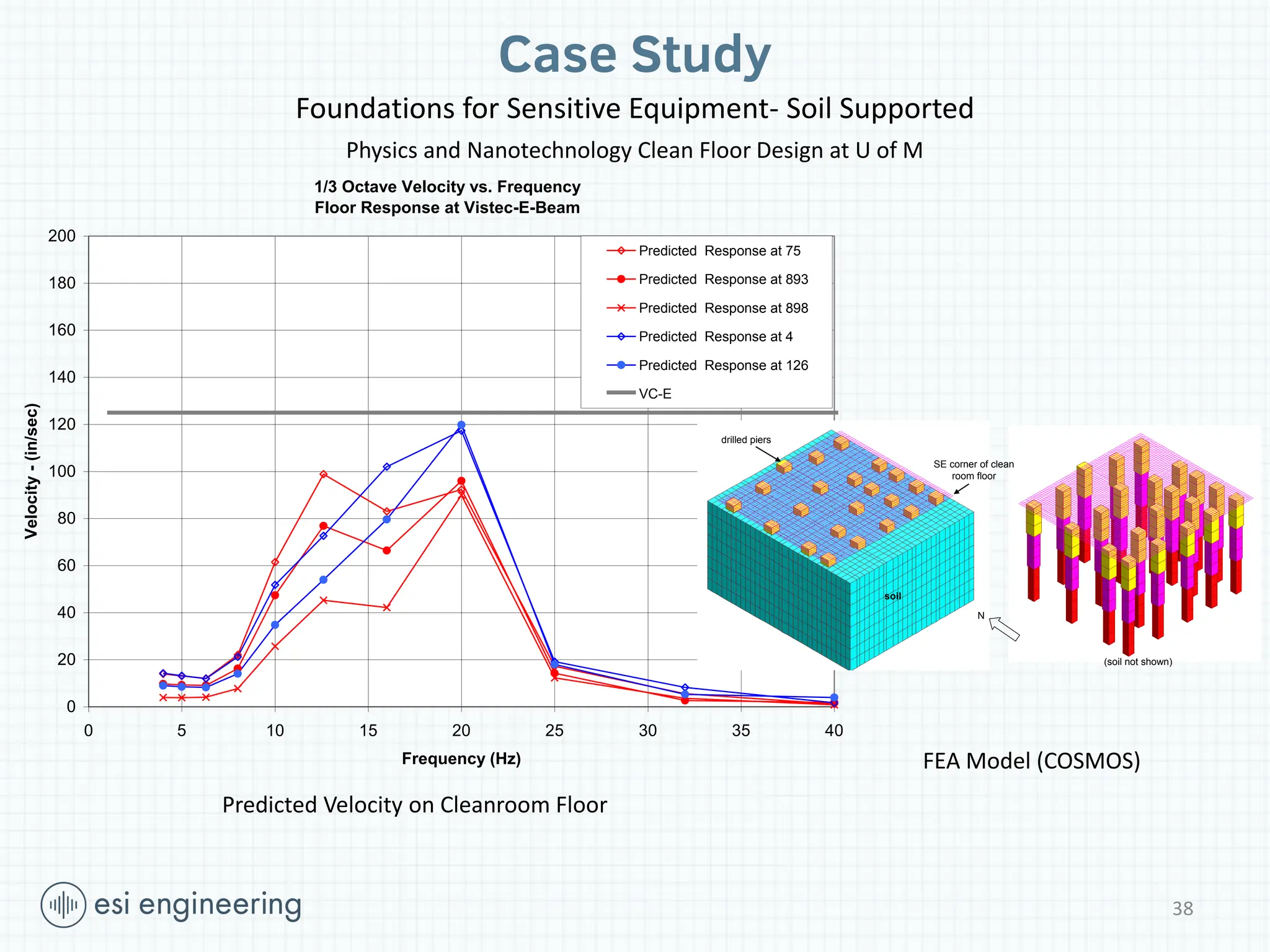
38.
1/3 Octave Velocityvs. Frequency
Floor Response at Vistec-E-Beam
0
20
40
60
80
100
120
140
160
180
200
0 5 10 15 20 25 30 35 40
Frequency (Hz)
Velocity
-
(in/sec)
Predicted Response at 75
Predicted Response at 893
Predicted Response at 898
Predicted Response at 4
Predicted Response at 126
VC-E
38
SE corner of clean
room floor
soil
drilled piers
(soil not shown)
N
Case Study
Foundations for Sensitive Equipment- Soil Supported
Physics and Nanotechnology Clean Floor Design at U of M
Predicted Velocity on Cleanroom Floor
FEA Model (COSMOS)
39.
ACI Committee 351–
Foundations for Equipment and Machinery
Active Committee Documents:
• 351.1R-12: Report on Grouting between Foundations and Bases for Support of Equipment and
Machinery
• 351.2R-10: Report on Foundations for Static Equipment
• 351.3R-04: Foundations for Dynamic Equipment
• 351.4-14: Specification for Installation of Cementitious Grouting between Foundations and
Equipment Bases
• 351.5-15 Specification for Installation of Epoxy Grout between Foundations and Equipment Bases
Documents Under Development:
• 351.3R: Foundations for Dynamic Equipment
• 351.4M-14: Specification for Installation of Cementitious Grouting between Foundations and
Equipment Bases
• 351.5M-15: Specification for Installation of Epoxy Grouting between Foundations and Equipment
Bases
39
40.
Wrap Up
Important TopicsWe Have Not Talked About Today
Rotational and Horizontal Modes
Embedment Effects
Strength Requirements
Anchorage
Numerical Methods/Software
Questions?
Thank you for inviting us!
40


![mechanical_vibration,_unit_2_ppt,_krishna_R [1].pptx](https://cdn.slidesharecdn.com/ss_thumbnails/mechanicalvibrationunit2pptkrishnar1-241012094100-79ebc2a2-thumbnail.jpg?width=640&height=640&fit=bounds)


