Download to read offline
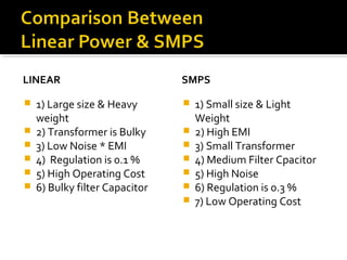
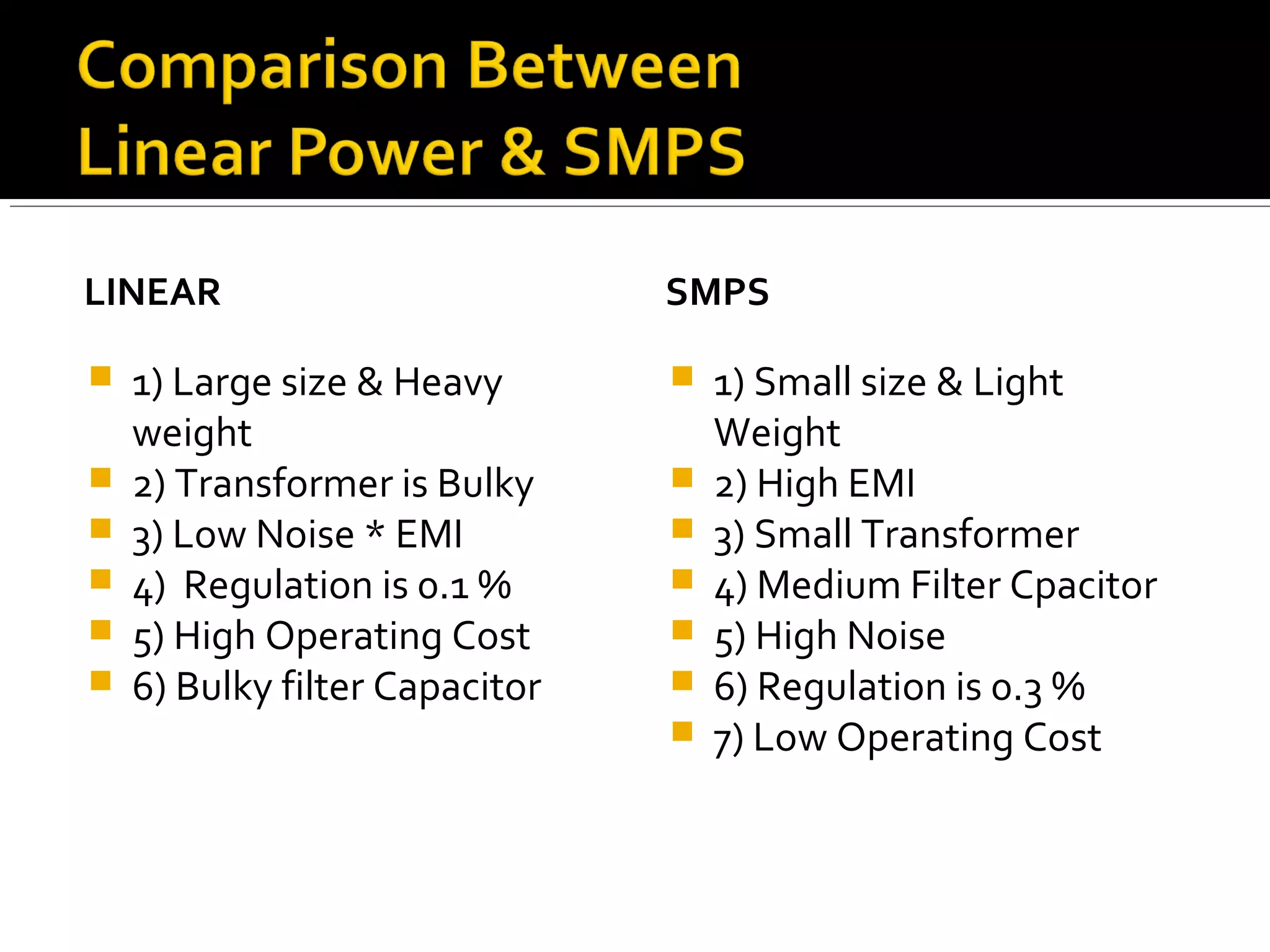
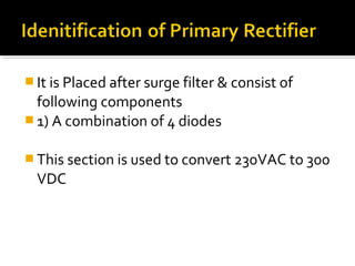
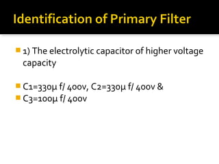
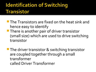
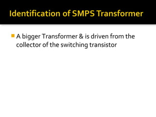


The document compares the properties of linear and SMPS power supplies. Linear power supplies are large, heavy, and have low operating costs but produce low noise. SMPS power supplies are smaller, lighter, and have higher operating costs but produce more noise. The document then describes the components and operation of a typical SMPS circuit, including the rectifier, filter capacitors, switching transistor, driver circuitry, transformers, rectifier diodes, and output filter components. It notes that a driver circuit is needed between the PWM IC and switching transistor due to the low output of the PWM IC.