Download to read offline

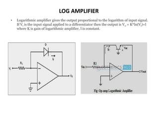
![• ID = IS.[eq(Vbe)/kT – 1]
Where,
– IS = the saturation current,
– k = Boltzmann’s constant
– T = absolute temperature (in K)
• Since IE = IC for grounded base transistor,
ID = IS. [eq(Vbe)/kT – 1]
(ID/IS) = [eq(Vbe)/kT – 1]
(ID/IS) + 1 = [eq(Vbe)/kT]
(ID+IS)/IS = eq(Vbe)/kT
eq(Vbe)/kT = (ID/IS) since ID >> IS
• Taking natural log on both sides of the above equation, we get
Vbe = (kT/q) ln[ID/IS]
• The collector current ID = Vin/R1 and Vout = -Vbe
• and ID =IF
Vout = -(kT/q) ln[Vin/R1.IS]](https://image.slidesharecdn.com/voltagesources-200621130311/85/Voltage-sources-11-320.jpg)

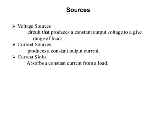
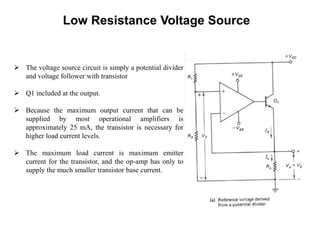
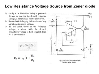
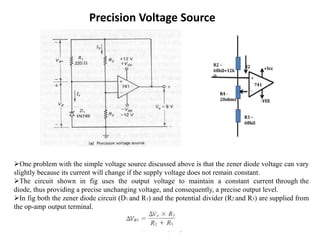
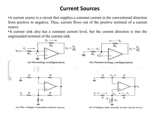
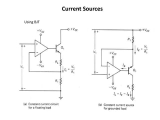
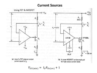
This document discusses various op-amp applications including voltage sources, current sources, and current sinks. It then describes implementations of low resistance voltage sources using a transistor, and using a zener diode. A precision voltage source is also described that uses feedback to maintain a constant current through the zener diode. Current sources using BJTs, FETs, and MOSFETs are briefly mentioned. The document concludes by discussing op-amp circuits that use diodes, including log amplifiers, antilog amplifiers, and various rectifier circuits.


