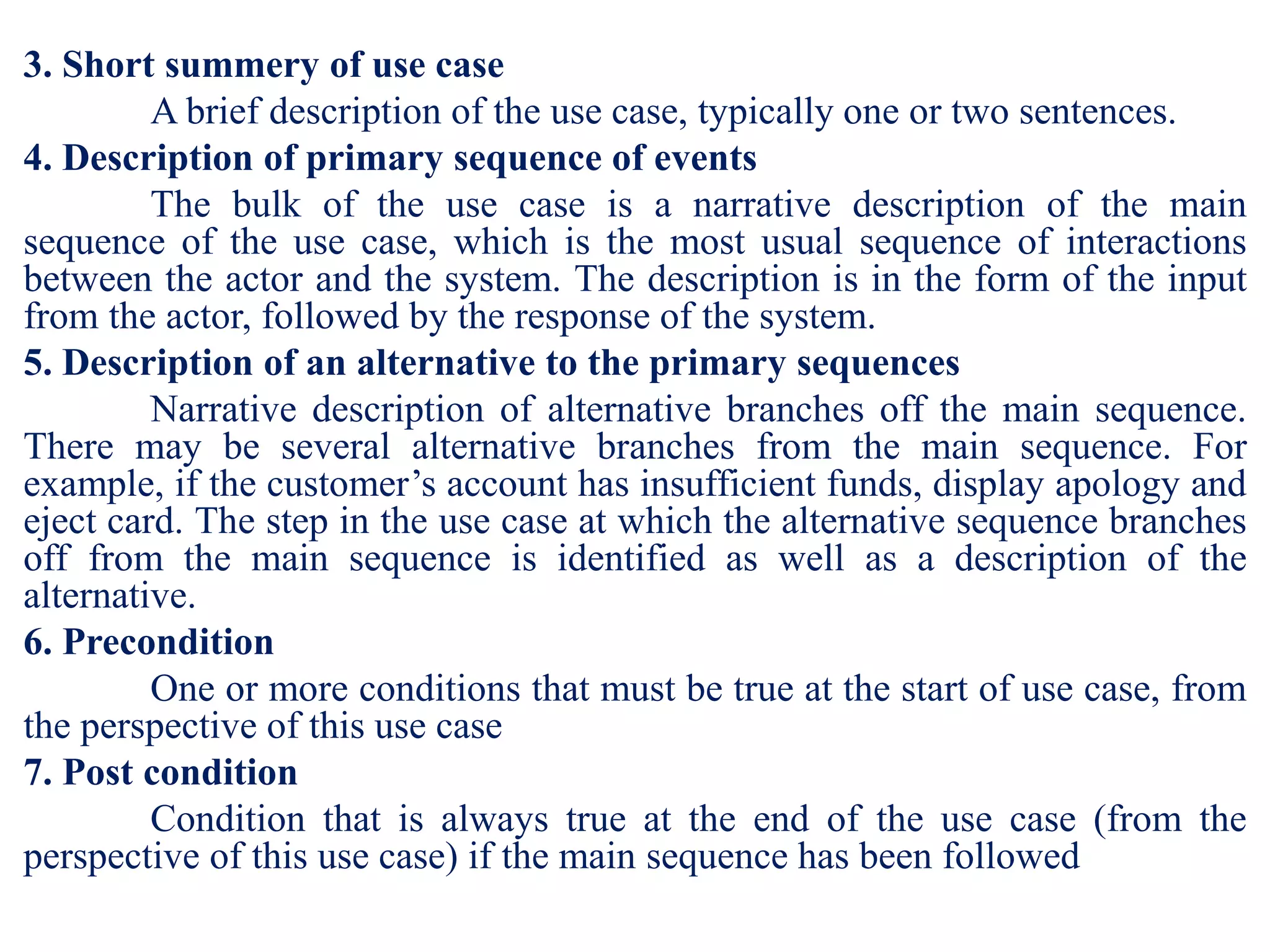
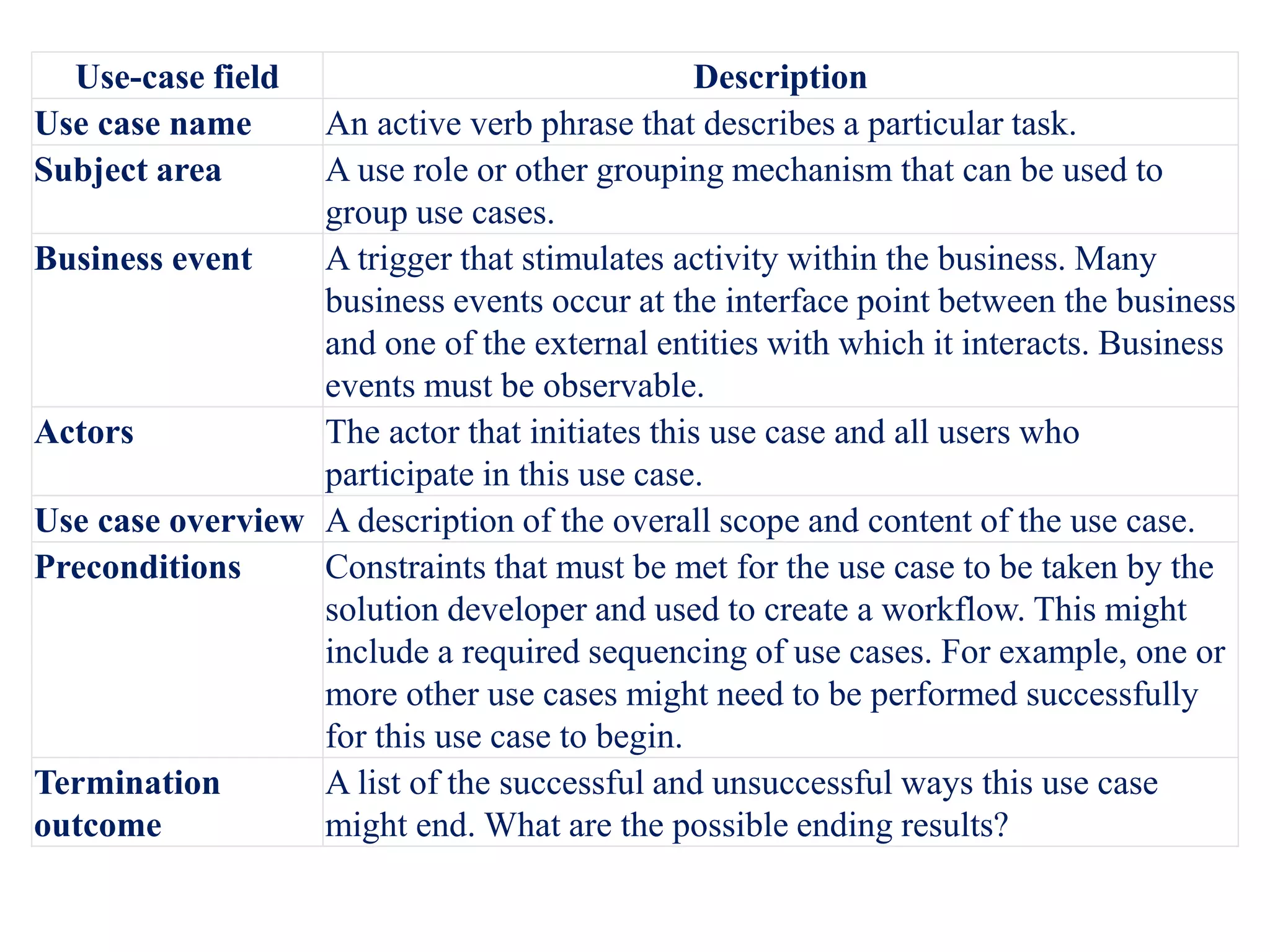
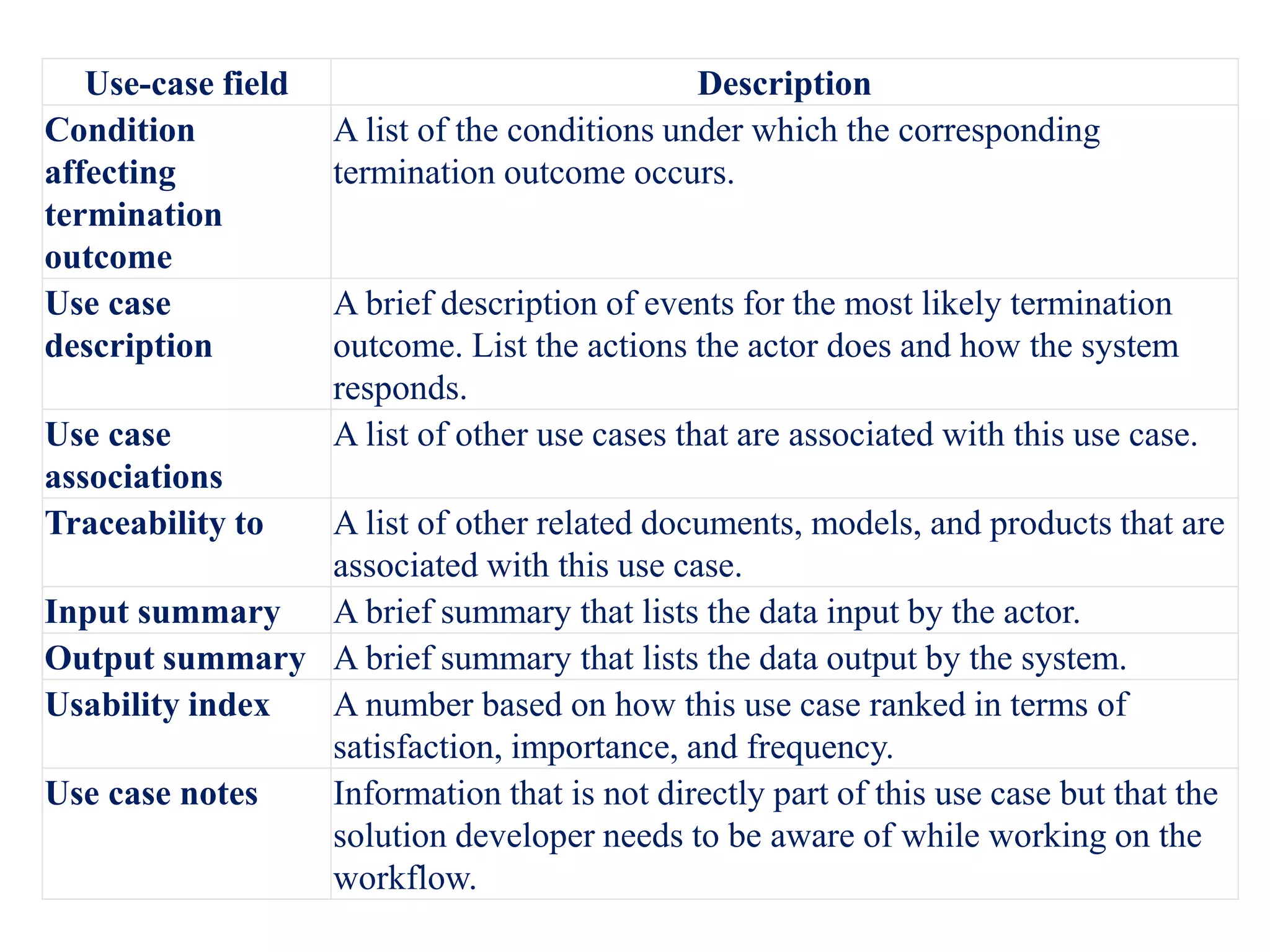
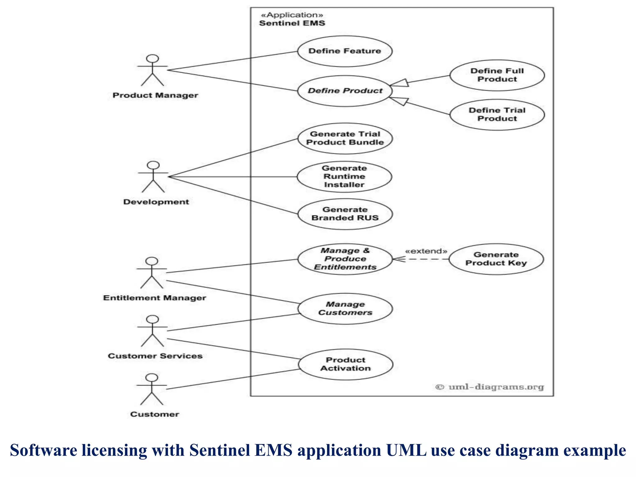
SlideShare a Scribd company logo
1 of 61
Design methods-Procedural,
structural and object oriented
• Procedural design method: Design decisions are made even when
the system functionality is not understood properly or even when all
information is not available. These languages programs in such a
way that the program executes statement by statement, reading
and modifying a shared memory. The program communicate with
the OS are through a set of procedure, or function, which in turn is
a group of specific instructions executed one after the other.
• The challenge was to keep track of the order in which the functions
are called and what data was changed.
• Structural Design method: This design method organize the
entire system in well defined modules. It is based on Top down
methodology in which the system is further divided into subsystem
typically called as functions.
• Structured programming is not only limited to the top down
approach. It employs methods using:-
1. Top down analysis for problem solving: It focuses on dividing the
problem into sub parts and hence simplifies the problem solving.
2. Modularization for program structure and organization: It organizes
large instructions by breaking them into separate and smaller section
of modules, sub routines and subprograms. Codes is became Easy and
Readability of Code also Increased.
• Object oriented design method: In this method we take a slightly
different view of systems development from what we have
examined before. the object-oriented approach combines data and
processes (called methods) into single entities called objects.
Objects usually correspond to the real things a system deals with,
such as customers, suppliers etc. Objects are central concept in
object orientation. The concepts that mostly address in object
oriented design method is classes, objects, inheritance,
polymorphism etc.
Procedural Structural Object Oriented
1.Simple, easy
implementation of
compilers and
interpreters
2. The ability to re-use
the same code at
different places in the
program without
copying it.
3. An easier way to keep
track of program flow.
4. The ability to be
strongly modular or
structured.
5. Needs only less
memory.
1. Programs are more
easily and more quickly
written
2. Programs are reliable
as fewer organizational
and logical errors occur
during the initial stages
of program
development.
1. Improved software
development
productivity due to
modularity, extensibility
and reusability.
2. Software
Maintenance is
improved
3. Reusability helps in
faster development of
programs, as the
language comes worth
rich library of objects
4. Lower cost of
Development
5. Higher quality of
software can be ensured
Requirement Vs Analysis Vs
Architecture Vs Design Vs
Development 4+1 Architecture
• In November 1995, while working as Lead software architect at
Hughes Aircraft Of Canada Philippe Kruchten published a paper
entitled: "Architectural Blueprints—The “4+1” View Model of
Software Architecture". The intent was to come up with a
mechanism to separate the different aspects of a software system
into different views of the system. Why? Because different
stakeholders always have different interest in a software system.
Some aspects of a system are relevant to the Developers; others are
relevant to System administrators. The Developers want to know
about things like classes; System administrators want to know
about deployment, hardware and network configurations and don't
care about classes. Similar points can be made for Testers, Project
Managers and Customers. Kruchten thought it made sense to
decompose architecture into distinct views so stakeholders could
get what they wanted. In total there were 5 views in his approach
but he decided to call it 4 + 1.
1. The logical view
Also called as static modelling view. This contains information about
the various parts of the system (provides functionalities offered to end
users.). In UML the logical view is modelled using Class, Object,
State machine and Interaction diagrams (e.g Sequence diagrams). It's
relevance is really to developers.
2. The process view
Also called as task view, concerned with dynamic or run time aspect.
This describes the concurrent processes within the system. It
encompasses some non-functional requirements such as performance
and availability. In UML, Activity diagrams - which can be used to
model concurrent behavior - are used to model the process view.
3. The development view
The development view focusses on software modules and subsystems.
Also called as subsystem view. This is the developer’s view. In UML,
Package and Component diagrams are used to model the development
view.
4. The physical view
The physical view describes the physical deployment of the
system. For example, how many nodes are used and what is
deployed on what node. Thus, the physical view concerns some
non-functional requirements such as scalability and availability.
In UML, Deployment diagrams are used to model the physical
view.
5. The use case view (Scenarios)
This view describes the functionality of the system from the
perspective from outside world. It contains diagrams describing
what the system is supposed to do from a black box perspective.
This view typically contains Use Case diagrams. All other views
use this view to guide them.
• Scenarios
In 4+1 view model we have scenario at center represented in the
form of small set of use cases.
Another popular view model is proposed by Hofmeister which is for
industrial perspective. It has four views as shown below
1. Conceptual view: The primary design elements are described in
this view. The relationship of design elements also described.
2. Code view: It is the developers view, describe the structure of
source code and their classification into objects. It also describe code
grouping into libraries and packages.
3. Module view: It describes modules and sub modules and their
interactions.
4. Execution view: It is used for concurrent and descriptive
perspective. It deals with run time.
• In 4+1 view model we have scenario at center represented in the
form of small set of use cases. the different modeling views of the
software architecture in UML. The views are as follows:
1. Use case view: This view is a functional requirements view, which
is an input to develop the software architecture. Each use case
describes the sequence of interactions between one or more actors
(external users) and the system.
2. Static view: The architecture is depicted in terms of classes and
relationships, which can be associations, whole/part relationships
(compositions or aggregations), or generalization/specialization
relationships. Depicted on UML class diagrams.
3. Dynamic interaction view: This view describes the architecture in
terms of objects as well as the message communication between them.
This view can also be used to depict the execution sequence of
specific scenarios. Depicted on UML communication diagrams.
4. Dynamic state machine view: The internal control and sequencing
of a control component can be depicted using a state machine.
Depicted on UML state chart diagrams.
5. Structural component view: The software architecture is depicted
in terms of components, which are interconnected through their ports,
which in turn support provided and required interfaces. Depicted on
UML structured class diagrams.
6. Dynamic concurrent view: The software architecture is viewed as
concurrent components, executing on distributed nodes, and
communicating by messages. Depicted on UML concurrent
communication diagrams.
7. Deployment view: This depicts a specific configuration of the
distributed architecture with components assigned to hardware nodes.
Depicted on UML deployment diagrams.
UP-Unified Process
• Software industry uses some well defined process model for
developing software. This model is called as Software Engineering
Process (SEP) or Software Development Process (SDP)
• The Unified Software Development Process (USDP) is a popular,
widely used industry standard of SDP. In short it is also called as
Unified Process (UP).
• The USDP consists of five core workflows and four phases and is
iterative, as shown in Figure. An artifact is defined as a piece of
information that is produced, modified, or used by a process. A
workflow is defined as a sequence of activities that produces a
result of observable value. A phase is defined as the time between
two major milestones during which a well-defined set of objectives
is met, artifacts are completed, and decisions about whether to
move on to the next phase are made.
• There is usually more than one iteration in a phase; thus, a phase
iteration in USDP corresponds to a cycle in the spiral model.
• Each cycle goes through all four phases and addresses the
development of a core workflow. The workflows and products of
each workflow are as follows:
1. Requirements. The product of the requirements workflow is the
use case model.
2. Analysis. The product of the analysis workflow is the analysis
model.
3. Design. The products of the design workflow are the design model
and the deployment model.
4. Implementation. The product of the implementation workflow is
the implementation model.
5. Test. The product of the test workflow is the test model.
• Phases of UP:
1. Inception : The primary focus of inception phase is gathering and
analyzing the requirements. Business workflow is understood clearly, risk is
analyzed in this phase. Outputs of inception phase are project plan, business
case, prototypes, vision document, SRS etc.
2. Elaboration: The deliverables of inception phase are elaborated in the
elaboration phase. Risk is refined and detailed system construction plan is
created. The focus in this phase is on executable architecture for system
construction. The deliverables of this phase are static and dynamic UML
model.
3. Construction: The architectural baseline of previous phase is converted
into final system in construction phase. This phase is strictly follows the
architectural baseline and maintain its integrity. Requirements, analysis,
design are finalized in this phase and code become started to built initial
capability if proposed system
4. Transition: This phase starts when system is finally deployed and tests are
finished. All bugs, errors, defects are analyzed and fixed in this phase.
Release of software to users is prepared. The final software is ready.
Introduction to UML
• The Unified Modeling Language (UML) is a general purpose visual
modeling language for systems. UML was designed to incorporate
current best practice in modeling techniques and software
engineering. As such, it is explicitly designed to be implemented by
computer-assisted software engineering (CASE) tools. This is in
recognition of the fact that large, modern software systems
generally require CASE support. UML diagrams are human-
readable.
Basic Building Blocks
• UML is composed of just three building blocks:
1. things – these are the modeling elements themselves
2. relationships – these tie things together – relationships specify how
two or more things are semantically related
3. diagrams – these are views into UML models – they show
collections of things that “tell a story” about the software system and
are our way of visualizing what the system will do (analysis-level
diagrams) or how it will do it (design-level diagrams).
1. Things: UML things may be partitioned into:
a) Structural things – the nouns (static components) of a UML model
such as class, interface, collaboration, use case, active class,
component, node;
b) Behavioral things – the verbs (activities between structural things)
of a UML model such as interactions, state machines;
c) Grouping things – the package, which is used to group
semantically related modeling elements into cohesive units;
d) Annotation things – the note (extra information attached to
elements), which may be appended to the model to capture ad hoc
information, very much like a yellow sticky note.
2. Relationships : Relationships allow you to show on a model how
two or more things relate to each other. Relationships apply to the
structural and grouping things in a model and are depicted in Figure
1. Association: The description of a set of links between objects
2. Dependency: A change to a thing affects the semantics of a
dependent thing
3. Generalization: One element is a specialization of another and
may be substituted for the more general element
4. Realization A relationship between classifiers where one
classifier specifies a contract that the other classifier guarantees to
carry out
2. Diagrams: The views of UML is called as diagram. There are a
total of nine different types of UML diagram and these are listed in
Figure
• We can usefully divide this set of diagrams into those that model
the static structure of the system (the so-called static model) and
those that model the dynamic structure of the system (the dynamic
model). The static model captures the things and the structural
relationships between things; the dynamic model captures how
things interact to generate the required behavior of the software
system.
• There is no specific order in which UML diagrams are created,
although you typically start with a use case diagram to define the
system scope. In fact, you often work on several diagrams in
parallel, refining each one as you uncover more and more
information and detail about the software system you are designing.
Thus, the diagrams are both a view of the model and the primary
mechanism for entering information into the model.
COMET Based Software Lifecycle
• UML based software modeling and architecture design method is
often called as COMET (Concurrent/Collaborative Object
Modeling and Architecture Design Method). This is a specification
of entire system and covers the entire project development life
cycle.
• The COMET method ties in the three phases of requirements,
analysis, and design modeling by means of a use case–based
approach
1. Requirement modeling phase
During the requirements modeling phase, a requirements
model is developed in which the functional requirements of the system
are described in terms of actors and use cases. A narrative description
of each use case is developed. User inputs and active participation are
essential to this effort.
2. Analysis modeling phase
In the analysis modeling phase, static and dynamic models of
the system are developed. The static model defines the structural
relationships among problem domain classes. The classes and their
relationships are depicted on class diagrams. Object structuring criteria
are used to determine the objects. A dynamic model is then developed
in which the use cases from the requirements model are realized to
show the objects that participate in each use case and how they interact
with each other. Objects and their interactions are depicted on either
communication diagrams or sequence diagrams.
3. Design modeling phase
In the design modeling phase, the software architecture of the
system is designed, in which the analysis model is mapped to an
operational environment. The analysis model, with its emphasis on the
problem domain, is mapped to the design model, with its emphasis on
the solution domain. Subsystem structuring criteria are provided to
structure the system into subsystems.
Reusability
• Software reusability is the extent to which software is
capable of being reused. In traditional software reuse, a library
of reusable code components is developed – for example, a
statistical subroutine library.
• Instead of reusing an individual component, it is much more
advantageous to reuse a whole design or subsystem that
consists of the components and their interconnections. This
means reuse of the control structure of the application.
Architecture reuse has much greater potential than component
reuse because it is large grained reuse, which focuses on reuse
of requirements and design.
Use case modelling
• Use cases
UML supports both the aspects of modeling: static and
dynamic. Static modeling captures static information of the system at
the beginning. Dynamic modelling captures runtime behavior of the
system. In the use case modeling approach, functional requirements
are described in terms of actors, which are users of the system, and use
cases. A use cases capture the functionality of the system from user’s
perspective. A use case defines a sequence of interactions between one
or more actors and the system. In the requirements phase, the use case
model considers the system as a black box and describes the
interactions between the actor(s) and the system in a narrative form
consisting of user inputs and system responses.
A use case always starts with input from an actor. A use case
typically consists of a sequence of interactions between the actor and
the system. Each interaction consists of an input from the actor
followed by a response from the system. Thus, an actor provides
inputs to the system and the system provides responses to the actor.
More complex use cases might also involve more than one
actor. Consider a simple banking example in which an automated teller
machine (ATM) allows customers to withdraw cash from their bank
accounts. There is one actor, the ATM Customer, and one use case,
Withdraw Funds, as shown in figure
The Withdraw Funds use case describes the sequence of
interactions between the customer and the system; the use case starts
when the customer inserts an ATM card into the card reader, then
responds to the system’s prompt for the PIN, and eventually receives
the cash dispensed by the ATM machine.
• A Simple Use Case
As an example of a very simple use case, consider View
Alarms from the Emergency Monitoring System. There is one actor,
the Monitoring Operator, who can request to view the status of all
alarms. The essentials of the use case description consist of the
following:
Use case name: View Alarms
Summary: The monitoring operator views outstanding alarms.
Actor: Monitoring Operator
Main sequence:
1. The monitoring operator requests to view the outstanding alarms.
2. The system displays the outstanding alarms. For each alarm, the
system displays the name of the alarm, alarm description, location of
alarm, and severity of alarm (high, medium, low).
Alternative sequences:
Step 2: Emergency situation. System displays emergency warning
message to operator.
The use case diagram shows three aspects of the system:
1. Actors: represented by arranging sticks in human shape. Used to
represent user, other system or devices that interact with particular
high level functionality.
2. Use case: Represents high level functionality of the system. Use
case is represented by ellipse inside the box (rectangle)
3. System boundary: Use cases are packed inside the box called
system boundary. Actors are outside the boundary. System boundary is
used to show the enclosure of system functionality.
Figure. Natation of use case diagram
• Use case actors:
An actor characterizes an external user (i.e., outside the
system) that interacts with the system . In the use case model, actors
are the only external entities that interact with the system. In many
information systems, humans are the only actors. In other systems,
however, there are other types of actors in addition to or in place of
human actors. Thus, it is possible for an actor to be an external system
that interfaces to the system. In some applications, an actor can also be
an external I/O device or a timer. External I/O device and timer actors
are particularly prevalent in real-time embedded systems, in which the
system interacts with the external environment through sensors and
actuators.
Primary and Secondary Actors
A primary actor initiates a use case. Thus, the use case starts
with an input from the primary actor to which the system has to
respond. Other actors, referred to as secondary actors, can participate
in the use case. A primary actor in one use case can be a secondary
actor in another use case. At least one actor must gain value from the
use case; usually, this is the primary actor. An example of primary and
secondary actors is shown in Figure
The Remote System actor initiates the Generate Monitoring
Data use case, in which the remote system sends monitoring data
that is displayed to monitoring operators. In this use case, the
Remote System is the primary actor that initiates the use case, and
the Monitoring Operator is a secondary actor who receives the
monitoring data and, hence, gains value from the use case.
• Modeling Actors
A human actor typically uses various I/O devices to
physically interact with the system. Frequently, a human actor
interacts with the system via standard I/O devices, such as a keyboard,
display, or mouse. In some cases, however, a human actor might
interact with the system via nonstandard I/O devices, such as various
sensors. In all these cases, the human is the actor and the I/O devices
are not actors. Thus, the actor is an end-user. Consider some examples
of human actors. In the Emergency Response System, an example of
an actor is the Monitoring Operator who interacts with the system via
standard I/O devices, as shown in previous example. Another example
of a human actor is an ATM customer (Figure) who interacts with the
Banking System by using several I/O devices, including a card reader,
cash dispenser, and receipt printer, in addition to a keyboard and
display.
An actor can also be an external system actor that either
initiates (as primary actor) or participates (as secondary actor) in the
use case. An example of an external system actor is the Remote
System in the Emergency Monitoring System.
In some case, an actor can be an input device actor or an
input/output device actor. This can happen when there is no human
involvement with the use case and the actor providing external input to
the system is an input device or I/O device. Typically, the input device
actor interacts with the system via a sensor. An example of an input
device actor is Monitoring Sensor, which provides sensor input to the
Generate Alarm use case shown in previous Figure. An actor can also
be a timer actor that periodically sends timer events to the system.
Periodic use cases are needed when certain information needs to be
output by the system on a regular basis. An example of a timer actor is
given in following Figure
Use case Modeling
• Essentials of use cases
1. Name of the use case
2. Names of the actor
3. Short summery of use case
4. Description of primary sequence of events
5. Description of an alternative to the primary sequences
6. Precondition
7. Post condition
1. Name of the use case
Each use case is given a name.
2. Names of the actor
This section names the actors in the use case. There is always a
primary actor that initiates the use case. In addition, there may be
secondary actors that also participate in the use case.
3. Short summery of use case
A brief description of the use case, typically one or two sentences.
4. Description of primary sequence of events
The bulk of the use case is a narrative description of the main
sequence of the use case, which is the most usual sequence of interactions
between the actor and the system. The description is in the form of the input
from the actor, followed by the response of the system.
5. Description of an alternative to the primary sequences
Narrative description of alternative branches off the main sequence.
There may be several alternative branches from the main sequence. For
example, if the customer’s account has insufficient funds, display apology and
eject card. The step in the use case at which the alternative sequence branches
off from the main sequence is identified as well as a description of the
alternative.
6. Precondition
One or more conditions that must be true at the start of use case, from
the perspective of this use case
7. Post condition
Condition that is always true at the end of the use case (from the
perspective of this use case) if the main sequence has been followed
Use case Template
• The following template is a sample from an industry standard
source and can be used to document use cases.
Table 1. Use case template
Use-case field Description
Use case name An active verb phrase that describes a particular task.
Subject area A use role or other grouping mechanism that can be used to
group use cases.
Business event A trigger that stimulates activity within the business. Many
business events occur at the interface point between the business
and one of the external entities with which it interacts. Business
events must be observable.
Actors The actor that initiates this use case and all users who
participate in this use case.
Use case overview A description of the overall scope and content of the use case.
Preconditions Constraints that must be met for the use case to be taken by the
solution developer and used to create a workflow. This might
include a required sequencing of use cases. For example, one or
more other use cases might need to be performed successfully
for this use case to begin.
Termination
outcome
A list of the successful and unsuccessful ways this use case
might end. What are the possible ending results?
Use-case field Description
Condition
affecting
termination
outcome
A list of the conditions under which the corresponding
termination outcome occurs.
Use case
description
A brief description of events for the most likely termination
outcome. List the actions the actor does and how the system
responds.
Use case
associations
A list of other use cases that are associated with this use case.
Traceability to A list of other related documents, models, and products that are
associated with this use case.
Input summary A brief summary that lists the data input by the actor.
Output summary A brief summary that lists the data output by the system.
Usability index A number based on how this use case ranked in terms of
satisfaction, importance, and frequency.
Use case notes Information that is not directly part of this use case but that the
solution developer needs to be aware of while working on the
workflow.
• Use case relationships
When use cases get too complex, dependencies between use
cases can be defined by using the include and extend relationships. The
objective is to maximize extensibility and reuse of use cases. Inclusion
use cases are determined to identify common sequences of interactions
in several use cases, which can then be extracted and reused. Another
use case relationship provided by the UML is the use case
generalization. Use case generalization is similar to the extend
relationship because it is also used for addressing variations. However,
users often find the concept of use case generalization confusing, so in
the COMET method, the concept of generalization is confined to
classes. Use case variations can be adequately handled by the extend
relationship. The dependencies and relationship of the use cases can be
described by two terms called
1. Include relationship
2. Extend relationship
1. Include relationship
After the use cases for an application are initially developed, common
sequences of interactions between the actor and the system can sometimes be
determined that span several use cases. These common sequences of
interactions reflect functionality that is common to more than one use case. A
common sequence of interactions can be extracted from several of the original
use cases and made into a new use case, which is called an inclusion use case.
When this common functionality is separated into an inclusion use
case, this use case can now be reused by other use cases. It is then possible to
define amore concise version of the old use case, with the common interaction
sequence removed. This concise version of the old use case is referred to as a
base use case (or concrete use case), which includes the inclusion use case.
An inclusion use case is executed in conjunction with a base use case,
which includes and, hence, executes the inclusion use case. In programming
terms, an inclusion use case is analogous to a library routine, and a base use
case is analogous to a program that calls the library routine. An inclusion use
case might not have a specific actor. The actor is, in fact, the actor of the base
use case that includes the inclusion use case. Because different base use cases
use the inclusion use case, it is possible for the inclusion use case to be used
by different actors.
Validate PIN Inclusion Use Case
Use case name: Validate PIN
Summary: System validates customer PIN.
Actor: ATM Customer
Precondition: ATM is idle, displaying a “Welcome” message.
Main sequence:
1. Customer inserts the ATM card into the card reader.
2. If system recognizes the card, it reads the card number.
3. System prompts customer for PIN.
4. Customer enters PIN.
5. System checks the card’s expiration date and whether the card has been reported
as lost or stolen.
6. If card is valid, system then checks whether the user-entered PIN matches the card
PIN maintained by the system.
7. If PIN numbers match, system checks what accounts are accessible with the ATM
card.
8. System displays customer accounts and prompts customer for transaction type:
withdrawal, query, or transfer.
Alternative sequences:
Step 2: If the system does not recognize the card, the system ejects the card.
Step 5: If the system determines that the card date has expired, the system
confiscates the card.
Step 5: If the system determines that the card has been reported lost or stolen, the
system confiscates the card.
Step 7: If the customer-entered PIN does not match the PIN number for this card,
the system re-prompts for the PIN.
Step 7: If the customer enters the incorrect PIN three times, the system confiscates
the card.
Steps 4–8: If the customer enters Cancel, the system cancels the transaction and
ejects the card.
Post condition: Customer PIN has been validated.
2. Extend relationship
In certain situations, a use case can get very complex, with many
alternative branches. The extend relationship is used to model alternative
paths that a use case might take. A use case can become too complex if it has
too many alternative, optional, and exceptional sequences of interactions. A
solution to this problem is to split off an alternative or optional sequence of
interactions into a separate use case. The purpose of this new use case is to
extend the old use case, if the appropriate condition holds. The use case that is
extended is referred to as the base use case, and the use case that does the
extending is referred to as the extension use case.
Under certain conditions, a base use case can be extended by a
description given in the extension use case. A base use case can be extended in
different ways, depending on which condition is true. The extend relationship
can be used as follows:
• To show a conditional part of the base use case that is executed only under
certain circumstances
• To model complex or alternative paths.
Extension points are used to specify the precise locations in the base
use case at which extensions can be added. An extension use case may extend
the base use case only at these extension points
Each extension point is given a name. The extension use case
has one insertion segment for the extension point. This segment is
inserted at the location of its extension point in the base use case. The
extend relationship can be conditional, meaning that a condition is
defined that must be true for the extension use case to be invoked. Thus,
it is possible to have more than one extension use case for the same
extension point, but with each extension use case satisfying a different
condition.
A segment defines a behavior sequence to be executed when the
extension point is reached. When an instance of the use case is executed
and reaches the extension point in the base use case, if the condition is
satisfied, then execution of the use case is transferred to the
corresponding segment in the extension use case. Execution transfers
back to the base use case after completion of the segment.
An extension point with multiple extension use cases can be
used to model several alternatives in which each extension use case
specifies a different alternative. The extension conditions are designed
such that only one condition can be true and, hence, only one extension
use case selected, for any given situation.
Checkout Customer Base Use Case
Use case name: Checkout Customer
Summary: System checks out customer.
Actor: Customer
Precondition: Checkout station is idle, displaying a “Welcome” message.
Main sequence:
1. Customer scans selected item.
2. System displays the item name, price, and cumulative total.
3. Customer repeats steps 1 and 2 for each item being purchased.
4. Customer selects payment.
5. System prompts for payment by cash, credit card, or debit card.
6. «payment»
7. System displays thank-you screen.
Pay by Cash Extension Use Case
Use case name: Pay by Cash
Summary: Customer pays by cash for items purchased.
Actor: Customer
Dependency: Extends Checkout Customer.
Precondition: Customer has scanned items but not yet paid for them.
Description of insertion segment:
1. Customer selects payment by cash.
2. System prompts customer to deposit cash in bills and/or coins.
3. Customer enters cash amount.
4. System computes change.
5. System displays total amount due, cash payment, and change.
6. System prints total amount due, cash payment, and change on receipt.
Pay by Credit Card Extension Use Case
Use case name: Pay by Credit Card
Summary: Customer pays by credit card for items purchased.
Actor: Customer
Dependency: Extends Checkout Customer.
Precondition: Customer has scanned items but not yet paid for them.
Description of insertion segment:
1. Customer selects payment by credit card.
2. System prompts customer to swipe card.
3. Customer swipes card.
4. System reads card ID and expiration date.
5. System sends transaction to authorization center containing
card ID, expiration date, and payment amount.
6. If transaction is approved, authorization center returns positive
confirmation.
7. System displays payment amount and confirmation.
8. System prints payment amount and confirmation on receipt.
• Use case Packages
For large systems, having to deal with a large number of use cases in
the use case model often gets unwieldy. A good way to handle this scale-up
issue is to introduce a use case package that groups together related use
cases. In this way, use case packages can represent high-level requirements
that address major subsets of the functionality of the system. Because
actors often initiate and participate in related use cases, use cases can also
be grouped into packages based on the major actors that use them.
Nonfunctional requirements that apply to a group of related use cases could
be assigned to the use case package that contains those use cases.
For example, in the Emergency Monitoring System, the major actors
of the system are the Remote Sensor, Monitoring Operator, and Emergency
Manager, each of whom initiates and participates in several use cases.
Figure shows an example of a use case package for the Emergency
Monitoring System – namely, the Emergency Monitoring Use Case Package,
which encompasses four use cases. The Monitoring Operator is the primary
actor of the View Alarms and View Monitoring Data use cases and a
secondary actor of the other use cases. The Remote Sensor is the primary
actor of the Generate Alarm and Generate Monitoring Data use cases.
Different examples of Use case diagrams
Let us consider the banking example again. In addition to withdrawing cash from
ATM, the ATM Customer actor is also allowed to query an account or transfer funds
between two accounts. Because these are distinct functions initiated by the customer
with different useful results, the query and transfer functions should be modeled as
separate use cases, rather than being part of the original use case. Thus, the customer
can initiate three use cases, as shown in Figure 6.7: Withdraw Funds, Query Account,
and Transfer Funds.
The main sequence of the use case describes the most common sequence of
interactions between the actor and the system. There may also be branches off the
main sequence of the use case that describe less frequent interactions between the
actor and the system. These alternative sequences are deviations from the main
sequence that are executed only under certain circumstances – for example, if the
actor makes an incorrect input to the system. Depending on the application
requirements, an alternative sequence through the use case can sometimes join up
later with the main sequence. The alternative sequences are also described in the use
case. In the Withdraw Funds use case, the main sequence is the sequence of steps for
successfully achieving a withdrawal. Alternative sequences are used to address
various error cases, such as when the customer enters the wrong PIN and must be
prompted, when an ATM card is not recognized or has been reported stolen, and so
on.
Each sequence through the use case is called a scenario. A use case usually
describes several scenarios, one main sequence and a number of alternative
sequences. Note that a scenario is a complete sequence through the use case, so a
scenario could start out executing the main sequence and then follow an alternative
branch at the decision point. For example, one of the Withdraw Funds scenarios
starts with the main sequence of the customer inserting the ATM card into the card
reader, entering the PIN number in response to the prompt but then receiving an
error message because the PIN was incorrect, and then entering the correct PIN.
Use case name: Make Order Request
Summary: Customer enters an order request to purchase items from the online
shopping system. The customer’s credit card is checked for sufficient credit to pay
for the requested catalog items.
Actor: Customer
Precondition: The customer has selected one or more catalog items.
Main sequence:
1. Customer provides order request and customer account Id to pay for purchase.
2. System retrieves customer account information, including the customer’s credit
card details.
3. System checks the customer’s credit card for the purchase amount and, if
approved, creates a credit card purchase authorization number.
4. System creates a delivery order containing order details, customer Id, and credit
card authorization number.
5. System confirms approval of purchase and displays order information to
customer.
Alternative sequences:
Step 2: If customer does not have account, the system creates an account.
Step 3: If the customer’s credit card request is denied, the system prompts the
customer to enter a different credit card number. The customer can either enter a
different credit card number or cancel the order.
Post-condition: System has created a delivery order for the customer.
Ticket vending machine
Purpose: Show that ticket vending machine allows commuters to buy tickets.
Summary: The ultimate goal of a Commuter in relation to our ticket vending
machine is to buy a ticket. We have a single Purchase Ticket use case, as this
vending machine is not providing any other services. Ticket vending machine
is a subject of the example use case diagram. Commuter and Bank are our
actors, both participating in the Purchase Ticket use case
• Bank ATM
An automated teller machine (ATM) or the automatic banking machine
(ABM) is a banking subsystem (subject) that provides bank customers with
access to financial transactions in a public space without the need for a
cashier, clerk, or bank teller. Customer (actor) uses bank ATM to Check
Balances of his/her bank accounts, Deposit Funds, Withdraw Cash, Transfer
Funds (use cases). ATM Technician provides Maintenance and Repairs.
All these use cases also
involve Bank actor whether
it is related to customer
transactions or to the ATM
servicing.
• Online Library Public Access Catalog
An Online Public Access Catalog (OPAC) is an e-Library website
which is part of Integrated Library System (ILS), also known as
a Library Management System (LMS), and managed by a library or group
of libraries.
Patrons of the library can search library catalog online to locate
various resources - books, periodicals, audio and visual materials, or other
items under control of
the library. Patrons may reserve or renew item, provide feedback, and
manage their account.
• Online Shopping
Web Customer actor uses some web site to make purchases online. Top
level use cases are View Items, Make Purchase and Client Register. View
Items use case could be used by customer as top level use case if customer
only wants to find and see some products. This use case could also be used
as a part of Make Purchase use case. Client Register use case allows
customer to register on the web site, for example to get some coupons or be
invited to private sales. Note, that Checkout use case is included use
cases not available by itself –
checkout is part of making
purchase. Except for the
Web Customer
actor there are several
other actors which will be
described below with detailed
use cases.
Top level use case diagram for the administration website
An example of use case diagram for Hospital Reception
Software licensing with Sentinel EMS application UML use case diagram example

More Related Content

What's hot

OOAD UNIT I UML DIAGRAMS
OOAD UNIT I UML DIAGRAMSOOAD UNIT I UML DIAGRAMS
OOAD UNIT I UML DIAGRAMSMikel Raj
 
UML Architecture and Views
UML Architecture and ViewsUML Architecture and Views
UML Architecture and ViewsKumar
 
Unit 1- OOAD ppt
Unit 1- OOAD  pptUnit 1- OOAD  ppt
Unit 1- OOAD pptPRIANKA R
 
Ooad lab manual
Ooad  lab manualOoad  lab manual
Ooad lab manualPraseela R
 
Chapter 4 software design
Chapter 4  software designChapter 4  software design
Chapter 4 software designCliftone Mullah
 
Object Oriented Analysis and Design with UML2 part1
Object Oriented Analysis and Design with UML2 part1Object Oriented Analysis and Design with UML2 part1
Object Oriented Analysis and Design with UML2 part1Haitham Raik
 
Function Oriented Design
Function Oriented DesignFunction Oriented Design
Function Oriented DesignSharath g
 
Information Systems Analysis and Design Overview of OOAD, UML, and RUP
 Information Systems Analysis and Design Overview of OOAD, UML, and RUP Information Systems Analysis and Design Overview of OOAD, UML, and RUP
Information Systems Analysis and Design Overview of OOAD, UML, and RUPDang Tuan
 
Object Oriented Analysis and Design - Overview
Object Oriented Analysis and Design - OverviewObject Oriented Analysis and Design - Overview
Object Oriented Analysis and Design - Overviewrmk_rrj
 
Workshop on Basics of Software Engineering (DFD, UML and Project Culture)
Workshop on Basics of Software Engineering (DFD, UML and Project Culture)Workshop on Basics of Software Engineering (DFD, UML and Project Culture)
Workshop on Basics of Software Engineering (DFD, UML and Project Culture)Dr Sukhpal Singh Gill
 
Unified modelling language (UML)
Unified modelling language (UML)Unified modelling language (UML)
Unified modelling language (UML)Hirra Sultan
 

What's hot (20)

Object oriented analysis and design unit- iv
Object oriented analysis and design unit- ivObject oriented analysis and design unit- iv
Object oriented analysis and design unit- iv
 
OOAD UNIT I UML DIAGRAMS
OOAD UNIT I UML DIAGRAMSOOAD UNIT I UML DIAGRAMS
OOAD UNIT I UML DIAGRAMS
 
Object oriented analysis and design unit- i
Object oriented analysis and design unit- iObject oriented analysis and design unit- i
Object oriented analysis and design unit- i
 
Chapter1
Chapter1Chapter1
Chapter1
 
UML Architecture and Views
UML Architecture and ViewsUML Architecture and Views
UML Architecture and Views
 
Unit 1- OOAD ppt
Unit 1- OOAD  pptUnit 1- OOAD  ppt
Unit 1- OOAD ppt
 
Ooad overview
Ooad overviewOoad overview
Ooad overview
 
DISE - OOAD Using UML
DISE - OOAD Using UMLDISE - OOAD Using UML
DISE - OOAD Using UML
 
Ooad lab manual
Ooad  lab manualOoad  lab manual
Ooad lab manual
 
Chapter 4 software design
Chapter 4  software designChapter 4  software design
Chapter 4 software design
 
Object Oriented Analysis and Design with UML2 part1
Object Oriented Analysis and Design with UML2 part1Object Oriented Analysis and Design with UML2 part1
Object Oriented Analysis and Design with UML2 part1
 
Function Oriented Design
Function Oriented DesignFunction Oriented Design
Function Oriented Design
 
ooAD
ooADooAD
ooAD
 
Information Systems Analysis and Design Overview of OOAD, UML, and RUP
 Information Systems Analysis and Design Overview of OOAD, UML, and RUP Information Systems Analysis and Design Overview of OOAD, UML, and RUP
Information Systems Analysis and Design Overview of OOAD, UML, and RUP
 
4+1
4+14+1
4+1
 
Object Oriented Analysis and Design - Overview
Object Oriented Analysis and Design - OverviewObject Oriented Analysis and Design - Overview
Object Oriented Analysis and Design - Overview
 
Component diagram
Component diagramComponent diagram
Component diagram
 
Uml intro
Uml introUml intro
Uml intro
 
Workshop on Basics of Software Engineering (DFD, UML and Project Culture)
Workshop on Basics of Software Engineering (DFD, UML and Project Culture)Workshop on Basics of Software Engineering (DFD, UML and Project Culture)
Workshop on Basics of Software Engineering (DFD, UML and Project Culture)
 
Unified modelling language (UML)
Unified modelling language (UML)Unified modelling language (UML)
Unified modelling language (UML)
 

Similar to SMD Unit i

_773d48108e2dda1c1a731bf69b06c3be_Software-Architecture_Course-Notes.pdf
_773d48108e2dda1c1a731bf69b06c3be_Software-Architecture_Course-Notes.pdf_773d48108e2dda1c1a731bf69b06c3be_Software-Architecture_Course-Notes.pdf
_773d48108e2dda1c1a731bf69b06c3be_Software-Architecture_Course-Notes.pdfdo_2013
 
_773d48108e2dda1c1a731bf69b06c3be_Software-Architecture_Course-Notes.pdf
_773d48108e2dda1c1a731bf69b06c3be_Software-Architecture_Course-Notes.pdf_773d48108e2dda1c1a731bf69b06c3be_Software-Architecture_Course-Notes.pdf
_773d48108e2dda1c1a731bf69b06c3be_Software-Architecture_Course-Notes.pdfdo_2013
 
Software-Architecture_Course-Notes.pdf
Software-Architecture_Course-Notes.pdfSoftware-Architecture_Course-Notes.pdf
Software-Architecture_Course-Notes.pdfdo_2013
 
Function Oriented and Object Oriented Design,Modularization techniques
Function Oriented and Object Oriented Design,Modularization techniquesFunction Oriented and Object Oriented Design,Modularization techniques
Function Oriented and Object Oriented Design,Modularization techniquesnimmik4u
 
Object Oriented Analysis and Design Unit-1
Object Oriented Analysis and Design Unit-1Object Oriented Analysis and Design Unit-1
Object Oriented Analysis and Design Unit-1SangeethaSubramaniam14
 
1. object oriented concepts & principles
1. object oriented concepts & principles 1. object oriented concepts & principles
1. object oriented concepts & principles poonam bora
 
Design and Implementation in Software Engineering
Design and Implementation in Software EngineeringDesign and Implementation in Software Engineering
Design and Implementation in Software EngineeringKourosh Sajjadi
 
process models- software engineering
process models- software engineeringprocess models- software engineering
process models- software engineeringArun Nair
 
Module3 - Object Oriented Analysis & Functional Model.pdf
Module3 - Object Oriented Analysis & Functional Model.pdfModule3 - Object Oriented Analysis & Functional Model.pdf
Module3 - Object Oriented Analysis & Functional Model.pdfGerard Alba
 
Object Oriented Analysis
Object Oriented AnalysisObject Oriented Analysis
Object Oriented AnalysisAMITJain879
 
CS6502 OOAD - Question Bank and Answer
CS6502 OOAD - Question Bank and AnswerCS6502 OOAD - Question Bank and Answer
CS6502 OOAD - Question Bank and AnswerGobinath Subramaniam
 
UNIT3 PART2.pptx dhfdifhdsfvgudf dhfbdhbffdvf
UNIT3 PART2.pptx dhfdifhdsfvgudf dhfbdhbffdvfUNIT3 PART2.pptx dhfdifhdsfvgudf dhfbdhbffdvf
UNIT3 PART2.pptx dhfdifhdsfvgudf dhfbdhbffdvfputtipavan23022023
 
Unit IV Software Engineering
Unit IV Software EngineeringUnit IV Software Engineering
Unit IV Software EngineeringNandhini S
 
Unit-1_Notes(OOAD).pdf
Unit-1_Notes(OOAD).pdfUnit-1_Notes(OOAD).pdf
Unit-1_Notes(OOAD).pdfganeshkarthy
 
Software enginneering
Software enginneeringSoftware enginneering
Software enginneeringchirag patil
 

Similar to SMD Unit i (20)

SMD.pptx
SMD.pptxSMD.pptx
SMD.pptx
 
Software design
Software designSoftware design
Software design
 
OOSD_UNIT1 (1).pptx
OOSD_UNIT1 (1).pptxOOSD_UNIT1 (1).pptx
OOSD_UNIT1 (1).pptx
 
_773d48108e2dda1c1a731bf69b06c3be_Software-Architecture_Course-Notes.pdf
_773d48108e2dda1c1a731bf69b06c3be_Software-Architecture_Course-Notes.pdf_773d48108e2dda1c1a731bf69b06c3be_Software-Architecture_Course-Notes.pdf
_773d48108e2dda1c1a731bf69b06c3be_Software-Architecture_Course-Notes.pdf
 
_773d48108e2dda1c1a731bf69b06c3be_Software-Architecture_Course-Notes.pdf
_773d48108e2dda1c1a731bf69b06c3be_Software-Architecture_Course-Notes.pdf_773d48108e2dda1c1a731bf69b06c3be_Software-Architecture_Course-Notes.pdf
_773d48108e2dda1c1a731bf69b06c3be_Software-Architecture_Course-Notes.pdf
 
Software-Architecture_Course-Notes.pdf
Software-Architecture_Course-Notes.pdfSoftware-Architecture_Course-Notes.pdf
Software-Architecture_Course-Notes.pdf
 
Function Oriented and Object Oriented Design,Modularization techniques
Function Oriented and Object Oriented Design,Modularization techniquesFunction Oriented and Object Oriented Design,Modularization techniques
Function Oriented and Object Oriented Design,Modularization techniques
 
Object Oriented Analysis and Design Unit-1
Object Oriented Analysis and Design Unit-1Object Oriented Analysis and Design Unit-1
Object Oriented Analysis and Design Unit-1
 
1. object oriented concepts & principles
1. object oriented concepts & principles 1. object oriented concepts & principles
1. object oriented concepts & principles
 
Design and Implementation in Software Engineering
Design and Implementation in Software EngineeringDesign and Implementation in Software Engineering
Design and Implementation in Software Engineering
 
process models- software engineering
process models- software engineeringprocess models- software engineering
process models- software engineering
 
Module3 - Object Oriented Analysis & Functional Model.pdf
Module3 - Object Oriented Analysis & Functional Model.pdfModule3 - Object Oriented Analysis & Functional Model.pdf
Module3 - Object Oriented Analysis & Functional Model.pdf
 
Object Oriented Analysis
Object Oriented AnalysisObject Oriented Analysis
Object Oriented Analysis
 
CS6502 OOAD - Question Bank and Answer
CS6502 OOAD - Question Bank and AnswerCS6502 OOAD - Question Bank and Answer
CS6502 OOAD - Question Bank and Answer
 
Uml
UmlUml
Uml
 
UNIT3 PART2.pptx dhfdifhdsfvgudf dhfbdhbffdvf
UNIT3 PART2.pptx dhfdifhdsfvgudf dhfbdhbffdvfUNIT3 PART2.pptx dhfdifhdsfvgudf dhfbdhbffdvf
UNIT3 PART2.pptx dhfdifhdsfvgudf dhfbdhbffdvf
 
software Design.ppt
software Design.pptsoftware Design.ppt
software Design.ppt
 
Unit IV Software Engineering
Unit IV Software EngineeringUnit IV Software Engineering
Unit IV Software Engineering
 
Unit-1_Notes(OOAD).pdf
Unit-1_Notes(OOAD).pdfUnit-1_Notes(OOAD).pdf
Unit-1_Notes(OOAD).pdf
 
Software enginneering
Software enginneeringSoftware enginneering
Software enginneering
 

Recently uploaded

(RIA) Call Girls Bhosari ( 7001035870 ) HI-Fi Pune Escorts Service
(RIA) Call Girls Bhosari ( 7001035870 ) HI-Fi Pune Escorts Service(RIA) Call Girls Bhosari ( 7001035870 ) HI-Fi Pune Escorts Service
(RIA) Call Girls Bhosari ( 7001035870 ) HI-Fi Pune Escorts Serviceranjana rawat
 
High Profile Call Girls Nagpur Isha Call 7001035870 Meet With Nagpur Escorts
High Profile Call Girls Nagpur Isha Call 7001035870 Meet With Nagpur EscortsHigh Profile Call Girls Nagpur Isha Call 7001035870 Meet With Nagpur Escorts
High Profile Call Girls Nagpur Isha Call 7001035870 Meet With Nagpur Escortsranjana rawat
 
(PRIYA) Rajgurunagar Call Girls Just Call 7001035870 [ Cash on Delivery ] Pun...
(PRIYA) Rajgurunagar Call Girls Just Call 7001035870 [ Cash on Delivery ] Pun...(PRIYA) Rajgurunagar Call Girls Just Call 7001035870 [ Cash on Delivery ] Pun...
(PRIYA) Rajgurunagar Call Girls Just Call 7001035870 [ Cash on Delivery ] Pun...ranjana rawat
 
Introduction and different types of Ethernet.pptx
Introduction and different types of Ethernet.pptxIntroduction and different types of Ethernet.pptx
Introduction and different types of Ethernet.pptxupamatechverse
 
(SHREYA) Chakan Call Girls Just Call 7001035870 [ Cash on Delivery ] Pune Esc...
(SHREYA) Chakan Call Girls Just Call 7001035870 [ Cash on Delivery ] Pune Esc...(SHREYA) Chakan Call Girls Just Call 7001035870 [ Cash on Delivery ] Pune Esc...
(SHREYA) Chakan Call Girls Just Call 7001035870 [ Cash on Delivery ] Pune Esc...ranjana rawat
 
Architect Hassan Khalil Portfolio for 2024
Architect Hassan Khalil Portfolio for 2024Architect Hassan Khalil Portfolio for 2024
Architect Hassan Khalil Portfolio for 2024hassan khalil
 
APPLICATIONS-AC/DC DRIVES-OPERATING CHARACTERISTICS
APPLICATIONS-AC/DC DRIVES-OPERATING CHARACTERISTICSAPPLICATIONS-AC/DC DRIVES-OPERATING CHARACTERISTICS
APPLICATIONS-AC/DC DRIVES-OPERATING CHARACTERISTICSKurinjimalarL3
 
GDSC ASEB Gen AI study jams presentation
GDSC ASEB Gen AI study jams presentationGDSC ASEB Gen AI study jams presentation
GDSC ASEB Gen AI study jams presentationGDSCAESB
 
Microscopic Analysis of Ceramic Materials.pptx
Microscopic Analysis of Ceramic Materials.pptxMicroscopic Analysis of Ceramic Materials.pptx
Microscopic Analysis of Ceramic Materials.pptxpurnimasatapathy1234
 
(ANVI) Koregaon Park Call Girls Just Call 7001035870 [ Cash on Delivery ] Pun...
(ANVI) Koregaon Park Call Girls Just Call 7001035870 [ Cash on Delivery ] Pun...(ANVI) Koregaon Park Call Girls Just Call 7001035870 [ Cash on Delivery ] Pun...
(ANVI) Koregaon Park Call Girls Just Call 7001035870 [ Cash on Delivery ] Pun...ranjana rawat
 
SPICE PARK APR2024 ( 6,793 SPICE Models )
SPICE PARK APR2024 ( 6,793 SPICE Models )SPICE PARK APR2024 ( 6,793 SPICE Models )
SPICE PARK APR2024 ( 6,793 SPICE Models )Tsuyoshi Horigome
 
Gfe Mayur Vihar Call Girls Service WhatsApp -> 9999965857 Available 24x7 ^ De...
Gfe Mayur Vihar Call Girls Service WhatsApp -> 9999965857 Available 24x7 ^ De...Gfe Mayur Vihar Call Girls Service WhatsApp -> 9999965857 Available 24x7 ^ De...
Gfe Mayur Vihar Call Girls Service WhatsApp -> 9999965857 Available 24x7 ^ De...srsj9000
 
Sheet Pile Wall Design and Construction: A Practical Guide for Civil Engineer...
Sheet Pile Wall Design and Construction: A Practical Guide for Civil Engineer...Sheet Pile Wall Design and Construction: A Practical Guide for Civil Engineer...
Sheet Pile Wall Design and Construction: A Practical Guide for Civil Engineer...Dr.Costas Sachpazis
 
Decoding Kotlin - Your guide to solving the mysterious in Kotlin.pptx
Decoding Kotlin - Your guide to solving the mysterious in Kotlin.pptxDecoding Kotlin - Your guide to solving the mysterious in Kotlin.pptx
Decoding Kotlin - Your guide to solving the mysterious in Kotlin.pptxJoão Esperancinha
 
Call for Papers - African Journal of Biological Sciences, E-ISSN: 2663-2187, ...
Call for Papers - African Journal of Biological Sciences, E-ISSN: 2663-2187, ...Call for Papers - African Journal of Biological Sciences, E-ISSN: 2663-2187, ...
Call for Papers - African Journal of Biological Sciences, E-ISSN: 2663-2187, ...Christo Ananth
 
MANUFACTURING PROCESS-II UNIT-2 LATHE MACHINE
MANUFACTURING PROCESS-II UNIT-2 LATHE MACHINEMANUFACTURING PROCESS-II UNIT-2 LATHE MACHINE
MANUFACTURING PROCESS-II UNIT-2 LATHE MACHINESIVASHANKAR N
 
Processing & Properties of Floor and Wall Tiles.pptx
Processing & Properties of Floor and Wall Tiles.pptxProcessing & Properties of Floor and Wall Tiles.pptx
Processing & Properties of Floor and Wall Tiles.pptxpranjaldaimarysona
 
OSVC_Meta-Data based Simulation Automation to overcome Verification Challenge...
OSVC_Meta-Data based Simulation Automation to overcome Verification Challenge...OSVC_Meta-Data based Simulation Automation to overcome Verification Challenge...
OSVC_Meta-Data based Simulation Automation to overcome Verification Challenge...Soham Mondal
 

Recently uploaded (20)

(RIA) Call Girls Bhosari ( 7001035870 ) HI-Fi Pune Escorts Service
(RIA) Call Girls Bhosari ( 7001035870 ) HI-Fi Pune Escorts Service(RIA) Call Girls Bhosari ( 7001035870 ) HI-Fi Pune Escorts Service
(RIA) Call Girls Bhosari ( 7001035870 ) HI-Fi Pune Escorts Service
 
High Profile Call Girls Nagpur Isha Call 7001035870 Meet With Nagpur Escorts
High Profile Call Girls Nagpur Isha Call 7001035870 Meet With Nagpur EscortsHigh Profile Call Girls Nagpur Isha Call 7001035870 Meet With Nagpur Escorts
High Profile Call Girls Nagpur Isha Call 7001035870 Meet With Nagpur Escorts
 
(PRIYA) Rajgurunagar Call Girls Just Call 7001035870 [ Cash on Delivery ] Pun...
(PRIYA) Rajgurunagar Call Girls Just Call 7001035870 [ Cash on Delivery ] Pun...(PRIYA) Rajgurunagar Call Girls Just Call 7001035870 [ Cash on Delivery ] Pun...
(PRIYA) Rajgurunagar Call Girls Just Call 7001035870 [ Cash on Delivery ] Pun...
 
Introduction and different types of Ethernet.pptx
Introduction and different types of Ethernet.pptxIntroduction and different types of Ethernet.pptx
Introduction and different types of Ethernet.pptx
 
(SHREYA) Chakan Call Girls Just Call 7001035870 [ Cash on Delivery ] Pune Esc...
(SHREYA) Chakan Call Girls Just Call 7001035870 [ Cash on Delivery ] Pune Esc...(SHREYA) Chakan Call Girls Just Call 7001035870 [ Cash on Delivery ] Pune Esc...
(SHREYA) Chakan Call Girls Just Call 7001035870 [ Cash on Delivery ] Pune Esc...
 
Architect Hassan Khalil Portfolio for 2024
Architect Hassan Khalil Portfolio for 2024Architect Hassan Khalil Portfolio for 2024
Architect Hassan Khalil Portfolio for 2024
 
APPLICATIONS-AC/DC DRIVES-OPERATING CHARACTERISTICS
APPLICATIONS-AC/DC DRIVES-OPERATING CHARACTERISTICSAPPLICATIONS-AC/DC DRIVES-OPERATING CHARACTERISTICS
APPLICATIONS-AC/DC DRIVES-OPERATING CHARACTERISTICS
 
GDSC ASEB Gen AI study jams presentation
GDSC ASEB Gen AI study jams presentationGDSC ASEB Gen AI study jams presentation
GDSC ASEB Gen AI study jams presentation
 
Microscopic Analysis of Ceramic Materials.pptx
Microscopic Analysis of Ceramic Materials.pptxMicroscopic Analysis of Ceramic Materials.pptx
Microscopic Analysis of Ceramic Materials.pptx
 
(ANVI) Koregaon Park Call Girls Just Call 7001035870 [ Cash on Delivery ] Pun...
(ANVI) Koregaon Park Call Girls Just Call 7001035870 [ Cash on Delivery ] Pun...(ANVI) Koregaon Park Call Girls Just Call 7001035870 [ Cash on Delivery ] Pun...
(ANVI) Koregaon Park Call Girls Just Call 7001035870 [ Cash on Delivery ] Pun...
 
SPICE PARK APR2024 ( 6,793 SPICE Models )
SPICE PARK APR2024 ( 6,793 SPICE Models )SPICE PARK APR2024 ( 6,793 SPICE Models )
SPICE PARK APR2024 ( 6,793 SPICE Models )
 
Gfe Mayur Vihar Call Girls Service WhatsApp -> 9999965857 Available 24x7 ^ De...
Gfe Mayur Vihar Call Girls Service WhatsApp -> 9999965857 Available 24x7 ^ De...Gfe Mayur Vihar Call Girls Service WhatsApp -> 9999965857 Available 24x7 ^ De...
Gfe Mayur Vihar Call Girls Service WhatsApp -> 9999965857 Available 24x7 ^ De...
 
Sheet Pile Wall Design and Construction: A Practical Guide for Civil Engineer...
Sheet Pile Wall Design and Construction: A Practical Guide for Civil Engineer...Sheet Pile Wall Design and Construction: A Practical Guide for Civil Engineer...
Sheet Pile Wall Design and Construction: A Practical Guide for Civil Engineer...
 
Decoding Kotlin - Your guide to solving the mysterious in Kotlin.pptx
Decoding Kotlin - Your guide to solving the mysterious in Kotlin.pptxDecoding Kotlin - Your guide to solving the mysterious in Kotlin.pptx
Decoding Kotlin - Your guide to solving the mysterious in Kotlin.pptx
 
Call for Papers - African Journal of Biological Sciences, E-ISSN: 2663-2187, ...
Call for Papers - African Journal of Biological Sciences, E-ISSN: 2663-2187, ...Call for Papers - African Journal of Biological Sciences, E-ISSN: 2663-2187, ...
Call for Papers - African Journal of Biological Sciences, E-ISSN: 2663-2187, ...
 
★ CALL US 9953330565 ( HOT Young Call Girls In Badarpur delhi NCR
★ CALL US 9953330565 ( HOT Young Call Girls In Badarpur delhi NCR★ CALL US 9953330565 ( HOT Young Call Girls In Badarpur delhi NCR
★ CALL US 9953330565 ( HOT Young Call Girls In Badarpur delhi NCR
 
MANUFACTURING PROCESS-II UNIT-2 LATHE MACHINE
MANUFACTURING PROCESS-II UNIT-2 LATHE MACHINEMANUFACTURING PROCESS-II UNIT-2 LATHE MACHINE
MANUFACTURING PROCESS-II UNIT-2 LATHE MACHINE
 
Processing & Properties of Floor and Wall Tiles.pptx
Processing & Properties of Floor and Wall Tiles.pptxProcessing & Properties of Floor and Wall Tiles.pptx
Processing & Properties of Floor and Wall Tiles.pptx
 
9953056974 Call Girls In South Ex, Escorts (Delhi) NCR.pdf
9953056974 Call Girls In South Ex, Escorts (Delhi) NCR.pdf9953056974 Call Girls In South Ex, Escorts (Delhi) NCR.pdf
9953056974 Call Girls In South Ex, Escorts (Delhi) NCR.pdf
 
OSVC_Meta-Data based Simulation Automation to overcome Verification Challenge...
OSVC_Meta-Data based Simulation Automation to overcome Verification Challenge...OSVC_Meta-Data based Simulation Automation to overcome Verification Challenge...
OSVC_Meta-Data based Simulation Automation to overcome Verification Challenge...
 

SMD Unit i

  • 1.
  • 2. Design methods-Procedural, structural and object oriented • Procedural design method: Design decisions are made even when the system functionality is not understood properly or even when all information is not available. These languages programs in such a way that the program executes statement by statement, reading and modifying a shared memory. The program communicate with the OS are through a set of procedure, or function, which in turn is a group of specific instructions executed one after the other. • The challenge was to keep track of the order in which the functions are called and what data was changed. • Structural Design method: This design method organize the entire system in well defined modules. It is based on Top down methodology in which the system is further divided into subsystem typically called as functions.
  • 3. • Structured programming is not only limited to the top down approach. It employs methods using:- 1. Top down analysis for problem solving: It focuses on dividing the problem into sub parts and hence simplifies the problem solving. 2. Modularization for program structure and organization: It organizes large instructions by breaking them into separate and smaller section of modules, sub routines and subprograms. Codes is became Easy and Readability of Code also Increased. • Object oriented design method: In this method we take a slightly different view of systems development from what we have examined before. the object-oriented approach combines data and processes (called methods) into single entities called objects. Objects usually correspond to the real things a system deals with, such as customers, suppliers etc. Objects are central concept in object orientation. The concepts that mostly address in object oriented design method is classes, objects, inheritance, polymorphism etc.
  • 4. Procedural Structural Object Oriented 1.Simple, easy implementation of compilers and interpreters 2. The ability to re-use the same code at different places in the program without copying it. 3. An easier way to keep track of program flow. 4. The ability to be strongly modular or structured. 5. Needs only less memory. 1. Programs are more easily and more quickly written 2. Programs are reliable as fewer organizational and logical errors occur during the initial stages of program development. 1. Improved software development productivity due to modularity, extensibility and reusability. 2. Software Maintenance is improved 3. Reusability helps in faster development of programs, as the language comes worth rich library of objects 4. Lower cost of Development 5. Higher quality of software can be ensured
  • 5. Requirement Vs Analysis Vs Architecture Vs Design Vs Development 4+1 Architecture
  • 6. • In November 1995, while working as Lead software architect at Hughes Aircraft Of Canada Philippe Kruchten published a paper entitled: "Architectural Blueprints—The “4+1” View Model of Software Architecture". The intent was to come up with a mechanism to separate the different aspects of a software system into different views of the system. Why? Because different stakeholders always have different interest in a software system. Some aspects of a system are relevant to the Developers; others are relevant to System administrators. The Developers want to know about things like classes; System administrators want to know about deployment, hardware and network configurations and don't care about classes. Similar points can be made for Testers, Project Managers and Customers. Kruchten thought it made sense to decompose architecture into distinct views so stakeholders could get what they wanted. In total there were 5 views in his approach but he decided to call it 4 + 1.
  • 7. 1. The logical view Also called as static modelling view. This contains information about the various parts of the system (provides functionalities offered to end users.). In UML the logical view is modelled using Class, Object, State machine and Interaction diagrams (e.g Sequence diagrams). It's relevance is really to developers. 2. The process view Also called as task view, concerned with dynamic or run time aspect. This describes the concurrent processes within the system. It encompasses some non-functional requirements such as performance and availability. In UML, Activity diagrams - which can be used to model concurrent behavior - are used to model the process view. 3. The development view The development view focusses on software modules and subsystems. Also called as subsystem view. This is the developer’s view. In UML, Package and Component diagrams are used to model the development view.
  • 8. 4. The physical view The physical view describes the physical deployment of the system. For example, how many nodes are used and what is deployed on what node. Thus, the physical view concerns some non-functional requirements such as scalability and availability. In UML, Deployment diagrams are used to model the physical view. 5. The use case view (Scenarios) This view describes the functionality of the system from the perspective from outside world. It contains diagrams describing what the system is supposed to do from a black box perspective. This view typically contains Use Case diagrams. All other views use this view to guide them.
  • 9. • Scenarios In 4+1 view model we have scenario at center represented in the form of small set of use cases. Another popular view model is proposed by Hofmeister which is for industrial perspective. It has four views as shown below
  • 10. 1. Conceptual view: The primary design elements are described in this view. The relationship of design elements also described. 2. Code view: It is the developers view, describe the structure of source code and their classification into objects. It also describe code grouping into libraries and packages. 3. Module view: It describes modules and sub modules and their interactions. 4. Execution view: It is used for concurrent and descriptive perspective. It deals with run time. • In 4+1 view model we have scenario at center represented in the form of small set of use cases. the different modeling views of the software architecture in UML. The views are as follows:
  • 11.
  • 12. 1. Use case view: This view is a functional requirements view, which is an input to develop the software architecture. Each use case describes the sequence of interactions between one or more actors (external users) and the system. 2. Static view: The architecture is depicted in terms of classes and relationships, which can be associations, whole/part relationships (compositions or aggregations), or generalization/specialization relationships. Depicted on UML class diagrams. 3. Dynamic interaction view: This view describes the architecture in terms of objects as well as the message communication between them. This view can also be used to depict the execution sequence of specific scenarios. Depicted on UML communication diagrams. 4. Dynamic state machine view: The internal control and sequencing of a control component can be depicted using a state machine. Depicted on UML state chart diagrams.
  • 13. 5. Structural component view: The software architecture is depicted in terms of components, which are interconnected through their ports, which in turn support provided and required interfaces. Depicted on UML structured class diagrams. 6. Dynamic concurrent view: The software architecture is viewed as concurrent components, executing on distributed nodes, and communicating by messages. Depicted on UML concurrent communication diagrams. 7. Deployment view: This depicts a specific configuration of the distributed architecture with components assigned to hardware nodes. Depicted on UML deployment diagrams.
  • 14. UP-Unified Process • Software industry uses some well defined process model for developing software. This model is called as Software Engineering Process (SEP) or Software Development Process (SDP) • The Unified Software Development Process (USDP) is a popular, widely used industry standard of SDP. In short it is also called as Unified Process (UP). • The USDP consists of five core workflows and four phases and is iterative, as shown in Figure. An artifact is defined as a piece of information that is produced, modified, or used by a process. A workflow is defined as a sequence of activities that produces a result of observable value. A phase is defined as the time between two major milestones during which a well-defined set of objectives is met, artifacts are completed, and decisions about whether to move on to the next phase are made.
  • 15. • There is usually more than one iteration in a phase; thus, a phase iteration in USDP corresponds to a cycle in the spiral model. • Each cycle goes through all four phases and addresses the development of a core workflow. The workflows and products of each workflow are as follows: 1. Requirements. The product of the requirements workflow is the use case model. 2. Analysis. The product of the analysis workflow is the analysis model. 3. Design. The products of the design workflow are the design model and the deployment model. 4. Implementation. The product of the implementation workflow is the implementation model. 5. Test. The product of the test workflow is the test model.
  • 16.
  • 17. • Phases of UP: 1. Inception : The primary focus of inception phase is gathering and analyzing the requirements. Business workflow is understood clearly, risk is analyzed in this phase. Outputs of inception phase are project plan, business case, prototypes, vision document, SRS etc. 2. Elaboration: The deliverables of inception phase are elaborated in the elaboration phase. Risk is refined and detailed system construction plan is created. The focus in this phase is on executable architecture for system construction. The deliverables of this phase are static and dynamic UML model. 3. Construction: The architectural baseline of previous phase is converted into final system in construction phase. This phase is strictly follows the architectural baseline and maintain its integrity. Requirements, analysis, design are finalized in this phase and code become started to built initial capability if proposed system 4. Transition: This phase starts when system is finally deployed and tests are finished. All bugs, errors, defects are analyzed and fixed in this phase. Release of software to users is prepared. The final software is ready.
  • 18. Introduction to UML • The Unified Modeling Language (UML) is a general purpose visual modeling language for systems. UML was designed to incorporate current best practice in modeling techniques and software engineering. As such, it is explicitly designed to be implemented by computer-assisted software engineering (CASE) tools. This is in recognition of the fact that large, modern software systems generally require CASE support. UML diagrams are human- readable.
  • 19. Basic Building Blocks • UML is composed of just three building blocks: 1. things – these are the modeling elements themselves 2. relationships – these tie things together – relationships specify how two or more things are semantically related 3. diagrams – these are views into UML models – they show collections of things that “tell a story” about the software system and are our way of visualizing what the system will do (analysis-level diagrams) or how it will do it (design-level diagrams).
  • 20. 1. Things: UML things may be partitioned into: a) Structural things – the nouns (static components) of a UML model such as class, interface, collaboration, use case, active class, component, node; b) Behavioral things – the verbs (activities between structural things) of a UML model such as interactions, state machines; c) Grouping things – the package, which is used to group semantically related modeling elements into cohesive units; d) Annotation things – the note (extra information attached to elements), which may be appended to the model to capture ad hoc information, very much like a yellow sticky note. 2. Relationships : Relationships allow you to show on a model how two or more things relate to each other. Relationships apply to the structural and grouping things in a model and are depicted in Figure
  • 21. 1. Association: The description of a set of links between objects 2. Dependency: A change to a thing affects the semantics of a dependent thing 3. Generalization: One element is a specialization of another and may be substituted for the more general element 4. Realization A relationship between classifiers where one classifier specifies a contract that the other classifier guarantees to carry out
  • 22. 2. Diagrams: The views of UML is called as diagram. There are a total of nine different types of UML diagram and these are listed in Figure
  • 23. • We can usefully divide this set of diagrams into those that model the static structure of the system (the so-called static model) and those that model the dynamic structure of the system (the dynamic model). The static model captures the things and the structural relationships between things; the dynamic model captures how things interact to generate the required behavior of the software system. • There is no specific order in which UML diagrams are created, although you typically start with a use case diagram to define the system scope. In fact, you often work on several diagrams in parallel, refining each one as you uncover more and more information and detail about the software system you are designing. Thus, the diagrams are both a view of the model and the primary mechanism for entering information into the model.
  • 24. COMET Based Software Lifecycle • UML based software modeling and architecture design method is often called as COMET (Concurrent/Collaborative Object Modeling and Architecture Design Method). This is a specification of entire system and covers the entire project development life cycle. • The COMET method ties in the three phases of requirements, analysis, and design modeling by means of a use case–based approach 1. Requirement modeling phase During the requirements modeling phase, a requirements model is developed in which the functional requirements of the system are described in terms of actors and use cases. A narrative description of each use case is developed. User inputs and active participation are essential to this effort.
  • 25. 2. Analysis modeling phase In the analysis modeling phase, static and dynamic models of the system are developed. The static model defines the structural relationships among problem domain classes. The classes and their relationships are depicted on class diagrams. Object structuring criteria are used to determine the objects. A dynamic model is then developed in which the use cases from the requirements model are realized to show the objects that participate in each use case and how they interact with each other. Objects and their interactions are depicted on either communication diagrams or sequence diagrams. 3. Design modeling phase In the design modeling phase, the software architecture of the system is designed, in which the analysis model is mapped to an operational environment. The analysis model, with its emphasis on the problem domain, is mapped to the design model, with its emphasis on the solution domain. Subsystem structuring criteria are provided to structure the system into subsystems.
  • 26. Reusability • Software reusability is the extent to which software is capable of being reused. In traditional software reuse, a library of reusable code components is developed – for example, a statistical subroutine library. • Instead of reusing an individual component, it is much more advantageous to reuse a whole design or subsystem that consists of the components and their interconnections. This means reuse of the control structure of the application. Architecture reuse has much greater potential than component reuse because it is large grained reuse, which focuses on reuse of requirements and design.
  • 27. Use case modelling • Use cases UML supports both the aspects of modeling: static and dynamic. Static modeling captures static information of the system at the beginning. Dynamic modelling captures runtime behavior of the system. In the use case modeling approach, functional requirements are described in terms of actors, which are users of the system, and use cases. A use cases capture the functionality of the system from user’s perspective. A use case defines a sequence of interactions between one or more actors and the system. In the requirements phase, the use case model considers the system as a black box and describes the interactions between the actor(s) and the system in a narrative form consisting of user inputs and system responses. A use case always starts with input from an actor. A use case typically consists of a sequence of interactions between the actor and the system. Each interaction consists of an input from the actor followed by a response from the system. Thus, an actor provides inputs to the system and the system provides responses to the actor.
  • 28. More complex use cases might also involve more than one actor. Consider a simple banking example in which an automated teller machine (ATM) allows customers to withdraw cash from their bank accounts. There is one actor, the ATM Customer, and one use case, Withdraw Funds, as shown in figure The Withdraw Funds use case describes the sequence of interactions between the customer and the system; the use case starts when the customer inserts an ATM card into the card reader, then responds to the system’s prompt for the PIN, and eventually receives the cash dispensed by the ATM machine.
  • 29. • A Simple Use Case As an example of a very simple use case, consider View Alarms from the Emergency Monitoring System. There is one actor, the Monitoring Operator, who can request to view the status of all alarms. The essentials of the use case description consist of the following: Use case name: View Alarms Summary: The monitoring operator views outstanding alarms. Actor: Monitoring Operator Main sequence: 1. The monitoring operator requests to view the outstanding alarms. 2. The system displays the outstanding alarms. For each alarm, the system displays the name of the alarm, alarm description, location of alarm, and severity of alarm (high, medium, low). Alternative sequences: Step 2: Emergency situation. System displays emergency warning message to operator.
  • 30. The use case diagram shows three aspects of the system: 1. Actors: represented by arranging sticks in human shape. Used to represent user, other system or devices that interact with particular high level functionality. 2. Use case: Represents high level functionality of the system. Use case is represented by ellipse inside the box (rectangle) 3. System boundary: Use cases are packed inside the box called system boundary. Actors are outside the boundary. System boundary is used to show the enclosure of system functionality. Figure. Natation of use case diagram
  • 31. • Use case actors: An actor characterizes an external user (i.e., outside the system) that interacts with the system . In the use case model, actors are the only external entities that interact with the system. In many information systems, humans are the only actors. In other systems, however, there are other types of actors in addition to or in place of human actors. Thus, it is possible for an actor to be an external system that interfaces to the system. In some applications, an actor can also be an external I/O device or a timer. External I/O device and timer actors are particularly prevalent in real-time embedded systems, in which the system interacts with the external environment through sensors and actuators. Primary and Secondary Actors A primary actor initiates a use case. Thus, the use case starts with an input from the primary actor to which the system has to respond. Other actors, referred to as secondary actors, can participate in the use case. A primary actor in one use case can be a secondary actor in another use case. At least one actor must gain value from the use case; usually, this is the primary actor. An example of primary and secondary actors is shown in Figure
  • 32. The Remote System actor initiates the Generate Monitoring Data use case, in which the remote system sends monitoring data that is displayed to monitoring operators. In this use case, the Remote System is the primary actor that initiates the use case, and the Monitoring Operator is a secondary actor who receives the monitoring data and, hence, gains value from the use case.
  • 33. • Modeling Actors A human actor typically uses various I/O devices to physically interact with the system. Frequently, a human actor interacts with the system via standard I/O devices, such as a keyboard, display, or mouse. In some cases, however, a human actor might interact with the system via nonstandard I/O devices, such as various sensors. In all these cases, the human is the actor and the I/O devices are not actors. Thus, the actor is an end-user. Consider some examples of human actors. In the Emergency Response System, an example of an actor is the Monitoring Operator who interacts with the system via standard I/O devices, as shown in previous example. Another example of a human actor is an ATM customer (Figure) who interacts with the Banking System by using several I/O devices, including a card reader, cash dispenser, and receipt printer, in addition to a keyboard and display. An actor can also be an external system actor that either initiates (as primary actor) or participates (as secondary actor) in the use case. An example of an external system actor is the Remote System in the Emergency Monitoring System.
  • 34. In some case, an actor can be an input device actor or an input/output device actor. This can happen when there is no human involvement with the use case and the actor providing external input to the system is an input device or I/O device. Typically, the input device actor interacts with the system via a sensor. An example of an input device actor is Monitoring Sensor, which provides sensor input to the Generate Alarm use case shown in previous Figure. An actor can also be a timer actor that periodically sends timer events to the system. Periodic use cases are needed when certain information needs to be output by the system on a regular basis. An example of a timer actor is given in following Figure
  • 35. Use case Modeling • Essentials of use cases 1. Name of the use case 2. Names of the actor 3. Short summery of use case 4. Description of primary sequence of events 5. Description of an alternative to the primary sequences 6. Precondition 7. Post condition 1. Name of the use case Each use case is given a name. 2. Names of the actor This section names the actors in the use case. There is always a primary actor that initiates the use case. In addition, there may be secondary actors that also participate in the use case.
  • 36. 3. Short summery of use case A brief description of the use case, typically one or two sentences. 4. Description of primary sequence of events The bulk of the use case is a narrative description of the main sequence of the use case, which is the most usual sequence of interactions between the actor and the system. The description is in the form of the input from the actor, followed by the response of the system. 5. Description of an alternative to the primary sequences Narrative description of alternative branches off the main sequence. There may be several alternative branches from the main sequence. For example, if the customer’s account has insufficient funds, display apology and eject card. The step in the use case at which the alternative sequence branches off from the main sequence is identified as well as a description of the alternative. 6. Precondition One or more conditions that must be true at the start of use case, from the perspective of this use case 7. Post condition Condition that is always true at the end of the use case (from the perspective of this use case) if the main sequence has been followed
  • 37. Use case Template • The following template is a sample from an industry standard source and can be used to document use cases. Table 1. Use case template
  • 38. Use-case field Description Use case name An active verb phrase that describes a particular task. Subject area A use role or other grouping mechanism that can be used to group use cases. Business event A trigger that stimulates activity within the business. Many business events occur at the interface point between the business and one of the external entities with which it interacts. Business events must be observable. Actors The actor that initiates this use case and all users who participate in this use case. Use case overview A description of the overall scope and content of the use case. Preconditions Constraints that must be met for the use case to be taken by the solution developer and used to create a workflow. This might include a required sequencing of use cases. For example, one or more other use cases might need to be performed successfully for this use case to begin. Termination outcome A list of the successful and unsuccessful ways this use case might end. What are the possible ending results?
  • 39. Use-case field Description Condition affecting termination outcome A list of the conditions under which the corresponding termination outcome occurs. Use case description A brief description of events for the most likely termination outcome. List the actions the actor does and how the system responds. Use case associations A list of other use cases that are associated with this use case. Traceability to A list of other related documents, models, and products that are associated with this use case. Input summary A brief summary that lists the data input by the actor. Output summary A brief summary that lists the data output by the system. Usability index A number based on how this use case ranked in terms of satisfaction, importance, and frequency. Use case notes Information that is not directly part of this use case but that the solution developer needs to be aware of while working on the workflow.
  • 40. • Use case relationships When use cases get too complex, dependencies between use cases can be defined by using the include and extend relationships. The objective is to maximize extensibility and reuse of use cases. Inclusion use cases are determined to identify common sequences of interactions in several use cases, which can then be extracted and reused. Another use case relationship provided by the UML is the use case generalization. Use case generalization is similar to the extend relationship because it is also used for addressing variations. However, users often find the concept of use case generalization confusing, so in the COMET method, the concept of generalization is confined to classes. Use case variations can be adequately handled by the extend relationship. The dependencies and relationship of the use cases can be described by two terms called 1. Include relationship 2. Extend relationship
  • 41. 1. Include relationship After the use cases for an application are initially developed, common sequences of interactions between the actor and the system can sometimes be determined that span several use cases. These common sequences of interactions reflect functionality that is common to more than one use case. A common sequence of interactions can be extracted from several of the original use cases and made into a new use case, which is called an inclusion use case. When this common functionality is separated into an inclusion use case, this use case can now be reused by other use cases. It is then possible to define amore concise version of the old use case, with the common interaction sequence removed. This concise version of the old use case is referred to as a base use case (or concrete use case), which includes the inclusion use case. An inclusion use case is executed in conjunction with a base use case, which includes and, hence, executes the inclusion use case. In programming terms, an inclusion use case is analogous to a library routine, and a base use case is analogous to a program that calls the library routine. An inclusion use case might not have a specific actor. The actor is, in fact, the actor of the base use case that includes the inclusion use case. Because different base use cases use the inclusion use case, it is possible for the inclusion use case to be used by different actors.
  • 42. Validate PIN Inclusion Use Case Use case name: Validate PIN Summary: System validates customer PIN. Actor: ATM Customer Precondition: ATM is idle, displaying a “Welcome” message. Main sequence: 1. Customer inserts the ATM card into the card reader. 2. If system recognizes the card, it reads the card number. 3. System prompts customer for PIN. 4. Customer enters PIN.
  • 43. 5. System checks the card’s expiration date and whether the card has been reported as lost or stolen. 6. If card is valid, system then checks whether the user-entered PIN matches the card PIN maintained by the system. 7. If PIN numbers match, system checks what accounts are accessible with the ATM card. 8. System displays customer accounts and prompts customer for transaction type: withdrawal, query, or transfer. Alternative sequences: Step 2: If the system does not recognize the card, the system ejects the card. Step 5: If the system determines that the card date has expired, the system confiscates the card. Step 5: If the system determines that the card has been reported lost or stolen, the system confiscates the card. Step 7: If the customer-entered PIN does not match the PIN number for this card, the system re-prompts for the PIN. Step 7: If the customer enters the incorrect PIN three times, the system confiscates the card. Steps 4–8: If the customer enters Cancel, the system cancels the transaction and ejects the card. Post condition: Customer PIN has been validated.
  • 44. 2. Extend relationship In certain situations, a use case can get very complex, with many alternative branches. The extend relationship is used to model alternative paths that a use case might take. A use case can become too complex if it has too many alternative, optional, and exceptional sequences of interactions. A solution to this problem is to split off an alternative or optional sequence of interactions into a separate use case. The purpose of this new use case is to extend the old use case, if the appropriate condition holds. The use case that is extended is referred to as the base use case, and the use case that does the extending is referred to as the extension use case. Under certain conditions, a base use case can be extended by a description given in the extension use case. A base use case can be extended in different ways, depending on which condition is true. The extend relationship can be used as follows: • To show a conditional part of the base use case that is executed only under certain circumstances • To model complex or alternative paths. Extension points are used to specify the precise locations in the base use case at which extensions can be added. An extension use case may extend the base use case only at these extension points
  • 45. Each extension point is given a name. The extension use case has one insertion segment for the extension point. This segment is inserted at the location of its extension point in the base use case. The extend relationship can be conditional, meaning that a condition is defined that must be true for the extension use case to be invoked. Thus, it is possible to have more than one extension use case for the same extension point, but with each extension use case satisfying a different condition. A segment defines a behavior sequence to be executed when the extension point is reached. When an instance of the use case is executed and reaches the extension point in the base use case, if the condition is satisfied, then execution of the use case is transferred to the corresponding segment in the extension use case. Execution transfers back to the base use case after completion of the segment. An extension point with multiple extension use cases can be used to model several alternatives in which each extension use case specifies a different alternative. The extension conditions are designed such that only one condition can be true and, hence, only one extension use case selected, for any given situation.
  • 46. Checkout Customer Base Use Case Use case name: Checkout Customer Summary: System checks out customer. Actor: Customer Precondition: Checkout station is idle, displaying a “Welcome” message. Main sequence: 1. Customer scans selected item. 2. System displays the item name, price, and cumulative total. 3. Customer repeats steps 1 and 2 for each item being purchased.
  • 47. 4. Customer selects payment. 5. System prompts for payment by cash, credit card, or debit card. 6. «payment» 7. System displays thank-you screen. Pay by Cash Extension Use Case Use case name: Pay by Cash Summary: Customer pays by cash for items purchased. Actor: Customer Dependency: Extends Checkout Customer. Precondition: Customer has scanned items but not yet paid for them. Description of insertion segment: 1. Customer selects payment by cash. 2. System prompts customer to deposit cash in bills and/or coins. 3. Customer enters cash amount. 4. System computes change. 5. System displays total amount due, cash payment, and change. 6. System prints total amount due, cash payment, and change on receipt.
  • 48. Pay by Credit Card Extension Use Case Use case name: Pay by Credit Card Summary: Customer pays by credit card for items purchased. Actor: Customer Dependency: Extends Checkout Customer. Precondition: Customer has scanned items but not yet paid for them. Description of insertion segment: 1. Customer selects payment by credit card. 2. System prompts customer to swipe card. 3. Customer swipes card. 4. System reads card ID and expiration date. 5. System sends transaction to authorization center containing card ID, expiration date, and payment amount. 6. If transaction is approved, authorization center returns positive confirmation. 7. System displays payment amount and confirmation. 8. System prints payment amount and confirmation on receipt.
  • 49. • Use case Packages For large systems, having to deal with a large number of use cases in the use case model often gets unwieldy. A good way to handle this scale-up issue is to introduce a use case package that groups together related use cases. In this way, use case packages can represent high-level requirements that address major subsets of the functionality of the system. Because actors often initiate and participate in related use cases, use cases can also be grouped into packages based on the major actors that use them. Nonfunctional requirements that apply to a group of related use cases could be assigned to the use case package that contains those use cases. For example, in the Emergency Monitoring System, the major actors of the system are the Remote Sensor, Monitoring Operator, and Emergency Manager, each of whom initiates and participates in several use cases. Figure shows an example of a use case package for the Emergency Monitoring System – namely, the Emergency Monitoring Use Case Package, which encompasses four use cases. The Monitoring Operator is the primary actor of the View Alarms and View Monitoring Data use cases and a secondary actor of the other use cases. The Remote Sensor is the primary actor of the Generate Alarm and Generate Monitoring Data use cases.
  • 50.
  • 51. Different examples of Use case diagrams Let us consider the banking example again. In addition to withdrawing cash from ATM, the ATM Customer actor is also allowed to query an account or transfer funds between two accounts. Because these are distinct functions initiated by the customer with different useful results, the query and transfer functions should be modeled as separate use cases, rather than being part of the original use case. Thus, the customer can initiate three use cases, as shown in Figure 6.7: Withdraw Funds, Query Account, and Transfer Funds.
  • 52. The main sequence of the use case describes the most common sequence of interactions between the actor and the system. There may also be branches off the main sequence of the use case that describe less frequent interactions between the actor and the system. These alternative sequences are deviations from the main sequence that are executed only under certain circumstances – for example, if the actor makes an incorrect input to the system. Depending on the application requirements, an alternative sequence through the use case can sometimes join up later with the main sequence. The alternative sequences are also described in the use case. In the Withdraw Funds use case, the main sequence is the sequence of steps for successfully achieving a withdrawal. Alternative sequences are used to address various error cases, such as when the customer enters the wrong PIN and must be prompted, when an ATM card is not recognized or has been reported stolen, and so on. Each sequence through the use case is called a scenario. A use case usually describes several scenarios, one main sequence and a number of alternative sequences. Note that a scenario is a complete sequence through the use case, so a scenario could start out executing the main sequence and then follow an alternative branch at the decision point. For example, one of the Withdraw Funds scenarios starts with the main sequence of the customer inserting the ATM card into the card reader, entering the PIN number in response to the prompt but then receiving an error message because the PIN was incorrect, and then entering the correct PIN.
  • 53.
  • 54. Use case name: Make Order Request Summary: Customer enters an order request to purchase items from the online shopping system. The customer’s credit card is checked for sufficient credit to pay for the requested catalog items. Actor: Customer Precondition: The customer has selected one or more catalog items. Main sequence: 1. Customer provides order request and customer account Id to pay for purchase. 2. System retrieves customer account information, including the customer’s credit card details. 3. System checks the customer’s credit card for the purchase amount and, if approved, creates a credit card purchase authorization number. 4. System creates a delivery order containing order details, customer Id, and credit card authorization number. 5. System confirms approval of purchase and displays order information to customer. Alternative sequences: Step 2: If customer does not have account, the system creates an account. Step 3: If the customer’s credit card request is denied, the system prompts the customer to enter a different credit card number. The customer can either enter a different credit card number or cancel the order. Post-condition: System has created a delivery order for the customer.
  • 55. Ticket vending machine Purpose: Show that ticket vending machine allows commuters to buy tickets. Summary: The ultimate goal of a Commuter in relation to our ticket vending machine is to buy a ticket. We have a single Purchase Ticket use case, as this vending machine is not providing any other services. Ticket vending machine is a subject of the example use case diagram. Commuter and Bank are our actors, both participating in the Purchase Ticket use case
  • 56. • Bank ATM An automated teller machine (ATM) or the automatic banking machine (ABM) is a banking subsystem (subject) that provides bank customers with access to financial transactions in a public space without the need for a cashier, clerk, or bank teller. Customer (actor) uses bank ATM to Check Balances of his/her bank accounts, Deposit Funds, Withdraw Cash, Transfer Funds (use cases). ATM Technician provides Maintenance and Repairs. All these use cases also involve Bank actor whether it is related to customer transactions or to the ATM servicing.
  • 57. • Online Library Public Access Catalog An Online Public Access Catalog (OPAC) is an e-Library website which is part of Integrated Library System (ILS), also known as a Library Management System (LMS), and managed by a library or group of libraries. Patrons of the library can search library catalog online to locate various resources - books, periodicals, audio and visual materials, or other items under control of the library. Patrons may reserve or renew item, provide feedback, and manage their account.
  • 58. • Online Shopping Web Customer actor uses some web site to make purchases online. Top level use cases are View Items, Make Purchase and Client Register. View Items use case could be used by customer as top level use case if customer only wants to find and see some products. This use case could also be used as a part of Make Purchase use case. Client Register use case allows customer to register on the web site, for example to get some coupons or be invited to private sales. Note, that Checkout use case is included use cases not available by itself – checkout is part of making purchase. Except for the Web Customer actor there are several other actors which will be described below with detailed use cases.
  • 59. Top level use case diagram for the administration website
  • 60. An example of use case diagram for Hospital Reception
  • 61. Software licensing with Sentinel EMS application UML use case diagram example