SlideShare a Scribd company logo
1 of 14
Download to read offline
Page | 1
Object Oriented Analysis and Design
M.Sc. Computer Science
III Semester
MS. Arati Singh
Department of Computer Science
Shri Shankaracharya Mahavidyalaya Junwani Bhilai
Page | 2
UNIT-I
INTRODUCTION: Software development
Software development is dynamic and always undergoing major change. The methods and tools
will differ significantly from those currently in use. We can anticipate which methods and tools are
going to succeed, but we cannot predict the future.
Today a vast number of tools and methodologies are available for systems development. Systems
development refers to all activities that go into producing an information systems solution.
Systems development activities consists of
Systems analysis
Modeling,
Design
Implementation,
testing
Maintenance
A software development methodology is a series of processes leads to the development of an
application. The software processes describe how the work is to be carried out to achieve the
original goal based on the system requirements. The software development process will continue
to exist as long as the development system is in operation.
Object-oriented systems development methods differ from traditional development techniques in
that the traditional techniques view software as a collection of programs (or functions) and isolated
data.
A program can be defined as
Algorithms + Data Structures = Programs:
“A software system is a set of mechanisms for performing certain action on certain data.” The main
distinction between traditional system development methodologies and newer object-oriented
methodologies depends on their primary focus:
traditional approach
- focuses on the functions of the system
object-oriented systems development
- Centers on the object, which combines data and functionality.
Software Development Life Cycle (SDLC)
Software Development Life Cycle (SDLC) is a process used by the software industry to design,
develop and test high quality software. The SDLC aims to produce a high-quality software that
meets or exceeds customer expectations, reaches completion within times and cost estimates.
• SDLC is the acronym of Software Development Life Cycle.
• It is also called as Software Development Process.
• SDLC is a framework defining tasks performed at each step in the software development
process.
Page | 3
• ISO/IEC 12207 is an international standard for software life-cycle processes. It aims to be
the standard that defines all the tasks required for developing and maintaining software.
WhatisSDLC?
SDLC is a process followed for a software project, within a software organization. It consists of a
detailed plan describing how to develop, maintain, replace and alter or enhance specific software.
The life cycle defines a methodology for improving the quality of software and the overall
development process.
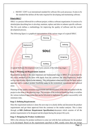
The following figure is a graphical representation of the various stages of a typical SDLC.
A typical Software Development Life Cycle consists of the following stages −
Stage 1: Planning and Requirement Analysis
Requirement analysis is the most important and fundamental stage in SDLC. It is performed by
the senior members of the team with inputs from the customer, the sales department, market
surveys and domain experts in the industry. This information is then used to plan the basic project
approach and to conduct product feasibility study in the economical, operational and technical
areas.
Planning for the quality assurance requirements and identification of the risks associated with the
project is also done in the planning stage. The outcome of the technical feasibility study is to define
the various technical approaches that can be followed to implement the project successfully with
minimum risks.
Stage 2: Defining Requirements
Once the requirement analysis is done the next step is to clearly define and document the product
requirements and get them approved from the customer or the market analysts. This is done
through an SRS (Software Requirement Specification) document which consists of all the
product requirements to be designed and developed during the project life cycle.
Stage 3: Designing the Product Architecture
SRS is the reference for product architects to come out with the best architecture for the product
to be developed. Based on the requirements specified in SRS, usually more than one design
Page | 4
approach for the product architecture is proposed and documented in a DDS - Design Document
Specification.
This DDS is reviewed by all the important stakeholders and based on various parameters as risk
assessment, product robustness, design modularity, budget and time constraints, the best design
approach is selected for the product.
A design approach clearly defines all the architectural modules of the product along with its
communication and data flow representation with the external and third party modules (if any).
The internal design of all the modules of the proposed architecture should be clearly defined with
the minutest of the details in DDS.
Stage 4: Building or Developing the Product
In this stage of SDLC the actual development starts and the product is built. The programming
code is generated as per DDS during this stage. If the design is performed in a detailed and
organized manner, code generation can be accomplished without much hassle.
Developers must follow the coding guidelines defined by their organization and programming
tools like compilers, interpreters, debuggers, etc. are used to generate the code. Different high
level programming languages such as C, C++, Pascal, Java and PHP are used for coding. The
programming language is chosen with respect to the type of software being developed.
Stage 5: Testing the Product
This stage is usually a subset of all the stages as in the modern SDLC models, the testing activities
are mostly involved in all the stages of SDLC. However, this stage refers to the testing only stage
of the product where product defects are reported, tracked, fixed and retested, until the product
reaches the quality standards defined in the SRS.
Stage 6: Deployment in the Market and Maintenance
Once the product is tested and ready to be deployed it is released formally in the appropriate
market. Sometimes product deployment happens in stages as per the business strategy of that
organization. The product may first be released in a limited segment and tested in the real business
environment (UAT- User acceptance testing).
Then based on the feedback, the product may be released as it is or with suggested enhancements
in the targeting market segment. After the product is released in the market, its maintenance is
done for the existing customer base.
ObjectOrientedApproach
In the object-oriented approach, the focus is on capturing the structure and behavior of information
systems into small modules that combines both data and process. The main aim of Object Oriented
Design (OOD) is to improve the quality and productivity of system analysis and design by making
it more usable.
In analysis phase, OO models are used to fill the gap between problem and solution. It performs
Page | 5
well in situation where systems are undergoing continuous design, adaption, and maintenance. It
identifies the objects in problem domain, classifying them in terms of data and behavior.
The OO model is beneficial in the following ways −
• It facilitates changes in the system at low cost.
• It promotes the reuse of components.
• It simplifies the problem of integrating components to configure large system.
• It simplifies the design of distributed systems.
ElementsofObject-OrientedSystem
Let us go through the characteristics of OO System −
• Objects − An object is something that is exists within problem domain and can be
identified by data (attribute) or behavior. All tangible entities (student, patient) and some
intangible entities (bank account) are modeled as object.
• Attributes − They describe information about the object.
• Behavior − It specifies what the object can do. It defines the operation performed on
objects.
• Class − A class encapsulates the data and its behavior. Objects with similar meaning and
purpose grouped together as class.
• Methods − Methods determine the behavior of a class. They are nothing more than an
action that an object can perform.
• Message − A message is a function or procedure call from one object to another. They are
information sent to objects to trigger methods. Essentially, a message is a function or
procedure call from one object to another.
FeaturesofObject-OrientedSystem
An object-oriented system comes with several great features which are discussed below.
Encapsulation
Encapsulation is a process of information hiding. It is simply the combination of process and data
into a single entity. Data of an object is hidden from the rest of the system and available only
through the services of the class. It allows improvement or modification of methods used by
objects without affecting other parts of a system.
Abstraction
It is a process of taking or selecting necessary method and attributes to specify the object. It focuses
on essential characteristics of an object relative to perspective of user.
Page | 6
Relationships
All the classes in the system are related with each other. The objects do not exist in isolation; they
exist in relationship with other objects.
There are three types of object relationships −
• Aggregation − It indicates relationship between a whole and its parts.
• Association − In this, two classes are related or connected in some way such as one class
works with another to perform a task or one class acts upon other class.
• Generalization − The child class is based on parent class. It indicates that two classes are
similar but have some differences.
Inheritance
Inheritance is a great feature that allows to create sub-classes from an existing class by inheriting
the attributes and/or operations of existing classes.
Polymorphism and Dynamic Binding
Polymorphism is the ability to take on many different forms. It applies to both objects and
operations. A polymorphic object is one who true type hides within a super or parent class.
In polymorphic operation, the operation may be carried out differently by different classes of
objects. It allows us to manipulate objects of different classes by knowing only their common
properties.
StructuredApproachvs.Object-OrientedApproach
The following table explains how the object-oriented approach differs from the traditional
structured approach −
Structured Approach Object Oriented Approach
It works with Top-down approach. It works with Bottom-up approach.
Program is divided into number of sub
modules or functions.
Program is organized by having number of
classes and objects.
Function call is used. Message passing is used.
Software reuse is not possible. Reusability is possible.
Structured design programming usually left
until end phases.
Object oriented design programming done
concurrently with other phases.
Page | 7
Structured Design is more suitable for
offshoring.
It is suitable for in-house development.
It shows clear transition from design to
implementation.
Not so clear transition from design to
implementation.
It is suitable for real time system, embedded
system and projects where objects are not the
most useful level of abstraction.
It is suitable for most business applications,
game development projects, which are
expected to customize or extended.
DFD & E-R diagram model the data. Class diagram, sequence diagram, state
chart diagram, and use cases all contribute.
In this, projects can be managed easily due to
clearly identifiable phases.
In this approach, projects can be difficult to
manage due to uncertain transitions between
phases.
OBJECT-ORIENTED SYSTEMS DEVELOPMENT METHODOLOGY
Object-oriented development offers a different model from the traditional software development
approach, which is based on functions and procedures. In simplified terms, object-oriented systems
development is a way to develop software by building self-contained modules or objects that can
be easily replaced, modified, and reused.
In an object-oriented environment,
Software is a collection of discrete objects that encapsulate their data as well as the functionality
to model real-world "objects."
An object orientation yields important benefits to the practice of software construction
Each object has attributes (data) and methods (functions).
Objects are grouped into classes; in object-oriented terms, we discover and describe the classes
involved in the problem domain.
Everything is an object and each object is responsible for itself.
Example
Consider the Windows application needs Windows objects A Windows object is responsible for
things like opening, sizing, and closing itself. Frequently, when a window displays something, that
something also is an object (a chart, for example). A chart object is responsible for things like
maintaining its data and labels and even for drawing itself.
Object-oriented methods enable us to create sets of objects that works together
synergistically to produce software that better model their problem domains than similar systems
produced by traditional techniques. The systems are easier to adapt to changing requirements, easier
to maintain, more robust, and promote greater de-sign and code reuse. Object-oriented development
allows us to create modules of functionality.
Once objects are defined, it can be taken for granted that they will perform their desired
Page | 8
functions and you can seal them off in your mind like black boxes. Your attention as a programmer
shifts to what they do rather than how they do it.
Importance of Object Orientation
Higher level of abstraction
The object-oriented approach supports abstraction at the object level. Since objects encapsulate
both data (attributes) and functions (methods), they work at a higher level of abstraction. The
development can proceed at the object level and ignore the rest of the system for as long as
necessary. This makes designing, coding, testing, and maintaining the system much simpler.
Seamless transition among different phases of software development
The traditional approach to software development requires different styles and methodologies for
each step of the process. Moving from one phase to another requires a complex transition of
perspective between models that almost can be in different worlds. This transition not only can
slow the development process but also increases the size of the project and the chance for errors
introduced in moving from one language to another. The object-oriented approach, on the other
hand, essentially uses the same language to talk about analysis, design, programming, and database
design. This seamless approach reduces the level of complexity and redundancy and makes for
clearer, more robust system development.
Encouragement of good programming techniques
A class in an object-oriented system carefully delineates between its interfaces the routines and
attributes within a class are held together tightly. In a properly designed system, the classes will be
grouped into subsystems but remain independent; therefore, changing one class has no impact on
other classes, and so, the impact is minimized.
However, the object-oriented approach is not a panacea; nothing is magical here that will promote
perfect design or perfect code.
Promotion of reusability
Objects are reusable because they are modeled directly out of a real-world problem domain. Each
object stands by itself or within a small circle of peers (other objects). Within this framework, the
class does not concern itself with the rest of the system or how it is going to be used within a
particular system.
Object-OrientedProgramming
Object-oriented programming (OOP) is a programming paradigm based upon objects (having
both data and methods) that aims to incorporate the advantages of modularity and reusability.
Objects, which are usually instances of classes, are used to interact with one another to design
applications and computer programs.
The important features of object–oriented programming are −
• Bottom–up approach in program design
• Programs organized around objects, grouped in classes
• Focus on data with methods to operate upon object’s data
Page | 9
• Interaction between objects through functions
• Reusability of design through creation of new classes by adding features to existing
classes
Some examples of object-oriented programming languages are C++, Java, Smalltalk, Delphi, C#,
Perl, Python, Ruby, and PHP.
Object-OrientedDesign
Object–Oriented Design (OOD) involves implementation of the conceptual model produced
during object-oriented analysis. In OOD, concepts in the analysis model, which are
technology−independent, are mapped onto implementing classes, constraints are identified and
interfaces are designed, resulting in a model for the solution domain, i.e., a detailed description
of how the system is to be built on concrete technologies.
The implementation details generally include −
• Restructuring the class data (if necessary),
• Implementation of methods, i.e., internal data structures and algorithms,
• Implementation of control, and
• Implementation of associations.
The Booch method
Grady Booch has defined object-oriented design as “a method of design encompassing the process
of object-oriented decomposition and a notation for depicting both logical and physical as well as
static and dynamic models of the system under design”.
Booch's methodology has its primary strength in the object system design. Grady Booch has
included in his methodology a requirements analysis that is similar to a traditional requirements
analysis, as well as a domain analysis phase.
Booch's object system design method has four parts, the logical structure design where the class
hierarchies are defined, the physical structure diagram where the object methods are described.
In addition, Booch defines the dynamics of classes in a fashion very similar to the Rumbaugh
method, as well as an analysis of the dynamics of object instances, where he describes how an
object may change state.
Grady Booch has defined object–oriented programming as “a method of implementation in which
programs are organized as cooperative collections of objects, each of which represents an instance
of some class, and whose classes are all members of a hierarchy of classes united via inheritance
relationships”.
Page | 10
Object-OrientedAnalysis
Object–Oriented Analysis (OOA) is the procedure of identifying software engineering
requirements and developing software specifications in terms of a software system’s object model,
which comprises of interacting objects.
The main difference between object-oriented analysis and other forms of analysis is that in object-
oriented approach, requirements are organized around objects, which integrate both data and
functions. They are modeled after real-world objects that the system interacts with. In traditional
analysis methodologies, the two aspects - functions and data - are considered separately.
Grady Booch has defined OOA as, “Object-oriented analysis is a method of analysis that
examines requirements from the perspective of the classes and objects found in the vocabulary of
the problem domain”.
The primary tasks in object-oriented analysis (OOA) are −
• Identifying objects
• Organizing the objects by creating object model diagram
• Defining the internals of the objects, or object attributes
• Defining the behavior of the objects, i.e., object actions
• Describing how the objects interact
The common models used in OOA are use cases and object models.
The Coad-Yourdon method
Coad-Yourdon methodology has its primary strength in system analysis. Their methodology is
based on a technique called "SOSAS", which stands for the five steps that help make up the analysis
part of their methodology.
The first step in system analysis is called "Subjects", which are basically data flow diagrams for
objects. The second step is called "Objects", where they identify the object classes and the class
hierarchies. The third step is called "Structures", where they decompose structures into two types,
classification structures and composition structures.
Classification structures handle the inheritance connection between related classes, while
composition structures handle all of the other connections among classes. The next step in analysis
is called "Attributes", and the final step is called "Services", where all of the behaviors or methods
for each class are identified.
Following analysis, Coad and Yourdon define four parts that make up the design part of their
methodology. The steps of system design are:
• The problem domain component - This will define the classes that should be in the problem
domain.
• The human interaction component - These steps defines the interface classes between
objects.
• The task management component - This is where system-wide management classes are
identified.
Page | 11
• The data management component - This design step identifies the classes needed for
database access methods.
Object-Oriented Modeling (OOM)
Object-oriented modeling (OOM) is the construction of objects using a collection of objects that
contain stored values of the instance variables found within an object. Unlike models that are
record-oriented, object-oriented values are solely objects.
The object-oriented modeling approach creates the union of the application
and database development and transforms it into a unified data model and language environment.
Object-oriented modeling allows for object identification and communication while supporting
data abstraction, inheritance and encapsulation.
The Rumbaugh method
The Rumbaugh method is listed first because it is these authors favorite, and we find it a very
friendly and easy methodology.
For traditional system analyst's, the Rumbaugh's methodology is the closest to the traditional
approach to system analysis and design, and beginners will recognize familiar symbols and
techniques. The Rumbaugh methodology has its primary strength in object analysis but it also does
an excellent job with object design.
Rumbaugh has three deliverables to the object analysis phase; the Object model, the Dynamic
model, and the functional model. These three models are similar to traditional system analysis,
with the additions for the object model, including definitions of classes along with the classes
variables and behaviors.
The Rumbaugh object model is very much like an entity relationship diagram except that there are
now behaviors in the diagram and class hierarchies.
The dynamic model is a "state transition" diagram that shows how an entity changes from one state
to another state. The functional model is the equivalent of the familiar data flow diagrams from a
traditional systems analysis.
Object-Oriented Software Engineering – OOSE
Object-oriented software engineering (commonly known by acronym OOSE) is an object-
modeling language and methodology.
OOSE was developed by Ivar Jacobson in 1992 while at Objectory AB. It is the first object-
oriented design methodology to employ use cases to drive software design. It also uses other design
products similar to those used by Object-modeling technique.
The tool Objectory was created by the team at Objectory AB to implement the OOSE methodology.
After success in the marketplace, other tool vendors also supported OOSE.
After Rational Software bought Objectory AB, the OOSE notation, methodology, and tools became
superseded.
• As one of the primary sources of the Unified Modeling Language (UML), concepts and
notation from OOSE have been incorporated into UML.
• The methodology part of OOSE has since evolved into the Rational Unified Process (RUP).
• The OOSE tools have been replaced by tools supporting UML and RUP.
OOSE has been largely replaced by the UML notation and by the RUP methodology.
Page | 12
Main Issues:
1. Software products can get very complex.
2. High-quality results are expected.
3. The development team can be large and distributed.
4. Most projects add functionality to an existing product.
The Ivar Jacobson Method:
Object-Oriented Software Engineering (OOSE) is a software design technique that is used in
software design in object-oriented programming.
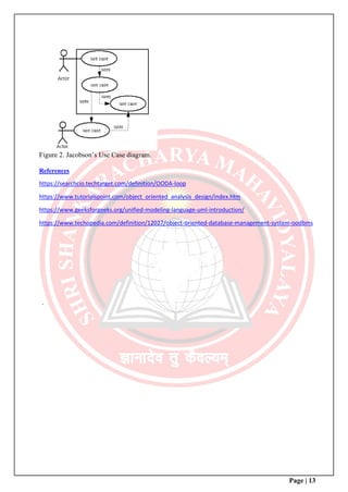
OOSE is developed by Ivar Jacobson in 1992. OOSE is the first object-oriented design
methodology that employs use cases in software design. OOSE is one of the precursors of the
Unified Modeling Language (UML), such as Booch and OMT.
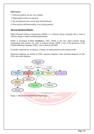
It includes requirements, an analysis, a design, an implementation and a testing model.
Interaction diagrams are similar to UML's sequence diagrams. State transition diagrams are like
UML state chart diagrams.
Figure 1. Object-Oriented Software Engineering.
Page | 13
Figure 2. Jacobson’s Use Case diagram.
References
https://searchcio.techtarget.com/definition/OODA-loop
https://www.tutorialspoint.com/object_oriented_analysis_design/index.htm
https://www.geeksforgeeks.org/unified-modeling-language-uml-introduction/
https://www.techopedia.com/definition/12027/object-oriented-database-management-system-oodbms
.
Page | 14

More Related Content

What's hot

Curve and text clipping
Curve and text clippingCurve and text clipping
Curve and text clippingArvind Kumar
 
Object Oriented Approach for Software Development
Object Oriented Approach for Software DevelopmentObject Oriented Approach for Software Development
Object Oriented Approach for Software DevelopmentRishabh Soni
 
3 d viewing projection
3 d viewing  projection3 d viewing  projection
3 d viewing projectionPooja Dixit
 
Component and Deployment Diagram - Brief Overview
Component and Deployment Diagram - Brief OverviewComponent and Deployment Diagram - Brief Overview
Component and Deployment Diagram - Brief OverviewRajiv Kumar
 
Raster scan system & random scan system
Raster scan system & random scan systemRaster scan system & random scan system
Raster scan system & random scan systemshalinikarunakaran1
 
CS8494 SOFTWARE ENGINEERING Unit-3
CS8494 SOFTWARE ENGINEERING Unit-3CS8494 SOFTWARE ENGINEERING Unit-3
CS8494 SOFTWARE ENGINEERING Unit-3SIMONTHOMAS S
 
Object Oriented Analysis (Coad-Yourdon)
Object Oriented Analysis (Coad-Yourdon)Object Oriented Analysis (Coad-Yourdon)
Object Oriented Analysis (Coad-Yourdon)Subash Khatiwada
 
Attributes of output primitive(line attributes)
Attributes of output primitive(line attributes)Attributes of output primitive(line attributes)
Attributes of output primitive(line attributes)shalinikarunakaran1
 
Computer graphics iv unit
Computer graphics iv unitComputer graphics iv unit
Computer graphics iv unitaravindangc
 
Design concept -Software Engineering
Design concept -Software EngineeringDesign concept -Software Engineering
Design concept -Software EngineeringVarsha Ajith
 
Pressman ch-11-component-level-design
Pressman ch-11-component-level-designPressman ch-11-component-level-design
Pressman ch-11-component-level-designOliver Cheng
 
Unit 1( modelling concepts & class modeling)
Unit  1( modelling concepts & class modeling)Unit  1( modelling concepts & class modeling)
Unit 1( modelling concepts & class modeling)Manoj Reddy
 
Object oriented methodologies
Object oriented methodologiesObject oriented methodologies
Object oriented methodologiesnaina-rani
 
OOAD UNIT I UML DIAGRAMS
OOAD UNIT I UML DIAGRAMSOOAD UNIT I UML DIAGRAMS
OOAD UNIT I UML DIAGRAMSMikel Raj
 

What's hot (20)

Depth Buffer Method
Depth Buffer MethodDepth Buffer Method
Depth Buffer Method
 
Clipping
ClippingClipping
Clipping
 
Curve and text clipping
Curve and text clippingCurve and text clipping
Curve and text clipping
 
Object Oriented Design
Object Oriented DesignObject Oriented Design
Object Oriented Design
 
Ooad unit – 1 introduction
Ooad unit – 1 introductionOoad unit – 1 introduction
Ooad unit – 1 introduction
 
Object Oriented Approach for Software Development
Object Oriented Approach for Software DevelopmentObject Oriented Approach for Software Development
Object Oriented Approach for Software Development
 
3 d viewing projection
3 d viewing  projection3 d viewing  projection
3 d viewing projection
 
Component and Deployment Diagram - Brief Overview
Component and Deployment Diagram - Brief OverviewComponent and Deployment Diagram - Brief Overview
Component and Deployment Diagram - Brief Overview
 
Raster scan system & random scan system
Raster scan system & random scan systemRaster scan system & random scan system
Raster scan system & random scan system
 
CS8494 SOFTWARE ENGINEERING Unit-3
CS8494 SOFTWARE ENGINEERING Unit-3CS8494 SOFTWARE ENGINEERING Unit-3
CS8494 SOFTWARE ENGINEERING Unit-3
 
Object Oriented Analysis and Design
Object Oriented Analysis and DesignObject Oriented Analysis and Design
Object Oriented Analysis and Design
 
Object Oriented Analysis (Coad-Yourdon)
Object Oriented Analysis (Coad-Yourdon)Object Oriented Analysis (Coad-Yourdon)
Object Oriented Analysis (Coad-Yourdon)
 
Attributes of output primitive(line attributes)
Attributes of output primitive(line attributes)Attributes of output primitive(line attributes)
Attributes of output primitive(line attributes)
 
Computer graphics iv unit
Computer graphics iv unitComputer graphics iv unit
Computer graphics iv unit
 
Design concept -Software Engineering
Design concept -Software EngineeringDesign concept -Software Engineering
Design concept -Software Engineering
 
Pressman ch-11-component-level-design
Pressman ch-11-component-level-designPressman ch-11-component-level-design
Pressman ch-11-component-level-design
 
Unit 1( modelling concepts & class modeling)
Unit  1( modelling concepts & class modeling)Unit  1( modelling concepts & class modeling)
Unit 1( modelling concepts & class modeling)
 
3D Display
3D Display3D Display
3D Display
 
Object oriented methodologies
Object oriented methodologiesObject oriented methodologies
Object oriented methodologies
 
OOAD UNIT I UML DIAGRAMS
OOAD UNIT I UML DIAGRAMSOOAD UNIT I UML DIAGRAMS
OOAD UNIT I UML DIAGRAMS
 

Similar to Object oriented analysis and design unit- i

1. object oriented concepts & principles
1. object oriented concepts & principles 1. object oriented concepts & principles
1. object oriented concepts & principles poonam bora
 
Health Informatics- Module 2-Chapter 1.pptx
Health Informatics- Module 2-Chapter 1.pptxHealth Informatics- Module 2-Chapter 1.pptx
Health Informatics- Module 2-Chapter 1.pptxArti Parab Academics
 
system development life cycle
system development life cyclesystem development life cycle
system development life cycleSuhleemAhmd
 
System Development Life_IntroductionCycle.pdf
System Development Life_IntroductionCycle.pdfSystem Development Life_IntroductionCycle.pdf
System Development Life_IntroductionCycle.pdfpncitechnologies
 
Report on SOFTWARE DEVELOPMENT LIFE CYCLE SDLC
Report on SOFTWARE DEVELOPMENT LIFE CYCLE SDLC Report on SOFTWARE DEVELOPMENT LIFE CYCLE SDLC
Report on SOFTWARE DEVELOPMENT LIFE CYCLE SDLC Neetu Marwah
 
Explore the System Development Life Cycle and Phases
Explore the System Development Life Cycle and PhasesExplore the System Development Life Cycle and Phases
Explore the System Development Life Cycle and PhasesInexture Solutions
 
mis ch2.pptx
mis ch2.pptxmis ch2.pptx
mis ch2.pptxTeshome48
 
Software testing and introduction to quality
Software testing and introduction to qualitySoftware testing and introduction to quality
Software testing and introduction to qualityDhanashriAmbre
 
Overview Of System Development Life Cycle (SDLC)
Overview Of System Development Life Cycle (SDLC)Overview Of System Development Life Cycle (SDLC)
Overview Of System Development Life Cycle (SDLC)Nicole Savoie
 
System Analysis and Design (Health Informatics)
System Analysis and Design (Health Informatics)System Analysis and Design (Health Informatics)
System Analysis and Design (Health Informatics)Zulfiquer Ahmed Amin
 
System Development Life Cycle part3
System Development Life Cycle part3System Development Life Cycle part3
System Development Life Cycle part3DrMohammed Qassim
 
System analysis and design Part2
System analysis and design Part2System analysis and design Part2
System analysis and design Part2Joel Briza
 
Social Media Site User Management System Class 12th Informatics Practices Pyt...
Social Media Site User Management System Class 12th Informatics Practices Pyt...Social Media Site User Management System Class 12th Informatics Practices Pyt...
Social Media Site User Management System Class 12th Informatics Practices Pyt...deboshreechatterjee2
 
Development of information system chap 2
Development of information system chap 2Development of information system chap 2
Development of information system chap 2amanuelayde1
 

Similar to Object oriented analysis and design unit- i (20)

1. object oriented concepts & principles
1. object oriented concepts & principles 1. object oriented concepts & principles
1. object oriented concepts & principles
 
Health Informatics- Module 2-Chapter 1.pptx
Health Informatics- Module 2-Chapter 1.pptxHealth Informatics- Module 2-Chapter 1.pptx
Health Informatics- Module 2-Chapter 1.pptx
 
system development life cycle
system development life cyclesystem development life cycle
system development life cycle
 
Sdlc1
Sdlc1Sdlc1
Sdlc1
 
System Development Life_IntroductionCycle.pdf
System Development Life_IntroductionCycle.pdfSystem Development Life_IntroductionCycle.pdf
System Development Life_IntroductionCycle.pdf
 
Report on SOFTWARE DEVELOPMENT LIFE CYCLE SDLC
Report on SOFTWARE DEVELOPMENT LIFE CYCLE SDLC Report on SOFTWARE DEVELOPMENT LIFE CYCLE SDLC
Report on SOFTWARE DEVELOPMENT LIFE CYCLE SDLC
 
Explore the System Development Life Cycle and Phases
Explore the System Development Life Cycle and PhasesExplore the System Development Life Cycle and Phases
Explore the System Development Life Cycle and Phases
 
software engineering
software engineering software engineering
software engineering
 
Week 10
Week 10Week 10
Week 10
 
Week 10
Week 10Week 10
Week 10
 
mis ch2.pptx
mis ch2.pptxmis ch2.pptx
mis ch2.pptx
 
Software testing and introduction to quality
Software testing and introduction to qualitySoftware testing and introduction to quality
Software testing and introduction to quality
 
Overview Of System Development Life Cycle (SDLC)
Overview Of System Development Life Cycle (SDLC)Overview Of System Development Life Cycle (SDLC)
Overview Of System Development Life Cycle (SDLC)
 
System Analysis and Design (Health Informatics)
System Analysis and Design (Health Informatics)System Analysis and Design (Health Informatics)
System Analysis and Design (Health Informatics)
 
System Development Life Cycle part3
System Development Life Cycle part3System Development Life Cycle part3
System Development Life Cycle part3
 
System analysis and design Part2
System analysis and design Part2System analysis and design Part2
System analysis and design Part2
 
4 sdlc and stlc
4 sdlc and stlc4 sdlc and stlc
4 sdlc and stlc
 
Social Media Site User Management System Class 12th Informatics Practices Pyt...
Social Media Site User Management System Class 12th Informatics Practices Pyt...Social Media Site User Management System Class 12th Informatics Practices Pyt...
Social Media Site User Management System Class 12th Informatics Practices Pyt...
 
SE notes by k. adisesha
SE notes by k. adiseshaSE notes by k. adisesha
SE notes by k. adisesha
 
Development of information system chap 2
Development of information system chap 2Development of information system chap 2
Development of information system chap 2
 

More from Shri Shankaracharya College, Bhilai,Junwani

More from Shri Shankaracharya College, Bhilai,Junwani (20)

Environment Economics &Ethics invisible hand & Malthusian theory
Environment Economics &Ethics invisible hand & Malthusian theoryEnvironment Economics &Ethics invisible hand & Malthusian theory
Environment Economics &Ethics invisible hand & Malthusian theory
 
Azadi ka amrut mahotsav, Mahilayon ka yogdan swatantrata Sangram mein
Azadi ka amrut mahotsav, Mahilayon ka yogdan swatantrata Sangram meinAzadi ka amrut mahotsav, Mahilayon ka yogdan swatantrata Sangram mein
Azadi ka amrut mahotsav, Mahilayon ka yogdan swatantrata Sangram mein
 
B.ed 1,scientific temper
B.ed 1,scientific temperB.ed 1,scientific temper
B.ed 1,scientific temper
 
Aims and objectives of bio. sci. 14 9-20
Aims and objectives of bio. sci. 14 9-20Aims and objectives of bio. sci. 14 9-20
Aims and objectives of bio. sci. 14 9-20
 
Ict application in bio.sc.24 9
Ict application in bio.sc.24 9Ict application in bio.sc.24 9
Ict application in bio.sc.24 9
 
Runges kutta method
Runges kutta methodRunges kutta method
Runges kutta method
 
Isolation & preservation of culture of microorganism
Isolation & preservation of  culture of microorganismIsolation & preservation of  culture of microorganism
Isolation & preservation of culture of microorganism
 
Learners understanding,unit 1, 15-9-20
Learners understanding,unit 1, 15-9-20Learners understanding,unit 1, 15-9-20
Learners understanding,unit 1, 15-9-20
 
Basics concept of physical chemistry
Basics concept of physical chemistryBasics concept of physical chemistry
Basics concept of physical chemistry
 
equilibrium of Firm
equilibrium  of Firmequilibrium  of Firm
equilibrium of Firm
 
indifference curve
 indifference curve indifference curve
indifference curve
 
Equilibrium
  Equilibrium  Equilibrium
Equilibrium
 
Crystal field theory
Crystal field theoryCrystal field theory
Crystal field theory
 
Utility
UtilityUtility
Utility
 
New economic reform
New economic reform New economic reform
New economic reform
 
Iso product Curve
Iso product CurveIso product Curve
Iso product Curve
 
Malnutrition
MalnutritionMalnutrition
Malnutrition
 
Demand theory
Demand theoryDemand theory
Demand theory
 
Land reform
Land reformLand reform
Land reform
 
Isomerism
IsomerismIsomerism
Isomerism
 

Recently uploaded

Selaginella: features, morphology ,anatomy and reproduction.
Selaginella: features, morphology ,anatomy and reproduction.Selaginella: features, morphology ,anatomy and reproduction.
Selaginella: features, morphology ,anatomy and reproduction.Silpa
 
(May 9, 2024) Enhanced Ultrafast Vector Flow Imaging (VFI) Using Multi-Angle ...
(May 9, 2024) Enhanced Ultrafast Vector Flow Imaging (VFI) Using Multi-Angle ...(May 9, 2024) Enhanced Ultrafast Vector Flow Imaging (VFI) Using Multi-Angle ...
(May 9, 2024) Enhanced Ultrafast Vector Flow Imaging (VFI) Using Multi-Angle ...Scintica Instrumentation
 
Stages in the normal growth curve
Stages in the normal growth curveStages in the normal growth curve
Stages in the normal growth curveAreesha Ahmad
 
Conjugation, transduction and transformation
Conjugation, transduction and transformationConjugation, transduction and transformation
Conjugation, transduction and transformationAreesha Ahmad
 
GBSN - Microbiology (Unit 1)
GBSN - Microbiology (Unit 1)GBSN - Microbiology (Unit 1)
GBSN - Microbiology (Unit 1)Areesha Ahmad
 
GBSN - Microbiology (Unit 3)
GBSN - Microbiology (Unit 3)GBSN - Microbiology (Unit 3)
GBSN - Microbiology (Unit 3)Areesha Ahmad
 
Porella : features, morphology, anatomy, reproduction etc.
Porella : features, morphology, anatomy, reproduction etc.Porella : features, morphology, anatomy, reproduction etc.
Porella : features, morphology, anatomy, reproduction etc.Silpa
 
Molecular markers- RFLP, RAPD, AFLP, SNP etc.
Molecular markers- RFLP, RAPD, AFLP, SNP etc.Molecular markers- RFLP, RAPD, AFLP, SNP etc.
Molecular markers- RFLP, RAPD, AFLP, SNP etc.Silpa
 
Call Girls Ahmedabad +917728919243 call me Independent Escort Service
Call Girls Ahmedabad +917728919243 call me Independent Escort ServiceCall Girls Ahmedabad +917728919243 call me Independent Escort Service
Call Girls Ahmedabad +917728919243 call me Independent Escort Serviceshivanisharma5244
 
Introduction of DNA analysis in Forensic's .pptx
Introduction of DNA analysis in Forensic's .pptxIntroduction of DNA analysis in Forensic's .pptx
Introduction of DNA analysis in Forensic's .pptxrohankumarsinghrore1
 
FAIRSpectra - Enabling the FAIRification of Spectroscopy and Spectrometry
FAIRSpectra - Enabling the FAIRification of Spectroscopy and SpectrometryFAIRSpectra - Enabling the FAIRification of Spectroscopy and Spectrometry
FAIRSpectra - Enabling the FAIRification of Spectroscopy and SpectrometryAlex Henderson
 
COMPUTING ANTI-DERIVATIVES (Integration by SUBSTITUTION)
COMPUTING ANTI-DERIVATIVES(Integration by SUBSTITUTION)COMPUTING ANTI-DERIVATIVES(Integration by SUBSTITUTION)
COMPUTING ANTI-DERIVATIVES (Integration by SUBSTITUTION)AkefAfaneh2
 
Use of mutants in understanding seedling development.pptx
Use of mutants in understanding seedling development.pptxUse of mutants in understanding seedling development.pptx
Use of mutants in understanding seedling development.pptxRenuJangid3
 
POGONATUM : morphology, anatomy, reproduction etc.
POGONATUM : morphology, anatomy, reproduction etc.POGONATUM : morphology, anatomy, reproduction etc.
POGONATUM : morphology, anatomy, reproduction etc.Silpa
 
development of diagnostic enzyme assay to detect leuser virus
development of diagnostic enzyme assay to detect leuser virusdevelopment of diagnostic enzyme assay to detect leuser virus
development of diagnostic enzyme assay to detect leuser virusNazaninKarimi6
 
Zoology 5th semester notes( Sumit_yadav).pdf
Zoology 5th semester notes( Sumit_yadav).pdfZoology 5th semester notes( Sumit_yadav).pdf
Zoology 5th semester notes( Sumit_yadav).pdfSumit Kumar yadav
 
Bacterial Identification and Classifications
Bacterial Identification and ClassificationsBacterial Identification and Classifications
Bacterial Identification and ClassificationsAreesha Ahmad
 

Recently uploaded (20)

Selaginella: features, morphology ,anatomy and reproduction.
Selaginella: features, morphology ,anatomy and reproduction.Selaginella: features, morphology ,anatomy and reproduction.
Selaginella: features, morphology ,anatomy and reproduction.
 
(May 9, 2024) Enhanced Ultrafast Vector Flow Imaging (VFI) Using Multi-Angle ...
(May 9, 2024) Enhanced Ultrafast Vector Flow Imaging (VFI) Using Multi-Angle ...(May 9, 2024) Enhanced Ultrafast Vector Flow Imaging (VFI) Using Multi-Angle ...
(May 9, 2024) Enhanced Ultrafast Vector Flow Imaging (VFI) Using Multi-Angle ...
 
Stages in the normal growth curve
Stages in the normal growth curveStages in the normal growth curve
Stages in the normal growth curve
 
Conjugation, transduction and transformation
Conjugation, transduction and transformationConjugation, transduction and transformation
Conjugation, transduction and transformation
 
GBSN - Microbiology (Unit 1)
GBSN - Microbiology (Unit 1)GBSN - Microbiology (Unit 1)
GBSN - Microbiology (Unit 1)
 
GBSN - Microbiology (Unit 3)
GBSN - Microbiology (Unit 3)GBSN - Microbiology (Unit 3)
GBSN - Microbiology (Unit 3)
 
Clean In Place(CIP).pptx .
Clean In Place(CIP).pptx                 .Clean In Place(CIP).pptx                 .
Clean In Place(CIP).pptx .
 
Site Acceptance Test .
Site Acceptance Test                    .Site Acceptance Test                    .
Site Acceptance Test .
 
Porella : features, morphology, anatomy, reproduction etc.
Porella : features, morphology, anatomy, reproduction etc.Porella : features, morphology, anatomy, reproduction etc.
Porella : features, morphology, anatomy, reproduction etc.
 
Molecular markers- RFLP, RAPD, AFLP, SNP etc.
Molecular markers- RFLP, RAPD, AFLP, SNP etc.Molecular markers- RFLP, RAPD, AFLP, SNP etc.
Molecular markers- RFLP, RAPD, AFLP, SNP etc.
 
Call Girls Ahmedabad +917728919243 call me Independent Escort Service
Call Girls Ahmedabad +917728919243 call me Independent Escort ServiceCall Girls Ahmedabad +917728919243 call me Independent Escort Service
Call Girls Ahmedabad +917728919243 call me Independent Escort Service
 
Introduction of DNA analysis in Forensic's .pptx
Introduction of DNA analysis in Forensic's .pptxIntroduction of DNA analysis in Forensic's .pptx
Introduction of DNA analysis in Forensic's .pptx
 
FAIRSpectra - Enabling the FAIRification of Spectroscopy and Spectrometry
FAIRSpectra - Enabling the FAIRification of Spectroscopy and SpectrometryFAIRSpectra - Enabling the FAIRification of Spectroscopy and Spectrometry
FAIRSpectra - Enabling the FAIRification of Spectroscopy and Spectrometry
 
+971581248768>> SAFE AND ORIGINAL ABORTION PILLS FOR SALE IN DUBAI AND ABUDHA...
+971581248768>> SAFE AND ORIGINAL ABORTION PILLS FOR SALE IN DUBAI AND ABUDHA...+971581248768>> SAFE AND ORIGINAL ABORTION PILLS FOR SALE IN DUBAI AND ABUDHA...
+971581248768>> SAFE AND ORIGINAL ABORTION PILLS FOR SALE IN DUBAI AND ABUDHA...
 
COMPUTING ANTI-DERIVATIVES (Integration by SUBSTITUTION)
COMPUTING ANTI-DERIVATIVES(Integration by SUBSTITUTION)COMPUTING ANTI-DERIVATIVES(Integration by SUBSTITUTION)
COMPUTING ANTI-DERIVATIVES (Integration by SUBSTITUTION)
 
Use of mutants in understanding seedling development.pptx
Use of mutants in understanding seedling development.pptxUse of mutants in understanding seedling development.pptx
Use of mutants in understanding seedling development.pptx
 
POGONATUM : morphology, anatomy, reproduction etc.
POGONATUM : morphology, anatomy, reproduction etc.POGONATUM : morphology, anatomy, reproduction etc.
POGONATUM : morphology, anatomy, reproduction etc.
 
development of diagnostic enzyme assay to detect leuser virus
development of diagnostic enzyme assay to detect leuser virusdevelopment of diagnostic enzyme assay to detect leuser virus
development of diagnostic enzyme assay to detect leuser virus
 
Zoology 5th semester notes( Sumit_yadav).pdf
Zoology 5th semester notes( Sumit_yadav).pdfZoology 5th semester notes( Sumit_yadav).pdf
Zoology 5th semester notes( Sumit_yadav).pdf
 
Bacterial Identification and Classifications
Bacterial Identification and ClassificationsBacterial Identification and Classifications
Bacterial Identification and Classifications
 

Object oriented analysis and design unit- i

  • 1. Page | 1 Object Oriented Analysis and Design M.Sc. Computer Science III Semester MS. Arati Singh Department of Computer Science Shri Shankaracharya Mahavidyalaya Junwani Bhilai
  • 2. Page | 2 UNIT-I INTRODUCTION: Software development Software development is dynamic and always undergoing major change. The methods and tools will differ significantly from those currently in use. We can anticipate which methods and tools are going to succeed, but we cannot predict the future. Today a vast number of tools and methodologies are available for systems development. Systems development refers to all activities that go into producing an information systems solution. Systems development activities consists of Systems analysis Modeling, Design Implementation, testing Maintenance A software development methodology is a series of processes leads to the development of an application. The software processes describe how the work is to be carried out to achieve the original goal based on the system requirements. The software development process will continue to exist as long as the development system is in operation. Object-oriented systems development methods differ from traditional development techniques in that the traditional techniques view software as a collection of programs (or functions) and isolated data. A program can be defined as Algorithms + Data Structures = Programs: “A software system is a set of mechanisms for performing certain action on certain data.” The main distinction between traditional system development methodologies and newer object-oriented methodologies depends on their primary focus: traditional approach - focuses on the functions of the system object-oriented systems development - Centers on the object, which combines data and functionality. Software Development Life Cycle (SDLC) Software Development Life Cycle (SDLC) is a process used by the software industry to design, develop and test high quality software. The SDLC aims to produce a high-quality software that meets or exceeds customer expectations, reaches completion within times and cost estimates. • SDLC is the acronym of Software Development Life Cycle. • It is also called as Software Development Process. • SDLC is a framework defining tasks performed at each step in the software development process.
  • 3. Page | 3 • ISO/IEC 12207 is an international standard for software life-cycle processes. It aims to be the standard that defines all the tasks required for developing and maintaining software. WhatisSDLC? SDLC is a process followed for a software project, within a software organization. It consists of a detailed plan describing how to develop, maintain, replace and alter or enhance specific software. The life cycle defines a methodology for improving the quality of software and the overall development process. The following figure is a graphical representation of the various stages of a typical SDLC. A typical Software Development Life Cycle consists of the following stages − Stage 1: Planning and Requirement Analysis Requirement analysis is the most important and fundamental stage in SDLC. It is performed by the senior members of the team with inputs from the customer, the sales department, market surveys and domain experts in the industry. This information is then used to plan the basic project approach and to conduct product feasibility study in the economical, operational and technical areas. Planning for the quality assurance requirements and identification of the risks associated with the project is also done in the planning stage. The outcome of the technical feasibility study is to define the various technical approaches that can be followed to implement the project successfully with minimum risks. Stage 2: Defining Requirements Once the requirement analysis is done the next step is to clearly define and document the product requirements and get them approved from the customer or the market analysts. This is done through an SRS (Software Requirement Specification) document which consists of all the product requirements to be designed and developed during the project life cycle. Stage 3: Designing the Product Architecture SRS is the reference for product architects to come out with the best architecture for the product to be developed. Based on the requirements specified in SRS, usually more than one design
  • 4. Page | 4 approach for the product architecture is proposed and documented in a DDS - Design Document Specification. This DDS is reviewed by all the important stakeholders and based on various parameters as risk assessment, product robustness, design modularity, budget and time constraints, the best design approach is selected for the product. A design approach clearly defines all the architectural modules of the product along with its communication and data flow representation with the external and third party modules (if any). The internal design of all the modules of the proposed architecture should be clearly defined with the minutest of the details in DDS. Stage 4: Building or Developing the Product In this stage of SDLC the actual development starts and the product is built. The programming code is generated as per DDS during this stage. If the design is performed in a detailed and organized manner, code generation can be accomplished without much hassle. Developers must follow the coding guidelines defined by their organization and programming tools like compilers, interpreters, debuggers, etc. are used to generate the code. Different high level programming languages such as C, C++, Pascal, Java and PHP are used for coding. The programming language is chosen with respect to the type of software being developed. Stage 5: Testing the Product This stage is usually a subset of all the stages as in the modern SDLC models, the testing activities are mostly involved in all the stages of SDLC. However, this stage refers to the testing only stage of the product where product defects are reported, tracked, fixed and retested, until the product reaches the quality standards defined in the SRS. Stage 6: Deployment in the Market and Maintenance Once the product is tested and ready to be deployed it is released formally in the appropriate market. Sometimes product deployment happens in stages as per the business strategy of that organization. The product may first be released in a limited segment and tested in the real business environment (UAT- User acceptance testing). Then based on the feedback, the product may be released as it is or with suggested enhancements in the targeting market segment. After the product is released in the market, its maintenance is done for the existing customer base. ObjectOrientedApproach In the object-oriented approach, the focus is on capturing the structure and behavior of information systems into small modules that combines both data and process. The main aim of Object Oriented Design (OOD) is to improve the quality and productivity of system analysis and design by making it more usable. In analysis phase, OO models are used to fill the gap between problem and solution. It performs
  • 5. Page | 5 well in situation where systems are undergoing continuous design, adaption, and maintenance. It identifies the objects in problem domain, classifying them in terms of data and behavior. The OO model is beneficial in the following ways − • It facilitates changes in the system at low cost. • It promotes the reuse of components. • It simplifies the problem of integrating components to configure large system. • It simplifies the design of distributed systems. ElementsofObject-OrientedSystem Let us go through the characteristics of OO System − • Objects − An object is something that is exists within problem domain and can be identified by data (attribute) or behavior. All tangible entities (student, patient) and some intangible entities (bank account) are modeled as object. • Attributes − They describe information about the object. • Behavior − It specifies what the object can do. It defines the operation performed on objects. • Class − A class encapsulates the data and its behavior. Objects with similar meaning and purpose grouped together as class. • Methods − Methods determine the behavior of a class. They are nothing more than an action that an object can perform. • Message − A message is a function or procedure call from one object to another. They are information sent to objects to trigger methods. Essentially, a message is a function or procedure call from one object to another. FeaturesofObject-OrientedSystem An object-oriented system comes with several great features which are discussed below. Encapsulation Encapsulation is a process of information hiding. It is simply the combination of process and data into a single entity. Data of an object is hidden from the rest of the system and available only through the services of the class. It allows improvement or modification of methods used by objects without affecting other parts of a system. Abstraction It is a process of taking or selecting necessary method and attributes to specify the object. It focuses on essential characteristics of an object relative to perspective of user.
  • 6. Page | 6 Relationships All the classes in the system are related with each other. The objects do not exist in isolation; they exist in relationship with other objects. There are three types of object relationships − • Aggregation − It indicates relationship between a whole and its parts. • Association − In this, two classes are related or connected in some way such as one class works with another to perform a task or one class acts upon other class. • Generalization − The child class is based on parent class. It indicates that two classes are similar but have some differences. Inheritance Inheritance is a great feature that allows to create sub-classes from an existing class by inheriting the attributes and/or operations of existing classes. Polymorphism and Dynamic Binding Polymorphism is the ability to take on many different forms. It applies to both objects and operations. A polymorphic object is one who true type hides within a super or parent class. In polymorphic operation, the operation may be carried out differently by different classes of objects. It allows us to manipulate objects of different classes by knowing only their common properties. StructuredApproachvs.Object-OrientedApproach The following table explains how the object-oriented approach differs from the traditional structured approach − Structured Approach Object Oriented Approach It works with Top-down approach. It works with Bottom-up approach. Program is divided into number of sub modules or functions. Program is organized by having number of classes and objects. Function call is used. Message passing is used. Software reuse is not possible. Reusability is possible. Structured design programming usually left until end phases. Object oriented design programming done concurrently with other phases.
  • 7. Page | 7 Structured Design is more suitable for offshoring. It is suitable for in-house development. It shows clear transition from design to implementation. Not so clear transition from design to implementation. It is suitable for real time system, embedded system and projects where objects are not the most useful level of abstraction. It is suitable for most business applications, game development projects, which are expected to customize or extended. DFD & E-R diagram model the data. Class diagram, sequence diagram, state chart diagram, and use cases all contribute. In this, projects can be managed easily due to clearly identifiable phases. In this approach, projects can be difficult to manage due to uncertain transitions between phases. OBJECT-ORIENTED SYSTEMS DEVELOPMENT METHODOLOGY Object-oriented development offers a different model from the traditional software development approach, which is based on functions and procedures. In simplified terms, object-oriented systems development is a way to develop software by building self-contained modules or objects that can be easily replaced, modified, and reused. In an object-oriented environment, Software is a collection of discrete objects that encapsulate their data as well as the functionality to model real-world "objects." An object orientation yields important benefits to the practice of software construction Each object has attributes (data) and methods (functions). Objects are grouped into classes; in object-oriented terms, we discover and describe the classes involved in the problem domain. Everything is an object and each object is responsible for itself. Example Consider the Windows application needs Windows objects A Windows object is responsible for things like opening, sizing, and closing itself. Frequently, when a window displays something, that something also is an object (a chart, for example). A chart object is responsible for things like maintaining its data and labels and even for drawing itself. Object-oriented methods enable us to create sets of objects that works together synergistically to produce software that better model their problem domains than similar systems produced by traditional techniques. The systems are easier to adapt to changing requirements, easier to maintain, more robust, and promote greater de-sign and code reuse. Object-oriented development allows us to create modules of functionality. Once objects are defined, it can be taken for granted that they will perform their desired
  • 8. Page | 8 functions and you can seal them off in your mind like black boxes. Your attention as a programmer shifts to what they do rather than how they do it. Importance of Object Orientation Higher level of abstraction The object-oriented approach supports abstraction at the object level. Since objects encapsulate both data (attributes) and functions (methods), they work at a higher level of abstraction. The development can proceed at the object level and ignore the rest of the system for as long as necessary. This makes designing, coding, testing, and maintaining the system much simpler. Seamless transition among different phases of software development The traditional approach to software development requires different styles and methodologies for each step of the process. Moving from one phase to another requires a complex transition of perspective between models that almost can be in different worlds. This transition not only can slow the development process but also increases the size of the project and the chance for errors introduced in moving from one language to another. The object-oriented approach, on the other hand, essentially uses the same language to talk about analysis, design, programming, and database design. This seamless approach reduces the level of complexity and redundancy and makes for clearer, more robust system development. Encouragement of good programming techniques A class in an object-oriented system carefully delineates between its interfaces the routines and attributes within a class are held together tightly. In a properly designed system, the classes will be grouped into subsystems but remain independent; therefore, changing one class has no impact on other classes, and so, the impact is minimized. However, the object-oriented approach is not a panacea; nothing is magical here that will promote perfect design or perfect code. Promotion of reusability Objects are reusable because they are modeled directly out of a real-world problem domain. Each object stands by itself or within a small circle of peers (other objects). Within this framework, the class does not concern itself with the rest of the system or how it is going to be used within a particular system. Object-OrientedProgramming Object-oriented programming (OOP) is a programming paradigm based upon objects (having both data and methods) that aims to incorporate the advantages of modularity and reusability. Objects, which are usually instances of classes, are used to interact with one another to design applications and computer programs. The important features of object–oriented programming are − • Bottom–up approach in program design • Programs organized around objects, grouped in classes • Focus on data with methods to operate upon object’s data
  • 9. Page | 9 • Interaction between objects through functions • Reusability of design through creation of new classes by adding features to existing classes Some examples of object-oriented programming languages are C++, Java, Smalltalk, Delphi, C#, Perl, Python, Ruby, and PHP. Object-OrientedDesign Object–Oriented Design (OOD) involves implementation of the conceptual model produced during object-oriented analysis. In OOD, concepts in the analysis model, which are technology−independent, are mapped onto implementing classes, constraints are identified and interfaces are designed, resulting in a model for the solution domain, i.e., a detailed description of how the system is to be built on concrete technologies. The implementation details generally include − • Restructuring the class data (if necessary), • Implementation of methods, i.e., internal data structures and algorithms, • Implementation of control, and • Implementation of associations. The Booch method Grady Booch has defined object-oriented design as “a method of design encompassing the process of object-oriented decomposition and a notation for depicting both logical and physical as well as static and dynamic models of the system under design”. Booch's methodology has its primary strength in the object system design. Grady Booch has included in his methodology a requirements analysis that is similar to a traditional requirements analysis, as well as a domain analysis phase. Booch's object system design method has four parts, the logical structure design where the class hierarchies are defined, the physical structure diagram where the object methods are described. In addition, Booch defines the dynamics of classes in a fashion very similar to the Rumbaugh method, as well as an analysis of the dynamics of object instances, where he describes how an object may change state. Grady Booch has defined object–oriented programming as “a method of implementation in which programs are organized as cooperative collections of objects, each of which represents an instance of some class, and whose classes are all members of a hierarchy of classes united via inheritance relationships”.
  • 10. Page | 10 Object-OrientedAnalysis Object–Oriented Analysis (OOA) is the procedure of identifying software engineering requirements and developing software specifications in terms of a software system’s object model, which comprises of interacting objects. The main difference between object-oriented analysis and other forms of analysis is that in object- oriented approach, requirements are organized around objects, which integrate both data and functions. They are modeled after real-world objects that the system interacts with. In traditional analysis methodologies, the two aspects - functions and data - are considered separately. Grady Booch has defined OOA as, “Object-oriented analysis is a method of analysis that examines requirements from the perspective of the classes and objects found in the vocabulary of the problem domain”. The primary tasks in object-oriented analysis (OOA) are − • Identifying objects • Organizing the objects by creating object model diagram • Defining the internals of the objects, or object attributes • Defining the behavior of the objects, i.e., object actions • Describing how the objects interact The common models used in OOA are use cases and object models. The Coad-Yourdon method Coad-Yourdon methodology has its primary strength in system analysis. Their methodology is based on a technique called "SOSAS", which stands for the five steps that help make up the analysis part of their methodology. The first step in system analysis is called "Subjects", which are basically data flow diagrams for objects. The second step is called "Objects", where they identify the object classes and the class hierarchies. The third step is called "Structures", where they decompose structures into two types, classification structures and composition structures. Classification structures handle the inheritance connection between related classes, while composition structures handle all of the other connections among classes. The next step in analysis is called "Attributes", and the final step is called "Services", where all of the behaviors or methods for each class are identified. Following analysis, Coad and Yourdon define four parts that make up the design part of their methodology. The steps of system design are: • The problem domain component - This will define the classes that should be in the problem domain. • The human interaction component - These steps defines the interface classes between objects. • The task management component - This is where system-wide management classes are identified.
  • 11. Page | 11 • The data management component - This design step identifies the classes needed for database access methods. Object-Oriented Modeling (OOM) Object-oriented modeling (OOM) is the construction of objects using a collection of objects that contain stored values of the instance variables found within an object. Unlike models that are record-oriented, object-oriented values are solely objects. The object-oriented modeling approach creates the union of the application and database development and transforms it into a unified data model and language environment. Object-oriented modeling allows for object identification and communication while supporting data abstraction, inheritance and encapsulation. The Rumbaugh method The Rumbaugh method is listed first because it is these authors favorite, and we find it a very friendly and easy methodology. For traditional system analyst's, the Rumbaugh's methodology is the closest to the traditional approach to system analysis and design, and beginners will recognize familiar symbols and techniques. The Rumbaugh methodology has its primary strength in object analysis but it also does an excellent job with object design. Rumbaugh has three deliverables to the object analysis phase; the Object model, the Dynamic model, and the functional model. These three models are similar to traditional system analysis, with the additions for the object model, including definitions of classes along with the classes variables and behaviors. The Rumbaugh object model is very much like an entity relationship diagram except that there are now behaviors in the diagram and class hierarchies. The dynamic model is a "state transition" diagram that shows how an entity changes from one state to another state. The functional model is the equivalent of the familiar data flow diagrams from a traditional systems analysis. Object-Oriented Software Engineering – OOSE Object-oriented software engineering (commonly known by acronym OOSE) is an object- modeling language and methodology. OOSE was developed by Ivar Jacobson in 1992 while at Objectory AB. It is the first object- oriented design methodology to employ use cases to drive software design. It also uses other design products similar to those used by Object-modeling technique. The tool Objectory was created by the team at Objectory AB to implement the OOSE methodology. After success in the marketplace, other tool vendors also supported OOSE. After Rational Software bought Objectory AB, the OOSE notation, methodology, and tools became superseded. • As one of the primary sources of the Unified Modeling Language (UML), concepts and notation from OOSE have been incorporated into UML. • The methodology part of OOSE has since evolved into the Rational Unified Process (RUP). • The OOSE tools have been replaced by tools supporting UML and RUP. OOSE has been largely replaced by the UML notation and by the RUP methodology.
  • 12. Page | 12 Main Issues: 1. Software products can get very complex. 2. High-quality results are expected. 3. The development team can be large and distributed. 4. Most projects add functionality to an existing product. The Ivar Jacobson Method: Object-Oriented Software Engineering (OOSE) is a software design technique that is used in software design in object-oriented programming. OOSE is developed by Ivar Jacobson in 1992. OOSE is the first object-oriented design methodology that employs use cases in software design. OOSE is one of the precursors of the Unified Modeling Language (UML), such as Booch and OMT. It includes requirements, an analysis, a design, an implementation and a testing model. Interaction diagrams are similar to UML's sequence diagrams. State transition diagrams are like UML state chart diagrams. Figure 1. Object-Oriented Software Engineering.
  • 13. Page | 13 Figure 2. Jacobson’s Use Case diagram. References https://searchcio.techtarget.com/definition/OODA-loop https://www.tutorialspoint.com/object_oriented_analysis_design/index.htm https://www.geeksforgeeks.org/unified-modeling-language-uml-introduction/ https://www.techopedia.com/definition/12027/object-oriented-database-management-system-oodbms .