Download to read offline


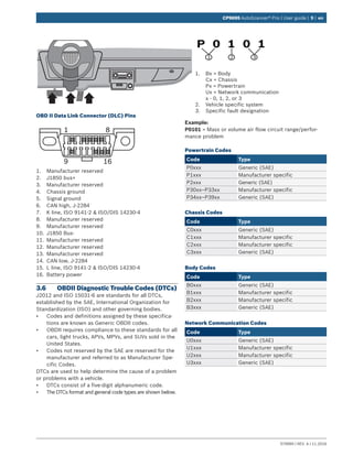


![en | 30 | User guide | CP9695 AutoScanner® Pro
579999 | REV. A | 11.2016
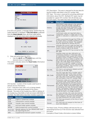
2. Observe while the scan tool validates PID MAP.
• PID MAP validation is the tool asking the vehicle
which PIDs are supported. See Appendix A for a
complete list of PIDs supported by the tool.
• Multiple PIDs may be sent if vehicle is equipped
with more than one computer module (for
example a powertrain control module [PCM]
and a transmission control module [TCM]). The
scan tool identifies them by their identification
names (ID) assigned by manufacturer (i.e. $10
or $1A).
• If one or more control module stops responding,
the scan tool displays a message.
–– If continuing, dashes will replace data in
right-hand column.
–– If NO is selected, then the scan tool
attempts to re-establish communication
with that module.
Validating PIDs
Please Wait
Waiting for vehicle to
respond
Validating PIDs
Please Wait
Validating PID List
PID 19/329
View Entire List
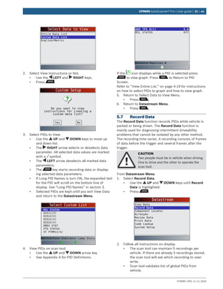
View Entire List shows all supported PID data for the
vehicle being tested
From Select Data to View menu:
1. Select Entire Data List.
• Use the UP and DOWN keys until Entire
Data List is highlighted.
• Press .
Select Data to View
Entire Data List
Custom Data List
English/Metric
2. View PIDs on scan tool.
• Use the UP and DOWN keys.
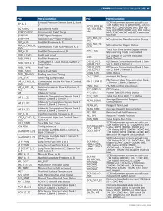
• See Appendix A for PID definitions.
ABS LOAD(%)
ABSLT TPS($01)
ABSLT TPS($07)
ACC POS D(%)
BARO PRS(”HG)
CALC LOAD(%)
CALC LOAD(%)
CAT TEMP11(°F)
CLR DIST(mi)
CLR DIST(mi)
0.0
6.3
6.3
0.0
29.2
0.0
0.0
73
499
513
Absolute Load Value
If Long PID Names is turned ON, the expanded text for
the PID will scroll on the bottom line of display. See
“Long PID Names” in section 3.
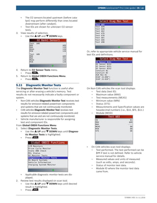
If the icon displays while a PID is selected press
to select PIDs to graph. A maximum of 2 PIDs can
be graphed.
Select PIDs to Graph
✓ABSLT TPS(%)
CALC LOAD(%)
COOLANT(°F)
ENG SPEED(RPM)
EQ RATIO11
IAT(°F)
IGN ADV(°)
LT FTRM1(%)
Throttle Position
• Use the RIGHT arrow key to select/deselect
PIDs. The highlighted PID from when was
pressed is already selected
• Use the LEFT arrow key to deselect all PIDs.
• Press to view graph of selected PIDs.
• When graphing two PIDs, use the UP and
DOWN keys to highlight the desired PID, which
will also display the appropriate scale.
• Press the key to pause the graph. Press
the key again to continue graphing.
• If the icon displays while a PID is selected
press to view graph.
3. Return to PID screen.
• Press .
4. Return to Select Data to View menu.
• Press .
5. Return to Datastream Menu.
• Press .
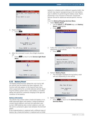
Custom List Select
The Custom Data List allows certain PIDs from the View
Entire Data List, such as those PIDs that apply to a
specific driveability symptom or system, to be selected.
From Select Data to View menu:
1. Select Custom List Select.
• Use the UP and DOWN keys until Custom
Data List is highlighted.
• Press .](https://image.slidesharecdn.com/actron9695-190116160352/85/Actron-CP9695-User-Manual-30-320.jpg)


The document is a user guide for the CP9695 Autoscanner® Pro, detailing safety precautions, equipment specifications, and procedures for using the scan tool. It emphasizes the importance of following safety instructions to prevent injury or equipment damage. The guide also provides information on diagnostic features, data management, and troubleshooting methods.


![Toyota Dashboard Warning Lights [FULL]](https://cdn.slidesharecdn.com/ss_thumbnails/toyota-warning-lights-211126044903-thumbnail.jpg?width=640&height=640&fit=bounds)


![Mazda Dashboard Warning Lights: Symbols and Meanings [FULL LIST]](https://cdn.slidesharecdn.com/ss_thumbnails/mazda-warning-lights-221021085358-dcf733ba-thumbnail.jpg?width=640&height=640&fit=bounds)


![Mini Cooper Dashboard Warning Lights: Symbols and Meanings [FULL LIST]](https://cdn.slidesharecdn.com/ss_thumbnails/mini-cooper-warning-lights-221021084944-27b65ebd-thumbnail.jpg?width=640&height=640&fit=bounds)


![[English Version]Maker-Ray Product Brochure V3 .pdf](https://cdn.slidesharecdn.com/ss_thumbnails/englishversionmaker-rayproductbrochurev3-260113094444-0156dbdc-thumbnail.jpg?width=640&height=640&fit=bounds)


