V20 training slides-Function introduction_LY_V8_EN.ppt
1.
Page 1 SINAMICSV20 Technical Training I DT MC M3BF
Structure
Function Introduction
Basic Function
Frequency Setpoint
Fixed Frequency
Command source
OFF Mode
Ramp time
Control mode
Voltage boost
PID
Braking Function
Advance Function
Flying start
Auto restart
Super Torque
Hammer Start
Blockage Clear
Frost Protection
Condensation Protection
Pump Staging Function
Sleep Mode
Parameter Cloning
Page 3 SINAMICSV20 Technical Training I DT MC M3BF
Frequency Setpoint
Description: Selects frequency setpoint source by parameter P1000
Related Parameter: P1074 BI: Disable additional setpoint / Disab.add.setp
For example: Set parameter P1000=23 (Fixed frequency + Analog setpoint )
Additional setpoint Main setpoint
Output
frequency
Run
command
Analog setpoint
Fixed frequency
Actual output
frequency
P1074
4.
Page 4 SINAMICSV20 Technical Training I DT MC M3BF
Fixed Frequency(1/2)
V20 supply two types of fixed frequency:
1. Direct Selection (P1016=1)
DI1 DI2 DI3 DI4 Frequency
1 0 0 0 FF1
0 1 0 0 FF2
0 0 1 0 FF3
0 0 0 1 FF4
1 1 1 1 FF1+FF2+FF3+FF4
Page 6 SINAMICSV20 Technical Training I DT MC M3BF
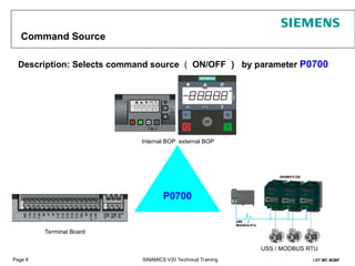
Command Source
Description: Selects command source ( ON/OFF ) by parameter P0700
Internal BOP external BOP
P0700
Terminal Board
USS / MODBUS RTU
7.
Page 7 SINAMICSV20 Technical Training I DT MC M3BF
Ramp-up Time & Ramp-down Time
Description
Set ramp-up time by P1120, set ramp-down time by P1121
Related Parameters
P1082 Max. Frequency
P1120 Ramp-up time
P1121 Ramp-down time
P1120
t
Output
Frequency
(Hz)
P1082
P1121
Setpoint
0
P1080
Min. Frequency
Attention: There is no relationship between
P1080 with Ramp time
8.
Page 8 SINAMICSV20 Technical Training I DT MC M3BF
Ramp Time set example
P1120
t
Output
Frequency
(Hz)
P1082
P1121
Setpoint
0
P1080
Min. Frequency
Set P1082( Max. frequency) as 50Hz, set P1120 as 10s. It means the ramp-up time from 0 to 50Hz is 10s.
Customer’s setpoint is 30Hz, so the ramp-up time from 0 to 30Hz is
9.
Page 9 SINAMICSV20 Technical Training I DT MC M3BF
Stop Mode
OFF1
The OFF1 command is strongly coupled to the ON command. When the ON command is
withdrawn, then OFF1 is directly activated. The motor stops by OFF1 with the time set in
parameter P1121 (ramp-down time).
OFF2
OFF3
The inverter pulses are immediately cancelled by the OFF2 command. Thus the motor coasts down
and it is not possible to stop in a controlled fashion 。
The braking characteristics of OFF3 are identical with those of OFF1 with the exception of the
autonomous OFF3 ramp-down time P1135.
10.
Page 10 SINAMICSV20 Technical Training I DT MC M3BF
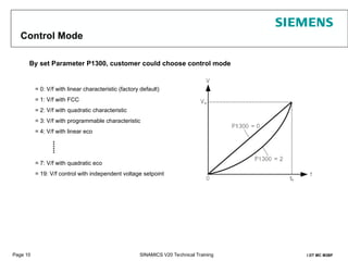
Control Mode
= 0: V/f with linear characteristic (factory default)
= 1: V/f with FCC
= 2: V/f with quadratic characteristic
= 3: V/f with programmable characteristic
= 4: V/f with linear eco
= 7: V/f with quadratic eco
= 19: V/f control with independent voltage setpoint
By set Parameter P1300, customer could choose control mode
......
11.
Page 11 SINAMICSV20 Technical Training I DT MC M3BF
Parameters Reset
V20 have two types of parameter reset:
resets all parameters to their default values
user default parameter reset
P0970 21
1st
Step
2nd
Step
P0010 30
P0970 1
1st
step
2nd
step
P0010 30
12.
Page 12 SINAMICSV20 Technical Training I DT MC M3BF
Output Voltage Boost
For low output frequencies, the V/f characteristics only give a low output voltage. It may cause
output torque weak and inverter can not drive motor normally.
For this case, V20 supply three types of output voltage boost:
Continue Voltage Boost
Acceleration Voltage Boost
Starting Voltage Boost
13.
Page 13 SINAMICSV20 Technical Training I DT MC M3BF
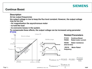
Continue Boost
Description
At low output frequencies
the output voltage is low to keep the flux level constant. However, the output voltage
may be too low
- for magnetisation the asynchronous motor
- to hold the load
- to overcome losses in the system.
To compensate these effects, the output voltage can be increased using parameter
P1310.
Related Parameters
P1310 Continue Boost
P0305 Rated motor current
P0350 Stator resistance
(line-to-line)
P0310 Motor Rated
frequency
14.
Page 14 SINAMICSV20 Technical Training I DT MC M3BF
Acceleration boost
Description
Acceleration boost will only produce boost during ramping, and is therefore useful for
additional torque during acceleration and deceleration
Related Parameters
P1311 Acceleration Boost
P0305 Rated motor current
P0350 Stator resistance (line-to-line)
boost
15.
Page 15 SINAMICSV20 Technical Training I DT MC M3BF
Starting boost
Description
Applies a constant linear offset (in [%] relative to P0305 (rated motor current)) to active V/f curve (either
linear or quadratic) after an ON command and is active until
1) ramp output reaches setpoint for the first time respectively
2) setpoint is reduced to less than present ramp output
Related Parameters
P1312 Starting Boost
P0305 Rated motor current
P0350 Stator resistance (line-to-line)
boost
16.
Page 16 SINAMICSV20 Technical Training I DT MC M3BF
PID – illustration
(Parallel PID set-up)
What do
I want?
What is
actual
value?
What is
the
deviation?
each PID terms
calculate
accordingly
PID has a
collective
"decision"
System
alters...
17.
Page 17 SINAMICSV20 Technical Training I DT MC M3BF
PID Setting
P
I
D
18.
Page 18 SINAMICSV20 Technical Training I DT MC M3BF
Braking Function
Dynamic Braking
Dynamic braking converts the regenerative energy, which is released
when the motor brakes, into heat. An internal chopper control (braking
chopper) in the inverter, which can control an external braking resistor, is
required for dynamic braking. The inverter controls the dynamic braking
depending on the DC link voltage.
Related parameters: P1237
Hold Braking
The motor holding brake prevents the motor from undesirable turning when the
inverter is switched-off. The inverter has internal logic to control a motor holding
brake.
Related parameters: P1215~P1217
DC Braking
DC braking causes the motor to stop rapidly by applying a DC braking current .
Related parameters: P1230~P1234
Compound Braking
For compound braking, DC braking is superimposed with regenerative braking
Effective braking is obtained without having to use additional components by
optimizing the ramp-down time and using compound braking.
Related parameter: P1236
Can not keep for
long time
19.
Page 19 SINAMICSV20 Technical Training I DT MC M3BF
Advance Function
20.
Page 20 SINAMICSV20 Technical Training I DT MC M3BF
Automatic Restart Function
After a power failure (F3 "Undervoltage"), the automatic restart function (enabled using P1210)
automatically powers up the inverter again. Any faults are automatically acknowledged by the
inverter.
When it comes to power failures (line supply failure), then a differentiation is made between the following
conditions:
● "Line undervoltage (mains brownout)" is a situation where the line supply is interrupted and returns
before (if installed) the BOP display has gone dark (this is an extremely short line supply interruption where
the DC link hasn't completely collapsed).
● "Line failure (mains blackout)" is a situation where the display has gone dark (this represents a longer
line supply interruption where the DC link has completely collapsed) before the line supply returns.
V20 output
frequency
Power Supply
t
t
t
ON command
Related
Parameter
s
21.
Page 21 SINAMICSV20 Technical Training I DT MC M3BF
Flying Start Function
The flying start function (enabled using P1200) allows the inverter to be switched onto a
motor which is still spinning by rapidly changing the output frequency of the inverter until the
actual motor speed has been found. Then, the motor runs up to setpoint using the normal
ramp time.
22.
Page 22 SINAMICSV20 Technical Training I DT MC M3BF
Super Torque
Apply a Torque Pulse when starting (Sticky Pumps)
time
time
Boost (%)
Output
Frequency (Hz)
P3355
P3354
P3356
Ramp-up time
P1120
Super torque Ramp time
P3353
23.
Page 23 SINAMICSV20 Technical Training I DT MC M3BF
Hammer Start
Apply lots of torque pulses when starting (very sticky Pumps)
time
time
Boost (%)
Output
Frequency (Hz)
P3357
P3354
Ramp-up time
P1120
No. of hammer cycles
P3358
P3359 P3360
Super torque Ramp time
P3353
24.
Page 24 SINAMICSV20 Technical Training I DT MC M3BF
Blockage Clear
Reverse motor to clear a blocked pump
25.
Page 25 SINAMICSV20 Technical Training I DT MC M3BF
Frost Protection
If the ambient temperature falls below a given threshold, motor
turns automatically to prevent freezing.
P3852 BI: Enable frost protection
In-house
10°C
Out-door
-10°C
26.
Page 26 SINAMICSV20 Technical Training I DT MC M3BF
Condensation Protection
If condensation sensor detects excessive condensation, inverter applies a DC current to keep
motor warm to prevent condensation
27.
Page 27 SINAMICSV20 Technical Training I DT MC M3BF
Pump Staging Function
Motor staging allows the control of up to 2 additional staged pumps or fans, based on a PID control
system.
The complete system consists of one pump controlled by the inverter with up to 2 further pumps /
fans controlled from contactors or motor starters which are controlled by outputs from the inverter
Related parameters: P2370: Motor staging stop mode
P2371:Motor staging configuration
28.
Page 28 SINAMICSV20 Technical Training I DT MC M3BF
Sleep Mode
Motor is turned off if demand falls below threshold, turns on if demand rises above threshold
Related parameters:
P2365: Hibernation enable / disable
P2366: Delay before stopping motor [s]
P2367: Delay before starting motor [s]
29.
Page 29 SINAMICSV20 Technical Training I DT MC M3BF
Parameter Cloning (1/2)
Customer can use Programming module to clone parameter with give power supply to V20
module
Programming Module
30.
Page 30 SINAMICSV20 Technical Training I DT MC M3BF
Parameter Cloning (2/2)
Transferring data from
inverter
to MMC / SD card
P0003=3
P0010=30
P0804 = 0 (default): file name is clone00.bin
P0804 = 1: file name is clone01.bin
...
P0804 = 99: file name is clone99.bin
P0802 (transfer data from inverter to card) = 2
Transferring data from MMC /
SD card to inverter
Power on the inverter from either the
mains supply or the built-in battery by pressing
the power button on the programming module.
Data transfer starts automatically and the
LED is lit up orange and flashes at 1 Hz. Then
the fault code F395 displays which means
"Cloning has occurred. Are you sure to keep the
clone edits?".
To save the clone edits, press OK button
and the fault code is cleared. To clear the fault
code
without saving the clone edits, remove the
programming module from the inverter.


![Page 15 SINAMICS V20 Technical Training I DT MC M3BF
Starting boost
Description
Applies a constant linear offset (in [%] relative to P0305 (rated motor current)) to active V/f curve (either
linear or quadratic) after an ON command and is active until
1) ramp output reaches setpoint for the first time respectively
2) setpoint is reduced to less than present ramp output
Related Parameters
P1312 Starting Boost
P0305 Rated motor current
P0350 Stator resistance (line-to-line)
boost](https://image.slidesharecdn.com/v20trainingslides-functionintroductionlyv8en-250819181557-e2234767/85/V20-training-slides-Function-introduction_LY_V8_EN-ppt-15-320.jpg)


![Page 28 SINAMICS V20 Technical Training I DT MC M3BF
Sleep Mode
Motor is turned off if demand falls below threshold, turns on if demand rises above threshold
Related parameters:
P2365: Hibernation enable / disable
P2366: Delay before stopping motor [s]
P2367: Delay before starting motor [s]](https://image.slidesharecdn.com/v20trainingslides-functionintroductionlyv8en-250819181557-e2234767/85/V20-training-slides-Function-introduction_LY_V8_EN-ppt-28-320.jpg)


