Download to read offline
![38
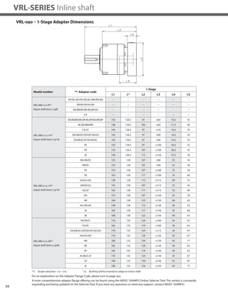
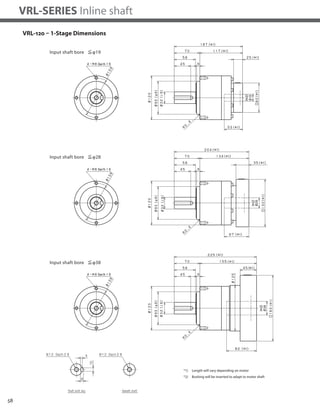
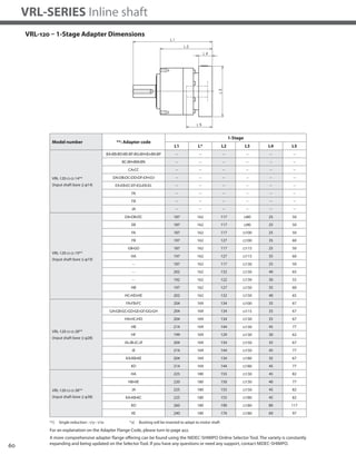
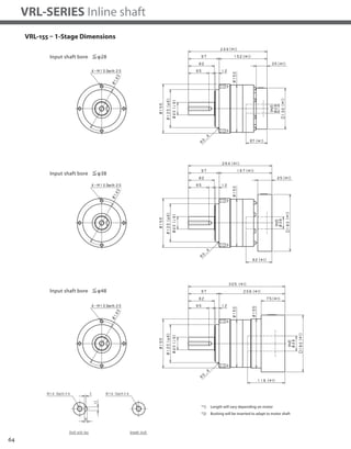
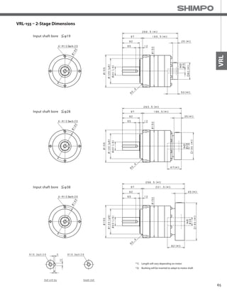
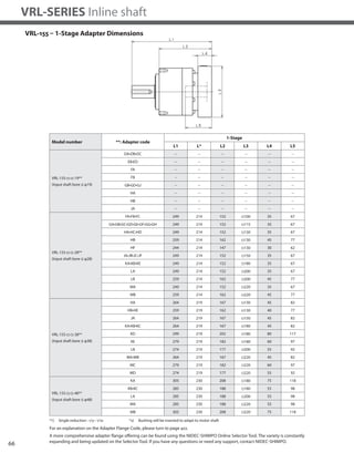
VRL-SERIES Inline shaft
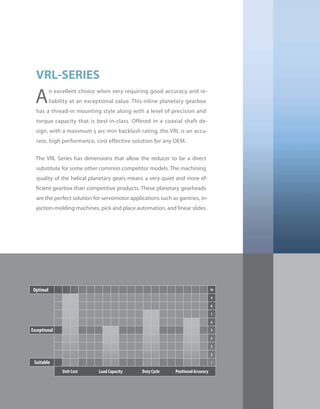
VRL-050 – 1-Stage Specifications
Frame Size 050
Stage 1-Stage
Ratio Units Note 3 4 5 6 7 8 9 10
Nominal Output Torque [Nm] *1 6 9 9 9 9 9 6 6
Maximum Acceleration Torque [Nm] *2 12 18 18 18 18 18 12 12
Emergency Stop Torque [Nm] *3 30 35 35 35 35 35 30 30
Nominal Input Speed [rpm] *4 4000
Maximum Input Speed [rpm] *5 8000
No Load Running Torque [Nm] *6 0.03
Permitted Radial Load [N] *7 240 270 290 310 320 340 350 360
Permitted Axial Load [N] *8 270 300 330 360 380 410 430 450
Maximum Radial Load [N] *9 710
Maximum Axial Load [N] *10 640
Moment of Inertia (≤Ø 8) [kgcm2] -- 0.053 0.041 0.036 0.034 0.032 0.031 0.031 0.030
Moment of Inertia (≤ Ø 14) [kgcm2] -- 0.091 0.079 0.074 0.072 0.071 0.070 0.069 0.069
Efficiency [%] *11 95
Torsional Rigidity [Nm/arc-min] *12 2
Maximum Torsional Backlash [arc-min] -- ≤ 5
Noise Level [dB] *13 61
Protection Class -- *14 IP54 (IP65)
Ambient Temperature [°C] -- 0-40
Permitted Housing Temperature [°C] -- 90
Weight [kg] *15 0.7
Frame Size 050
Stage 2-Stage
Ratio Units Note 15 16 20 25 28 30 35 40
Nominal Output Torque [Nm] *1 6 9 9 9 9 9 9 9
Maximum Acceleration Torque [Nm] *2 12 18 18 18 18 12 18 18
Emergency Stop Torque [Nm] *3 30 35 35 35 35 30 35 35
Nominal Input Speed [rpm] *4 4000
Maximum Input Speed [rpm] *5 8000
No Load Running Torque [Nm] *6 0.01
Permitted Radial Load [N] *7 410 420 460 490 510 520 550 570
Permitted Axial Load [N] *8 540 550 610 640 640 640 640 640
Maximum Radial Load [N] *9 710
Maximum Axial Load [N] *10 640
Moment of Inertia (≤Ø 8) [kgcm2] -- 0.035 0.038 0.034 0.034 0.038 0.030 0.034 0.030
Moment of Inertia (≤ Ø 14) [kgcm2] -- -- -- -- -- -- -- -- --
Efficiency [%] *11 90
Torsional Rigidity [Nm/arc-min] *12 2
Maximum Torsional Backlash [arc-min] -- ≤ 7
Noise Level [dB] *13 61
Protection Class -- *14 IP54 (IP65)
Ambient Temperature [°C] -- 0-40
Permitted Housing Temperature [°C] -- 90
Weight [kg] *15 0.8
VRL-050 – 2-Stage Specifications](https://image.slidesharecdn.com/shimpovrl-series-140807090526-phpapp01/85/Shimpo-vrl-series-7-320.jpg)
![39
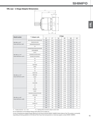
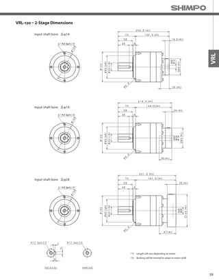
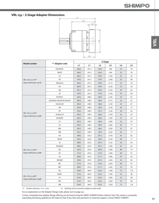
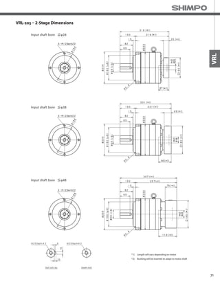
VRL
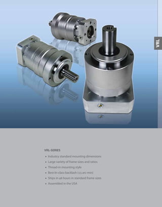
Frame Size 050
Stage 2-Stage
Ratio Units Note 45 50 60 70 80 90 100
Nominal Output Torque [Nm] *1 6 9 9 9 9 6 6
Maximum Acceleration Torque [Nm] *2 12 18 18 18 18 12 12
Emergency Stop Torque [Nm] *3 30 35 35 35 35 30 30
Nominal Input Speed [rpm] *4 4000
Maximum Input Speed [rpm] *5 8000
No Load Running Torque [Nm] *6 0.01
Permitted Radial Load [N] *7 600 620 660 690 710 710 710
Permitted Axial Load [N] *8 640 640 640 640 640 640 640
Maximum Radial Load [N] *9 710
Maximum Axial Load [N] *10 640
Moment of Inertia (≤Ø 8) [kgcm2] -- 0.034 0.030 0.030 0.030 0.030 0.030 0.030
Moment of Inertia (≤ Ø 14) [kgcm2] -- -- -- -- -- -- -- --
Efficiency [%] *11 90
Torsional Rigidity [Nm/arc-min] *12 2
Maximum Torsional Backlash [arc-min] -- ≤ 7
Noise Level [dB] *13 61
Protection Class -- *14 IP54 (IP65)
Ambient Temperature [°C] -- 0-40
Permitted Housing Temperature [°C] -- 90
Weight [kg] *15 0.8
*1) At nominal input speed, service life is 20,000 hours
*2) The maximum torque when starting or stopping operation
*3) The maximum torque allowed under a stress situation (Permitted 1,000 times during service life)
*4) The average input speed
*5) The maximum intermittent input speed
*6) This is the torque at no load applied on the input shaft. The input speed is 4,000 rpm for VRL 050
*7) At this load and nominal input speed, service life will be 20,000 hours. (The radial load applied to the output side bearing)
*8) At this load and nominal input speed, service life will be 20,000 hours. (The axial load applied to the output shaft center)
*9) The maximum radial load that the reducer can accept
*10) The maximum axial load that the reducer can accept
*11) The efficiency at the nominal torque rating
*12) This does not include the lost motion
*13) Contact NIDEC-SHIMPO for the testing conditions and environment
*14) IP65 (wash-down) is available as an option. Contact NIDEC-SHIMPO for more details and our food grade options
*15) The weight may vary slightly between models
VRL-050 – 2-Stage Specifications](https://image.slidesharecdn.com/shimpovrl-series-140807090526-phpapp01/85/Shimpo-vrl-series-8-320.jpg)
![44
VRL-SERIES Inline shaft
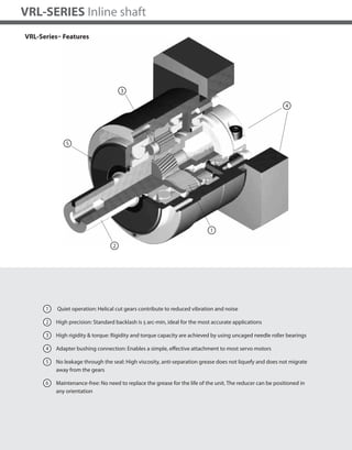
VRL-070 – 1-Stage Specifications
VRL-070 – 2-Stage Specifications
Frame Size 070
Stage 1-Stage
Ratio Unit Note 3 4 5 6 7 8 9 10
Nominal Output Torque [Nm] *1 18 27 27 27 27 27 18 18
Maximum Output Torque [Nm] *2 35 50 50 50 50 50 35 35
Emergency Stop Torque [Nm] *3 80 100 100 100 100 100 80 80
Nominal Input Speed [rpm] *4 3000
Maximum Input Speed [rpm] *5 6000
No Load Running Torque [Nm] *6 0.08
Permitted Radial Load [N] *7 430 470 510 540 570 600 620 640
Permitted Axial Load [N] *8 310 360 390 430 460 480 510 530
Maximum Radial Load [N] *9 1200
Maximum Axial Load [N] *10 1100
Moment of Inertia (≤Ø 8) [kgcm2] -- 0.140 0.095 0.077 0.068 0.062 0.059 0.057 0.056
Moment of Inertia (≤ Ø 14) [kgcm2] -- 0.220 0.170 0.160 0.150 0.140 0.140 0.140 0.140
Moment of Inertia (≤ Ø 19) [kgcm2] -- 0.430 0.380 0.360 0.360 0.350 0.350 0.340 0.340
Efficiency [%] *11 95
Torsional Rigidity [Nm/arcmin] *12 3
Maximum Torsional Backlash [Arc-min] -- ≤ 5
Noise Level [dB] *13 ≤ 66
Protection Class -- *14 IP54 (IP65)
Ambient Temperature [°C] -- 0-40
Permitted Housing Temperature [°C] -- 90
Weight [kg] *15 1.5
Frame Size 070
Stage 2-Stage
Ratio Unit Note 15 16 20 25 28 30 35 40
Nominal Output Torque [Nm] *1 18 27 27 27 27 18 27 27
Maximum Output Torque [Nm] *2 35 50 50 50 50 35 50 50
Emergency Stop Torque [Nm] *3 80 100 100 100 100 80 100 100
Nominal Input Speed [rpm] *4 3000
Maximum Input Speed [rpm] *5 6000
No Load Running Torque [Nm] *6 0.04
Permitted Radial Load [N] *7 740 750 810 870 910 930 980 1000
Permitted Axial Load [N] *8 630 650 720 790 830 860 920 970
Maximum Radial Load [N] *9 1200
Maximum Axial Load [N] *10 1100
Moment of Inertia (≤Ø 8) [kgcm2] -- 0.055 0.057 0.054 0.053 0.055 0.049 0.053 0.049
Moment of Inertia (≤ Ø 14) [kgcm2] -- 0.140 0.140 0.130 0.130 0.140 0.130 0.130 0.130
Moment of Inertia (≤ Ø 19) [kgcm2] -- 0.350 0.360 0.350 0.350 0.360 0.340 0.350 0.340
Efficiency [%] *11 90
Torsional Rigidity [Nm/arcmin] *12 3
Maximum Torsional Backlash [Arc-min] -- ≤ 5
Noise Level [dB] *13 ≤ 66
Protection Class -- *14 IP54 (IP65)
Ambient Temperature [°C] -- 0-40
Permitted Housing Temperature [°C] -- 90
Weight [kg] *15 1.7](https://image.slidesharecdn.com/shimpovrl-series-140807090526-phpapp01/85/Shimpo-vrl-series-13-320.jpg)
![45
VRL
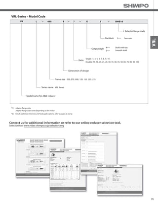
*1) At nominal input speed, service life is 20,000 hours
*2) The maximum torque when starting or stopping operation
*3) The maximum torque allowed under a stress situation (Permitted 1,000 times during service life)
*4) The average input speed
*5) The maximum intermittent input speed
*6) This is the torque at no load applied on the input shaft. The input speed is 3,000 rpm for VRL 070
*7) At this load and nominal input speed, service life will be 20,000 hours. (The radial load applied to the output side bearing)
*8) At this load and nominal input speed, service life will be 20,000 hours. (The axial load applied to the output shaft center)
*9) The maximum radial load that the reducer can accept
*10) The maximum axial load that the reducer can accept
*11) The efficiency at the nominal torque rating
*12) This does not include the lost motion
*13) Contact NIDEC-SHIMPO for the testing conditions and environment
*14) IP65 (wash-down) is available as an option. Contact NIDEC-SHIMPO for more details and our food grade options
*15) The weight may vary slightly between models
VRL-070 – 2-Stage Specifications
Frame Size 070
Stage 2-Stage
Ratio Unit Note 45 50 60 70 80 90 100
Nominal Output Torque [Nm] *1 18 27 27 27 27 18 18
Maximum Output Torque [Nm] *2 35 50 50 50 50 35 35
Emergency Stop Torque [Nm] *3 80 100 100 100 100 80 80
Nominal Input Speed [rpm] *4 3000
Maximum Input Speed [rpm] *5 6000
No Load Running Torque [Nm] *6 0.04
Permitted Radial Load [N] *7 1100 1100 1200 1200 1200 1200 1200
Permitted Axial Load [N] *8 1000 1100 1100 1100 1100 1100 1100
Maximum Radial Load [N] *9 1200
Maximum Axial Load [N] *10 1100
Moment of Inertia (≤Ø 8) [kgcm2] -- 0.053 0.049 0.049 0.049 0.049 0.049 0.049
Moment of Inertia (≤ Ø 14) [kgcm2] -- 0.130 0.130 0.130 0.130 0.130 0.13 0.13
Moment of Inertia (≤ Ø 19) [kgcm2] -- 0.350 0.340 0.340 0.340 0.340 0.340 0.340
Efficiency [%] *11 90
Torsional Rigidity [Nm/arcmin] *12 3
Maximum Torsional Backlash [Arc-min] -- ≤ 5
Noise Level [dB] *13 ≤ 66
Protection Class -- *14 IP54 (IP65)
Ambient Temperature [°C] -- 0-40
Permitted Housing Temperature [°C] -- 90
Weight [kg] *15 1.7](https://image.slidesharecdn.com/shimpovrl-series-140807090526-phpapp01/85/Shimpo-vrl-series-14-320.jpg)
![50
VRL-SERIES Inline shaft
Frame Size 090
Stage 1-Stage
Ratio Unit Note 3 4 5 6 7 8 9 10
Nominal Output Torque [Nm] *1 50 75 75 75 75 75 50 50
Maximum Acceleration Torque [Nm] *2 80 125 125 125 125 125 80 80
Emergency Stop Torque [Nm] *3 200 250 250 250 250 250 200 200
Nominal Input Speed [rpm] *4 3000
Maximum Input Speed [rpm] *5 6000
No Load Running Torque [Nm] *6 0.35
Permitted Radial Load [N] *7 810 890 960 1000 1100 1100 1200 1200
Permitted Axial Load [N] *8 930 1100 1200 1300 1300 1400 1500 1600
Maximum Radial Load [N] *9 2400
Maximum Axial Load [N] *10 2200
Moment of Inertia (≤Ø 8) [kgcm2] -- -- -- -- -- -- -- -- --
Moment of Inertia (≤ Ø 14) [kgcm2] -- 0.720 0.490 0.400 0.360 0.320 0.310 0.290 0.290
Moment of Inertia (≤ Ø 19) -- -- 1.200 0.950 0.860 0.820 0.790 0.770 0.760 0.750
Moment of Inertia (≤ Ø 28) [kgcm2] -- 3.200 3.000 2.900 2.800 2.800 2.800 2.800 2.800
Efficiency [%] *11 95
Torsional Rigidity [Nm/arc-min] *12 10
Maximum Torsional Backlash [arc-min] -- ≤ 5
Noise Level [dB] *13 67
Protection Class -- *14 IP54 (IP65)
Ambient Temperature [°C] -- 0-40
Permitted Housing Temperature [°C] -- 90
Weight [kg] *15 3.5
Frame Size 090
Stage 2-Stage
Ratio Unit Note 15 16 20 25 28 30 35 40
Nominal Output Torque [Nm] *1 50 75 75 75 75 50 75 75
Maximum Acceleration Torque [Nm] *2 80 125 125 125 125 80 125 125
Emergency Stop Torque [Nm] *3 200 250 250 250 250 200 250 250
Nominal Input Speed [rpm] *4 3000
Maximum Input Speed [rpm] *5 6000
No Load Running Torque [Nm] *6 0.06
Permitted Radial Load [N] *7 1400 1400 1500 1600 1700 1700 1800 1900
Permitted Axial Load [N] *8 1900 1900 2100 2200 2200 2200 2200 2200
Maximum Radial Load [N] *9 2400
Maximum Axial Load [N] *10 2200
Moment of Inertia (≤Ø 8) [kgcm2] -- 0.130 0.150 0.130 0.120 0.140 0.100 0.120 0.099
Moment of Inertia (≤ Ø 14) [kgcm2] -- 0.280 0.300 0.280 0.280 0.290 0.250 0.270 0.250
Moment of Inertia (≤ Ø 19) -- -- 0.720 0.740 0.720 0.710 0.730 0.700 0.710 0.700
Moment of Inertia (≤ Ø 28) [kgcm2] -- 2.700 2.800 2.700 2.700 2.700 2.600 2.700 2.600
Efficiency [%] *11 90
Torsional Rigidity [Nm/arc-min] *12 10
Maximum Torsional Backlash [arc-min] -- ≤ 5
Noise Level [dB] *13 67
Protection Class -- *14 IP54 (IP65)
Ambient Temperature [°C] -- 0-40
Permitted Housing Temperature [°C] -- 90
Weight [kg] *15 4
VRL-090 – 1-Stage Specifications
VRL-090 – 2-Stage Specifications](https://image.slidesharecdn.com/shimpovrl-series-140807090526-phpapp01/85/Shimpo-vrl-series-19-320.jpg)
![51
VRL
Frame Size 090
Stage 2-Stage
Ratio Unit Note 45 50 60 70 80 90 100
Nominal Output Torque [Nm] *1 50 75 75 75 75 50 50
Maximum Acceleration Torque [Nm] *2 80 125 125 125 125 80 80
Emergency Stop Torque [Nm] *3 200 250 250 250 250 200 200
Nominal Input Speed [rpm] *4 3000
Maximum Input Speed [rpm] *5 6000
No Load Running Torque [Nm] *6 0.06
Permitted Radial Load [N] *7 2000 2100 2200 2300 2400 2400 2400
Permitted Axial Load [N] *8 2200 2200 2200 2200 2200 2200 2200
Maximum Radial Load [N] *9 2400
Maximum Axial Load [N] *10 2200
Moment of Inertia (≤Ø 8) [kgcm2] -- 0.120 0.098 0.098 0.097 0.097 0.097 0.097
Moment of Inertia (≤ Ø 14) [kgcm2] -- 0.270 0.250 0.250 0.250 0.250 0.250 0.250
Moment of Inertia (≤ Ø 19) -- -- 0.710 0.690 0.690 0.690 0.690 0.690 0.690
Moment of Inertia (≤ Ø 28) [kgcm2] -- 2.700 2.600 2.600 2.600 2.600 2.600 2.600
Efficiency [%] *11 90
Torsional Rigidity [Nm/arc-min] *12 10
Maximum Torsional Backlash [arc-min] -- ≤ 5
Noise Level [dB] *13 67
Protection Class -- *14 IP54 (IP65)
Ambient Temperature [°C] -- 0-40
Permitted Housing Temperature [°C] -- 90
Weight [kg] *15 4
VRL-090 – 2-Stage Specifications
*1) At nominal input speed, service life is 20,000 hours
*2) The maximum torque when starting or stopping operation
*3) The maximum torque allowed under a stress situation (Permitted 1,000 times during service life)
*4) The average input speed
*5) The maximum intermittent input speed
*6) This is the torque at no load applied on the input shaft. The input speed is 3,000 rpm for VRL 090
*7) At this load and nominal input speed, service life will be 20,000 hours. (The radial load applied to the output side bearing)
*8) At this load and nominal input speed, service life will be 20,000 hours. (The axial load applied to the output shaft center)
*9) The maximum radial load that the reducer can accept
*10) The maximum axial load that the reducer can accept
*11) The efficiency at the nominal torque rating
*12) This does not include the lost motion
*13) Contact NIDEC-SHIMPO for the testing conditions and environment
*14) IP65 (wash-down) is available as an option. Contact NIDEC-SHIMPO for more details and our food grade options
*15) The weight may vary slightly between models](https://image.slidesharecdn.com/shimpovrl-series-140807090526-phpapp01/85/Shimpo-vrl-series-20-320.jpg)
![56
VRL-SERIES Inline shaft
VRL-120 – 1-Stage Specifications
Frame Size 120
Stage 1-Stage
Ratio Unit Note 3 4 5 6 7 8 9 10
Nominal Output Torque [Nm] *1 120 120 180 180 180 180 120 120
Maximum Output Torque [Nm] *2 225 330 330 330 330 330 225 225
Emergency Stop Torque [Nm] *3 500 625 625 625 625 625 500 500
Nominal Input Speed [rpm] *4 3000
Maximum Input Speed [rpm] *5 6000
No Load Running Torque [Nm] *14 1.30
Permitted Radial Load [N] *6 1300 1500 1600 1700 1800 1900 1900 2000
Permitted Axial Load [N] *7 1500 1700 1900 2000 2100 2300 2400 2500
Maximum Radial Load [N] *8 4300
Maximum Axial Load [N] *9 3900
Moment of Inertia (≤Ø 14) [kgcm2] -- -- -- -- -- -- -- --
Moment of Inertia (≤ Ø 19) [kgcm2] 3.300 2.000 1.600 1.300 1.100 1.000 0.980 0.950
Moment of Inertia (≤ Ø 28) [kgcm2] 5.300 4.100 3.600 3.300 3.200 3.100 3.000 3.000
Moment of Inertia (≤ Ø 38) [kgcm2] 13.000 12.000 11.000 11.000 11.000 11.000 11.000 11.000
Efficiency [%] *11 95
Torsional Rigidity [Nm/arc-min] *12 31
Maximum Torsional Backlash [arc-min] -- ≤ 5
Noise Level [dB] *13 71
Protection Class *15 IP54 (IP65)
Ambient Temperature [°C] 0-40
Permitted Housing Temperature [°C] *16 90
Weight [kg] *10 7.8
VRL-120 – 2-Stage Specifications
Frame Size 120
Stage 2-Stage
Ratio Unit Note 15 16 20 25 28 30 35 40
Nominal Output Torque [Nm] *1 120 180 180 180 180 120 180 180
Maximum Output Torque [Nm] *2 225 330 330 330 330 225 330 330
Emergency Stop Torque [Nm] *3 500 625 625 625 625 500 625 625
Nominal Input Speed [rpm] *4 3000
Maximum Input Speed [rpm] *5 6000
No Load Running Torque [Nm] *14 0.42
Permitted Radial Load [N] *6 2300 2300 2500 2700 2800 2900 3000 3200
Permitted Axial Load [N] *7 3000 3100 3400 3700 3900 3900 3900 3900
Maximum Radial Load [N] *8 4300
Maximum Axial Load [N] *9 3900
Moment of Inertia (≤Ø 14) [kgcm2] 0.430 0.480 0.400 0.380 0.440 0.290 0.370 0.280
Moment of Inertia (≤ Ø 19) [kgcm2] 0.860 0.920 0.830 0.820 0.880 0.740 0.810 0.730
Moment of Inertia (≤ Ø 28) [kgcm2] 2.800 2.900 2.800 2.800 2.800 2.700 2.700 2.700
Moment of Inertia (≤ Ø 38) [kgcm2] -- -- -- -- -- -- -- --
Efficiency [%] *11 90
Torsional Rigidity [Nm/arc-min] *12 31
Maximum Torsional Backlash [arc-min] -- ≤ 5
Noise Level [dB] *13 71
Protection Class *15 IP54 (IP65)
Ambient Temperature [°C] 0-40
Permitted Housing Temperature [°C] *16 90
Weight [kg] *10 8.7](https://image.slidesharecdn.com/shimpovrl-series-140807090526-phpapp01/85/Shimpo-vrl-series-25-320.jpg)
![57
VRL
VRL-120 – 2-Stage Specifications
Frame Size 120
Stage 2-Stage
Ratio Unit Note 45 50 60 70 80 90 100
Nominal Output Torque [Nm] *1 120 180 180 180 180 120 120
Maximum Output Torque [Nm] *2 225 330 330 330 330 225 225
Emergency Stop Torque [Nm] *3 500 625 625 625 625 500 500
Nominal Input Speed [rpm] *4 3000
Maximum Input Speed [rpm] *5 6000
No Load Running Torque [Nm] *14 0.42
Permitted Radial Load [N] *6 3300 3400 3600 3800 4000 4200 4300
Permitted Axial Load [N] *7 3900 3900 3900 3900 3900 3900 3900
Maximum Radial Load [N] *8 4300
Maximum Axial Load [N] *9 3900
Moment of Inertia (≤Ø 14) [kgcm2] 0.370 0.280 0.280 0.280 0.280 0.270 0.270
Moment of Inertia (≤ Ø 19) [kgcm2] 0.800 0.730 0.730 0.730 0.730 0.730 0.730
Moment of Inertia (≤ Ø 28) [kgcm2] 2.700 2.700 2.700 2.700 2.700 2.700 2.700
Moment of Inertia (≤ Ø 38) [kgcm2] -- -- -- -- -- -- --
Efficiency [%] *11 90
Torsional Rigidity [Nm/arc-min] *12 31
Maximum Torsional Backlash [arc-min] -- ≤ 5
Noise Level [dB] *13 71
Protection Class *15 IP54 (IP65)
Ambient Temperature [°C] 0-40
Permitted Housing Temperature [°C] *16 90
Weight [kg] *10 8.7
*1) At nominal input speed, service life is 20,000 hours
*2) The maximum torque when starting or stopping operation
*3) The maximum torque allowed under a stress situation (Permitted 1,000 times during service life)
*4) The average input speed
*5) The maximum intermittent input speed
*6) This is the torque at no load applied on the input shaft. The input speed is 3,000 rpm for VRL 120
*7) At this load and nominal input speed, service life will be 20,000 hours. (The radial load applied to the output side bearing)
*8) At this load and nominal input speed, service life will be 20,000 hours. (The axial load applied to the output shaft center)
*9) The maximum radial load that the reducer can accept
*10) The maximum axial load that the reducer can accept
*11) The efficiency at the nominal torque rating
*12) This does not include the lost motion
*13) Contact NIDEC-SHIMPO for the testing conditions and environment
*14) IP65 (wash-down) is available as an option. Contact NIDEC-SHIMPO for more details and our food grade options
*15) The weight may vary slightly between models](https://image.slidesharecdn.com/shimpovrl-series-140807090526-phpapp01/85/Shimpo-vrl-series-26-320.jpg)
![62
VRL-SERIES Inline shaft
VRL-155 – 1-Stage Specifications
VRL-155 – 2-Stage Specifications
Frame Size 155
Stage 1-Stage
Ratio Unit Note 3 4 5 6 7 8 9 10
Nominal Output Torque [Nm] *1 240 240 360 360 360 360 240 240
Maximum Acceleration Torque [Nm] *2 470 700 700 700 700 700 470 470
Emergency Stop Torque [Nm] *3 1000 1250 1250 1250 1250 1250 1000 1000
Nominal Input Speed [rpm] *4 2000
Maximum Input Speed [rpm] *5 4000
No Load Running Torque [Nm] *6 1.63
Permitted Radial Load [N] *7 3200 3500 3800 4000 4200 4400 4600 4700
Permitted Axial Load [N] *8 2400 2700 3000 3300 3500 3700 3900 4100
Maximum Radial Load [N] *9 9100
Maximum Axial Load [N] *10 8200
Moment of Inertia (≤Ø 19) [kgcm2] -- -- -- -- -- -- -- -- --
Moment of Inertia (≤ Ø 28) [kgcm2] -- 12.000 7.500 5.800 4.900 4.100 3.800 3.600 3.500
Moment of Inertia (≤ Ø 38) [kgcm2] -- 20.000 15.000 14.000 13.000 12.000 12.000 11.000 11.000
Moment of Inertia (≤ Ø 48) [kgcm2] -- 42.000 37.000 36.000 35.000 34.000 34.000 34.000 34.000
Efficiency [%] *11 95
Torsional Rigidity [Nm/arc-min] *12 60
Maximum Torsional Backlash [arc-min] -- ≤ 5
Noise Level [dB] *13 67
Protection Class -- *14 IP54 (IP65)
Ambient Temperature [°C] -- 0-40
Permitted Housing Temperature [°C] -- 90
Weight [kg] *15 16
Frame Size 155
Stage 2-Stage
Ratio Unit Note 15 16 20 25 28 30 35 40
Nominal Output Torque [Nm] *1 240 360 360 360 360 240 360 360
Maximum Acceleration Torque [Nm] *2 470 700 700 700 700 470 700 700
Emergency Stop Torque [Nm] *3 1000 1250 1250 1250 1250 1000 1250 1250
Nominal Input Speed [rpm] *4 2000
Maximum Input Speed [rpm] *5 4000
No Load Running Torque [Nm] *6 0.56
Permitted Radial Load [N] *7 5400 5500 6000 6400 6700 6800 7200 7500
Permitted Axial Load [N] *8 4900 5000 5500 6100 6400 6600 7000 7500
Maximum Radial Load [N] *9 9100
Maximum Axial Load [N] *10 8200
Moment of Inertia (≤Ø 19) [kgcm2] -- 1.300 1.500 1.200 1.100 1.400 0.850 1.100 0.830
Moment of Inertia (≤ Ø 28) [kgcm2] -- 3.200 3.500 3.100 3.100 3.300 2.800 3.100 2.800
Moment of Inertia (≤ Ø 38) [kgcm2] -- 11.000 11.000 11.000 11.000 11.000 10.000 11.000 10.000
Moment of Inertia (≤ Ø 48) [kgcm2] -- -- -- -- -- -- -- -- --
Efficiency [%] *11 90
Torsional Rigidity [Nm/arc-min] *12 60
Maximum Torsional Backlash [arc-min] -- ≤ 5
Noise Level [dB] *13 67
Protection Class -- *14 IP54 (IP65)
Ambient Temperature [°C] -- 0-40
Permitted Housing Temperature [°C] -- 90
Weight [kg] *15 18](https://image.slidesharecdn.com/shimpovrl-series-140807090526-phpapp01/85/Shimpo-vrl-series-31-320.jpg)
![63
VRL
VRL-155 – 2-Stage Specifications
Frame Size 155
Stage 2-Stage
Ratio Unit Note 45 50 60 70 80 90 100
Nominal Output Torque [Nm] *1 240 360 360 360 360 240 240
Maximum Acceleration Torque [Nm] *2 470 700 700 700 700 470 470
Emergency Stop Torque [Nm] *3 1000 1250 1250 1250 1250 1000 1000
Nominal Input Speed [rpm] *4 2000
Maximum Input Speed [rpm] *5 4000
No Load Running Torque [Nm] *6 0.56
Permitted Radial Load [N] *7 7800 8100 8600 9100 9100 9100 9100
Permitted Axial Load [N] *8 7900 8200 8200 8200 8200 8200 8200
Maximum Radial Load [N] *9 9100
Maximum Axial Load [N] *10 8200
Moment of Inertia (≤Ø 19) [kgcm2] -- 1.100 0.810 0.810 0.800 0.800 0.800 0.800
Moment of Inertia (≤ Ø 28) [kgcm2] -- 3.000 2.800 2.800 2.800 2.800 2.800 2.800
Moment of Inertia (≤ Ø 38) [kgcm2] -- 11.000 10.000 10.000 10.000 10.000 10.000 10.000
Moment of Inertia (≤ Ø 48) [kgcm2] -- -- -- -- -- -- -- --
Efficiency [%] *11 90
Torsional Rigidity [Nm/arc-min] *12 60
Maximum Torsional Backlash [arc-min] -- ≤ 5
Noise Level [dB] *13 67
Protection Class -- *14 IP54 (IP65)
Ambient Temperature [°C] -- 0-40
Permitted Housing Temperature [°C] -- 90
Weight [kg] *15 18
*1) At nominal input speed, service life is 20,000 hours
*2) The maximum torque when starting or stopping operation
*3) The maximum torque allowed under a stress situation (Permitted 1,000 times during service life)
*4) The average input speed
*5) The maximum intermittent input speed
*6) This is the torque at no load applied on the input shaft. The input speed is 2,000 rpm for VRL155
*7) At this load and nominal input speed, service life will be 20,000 hours. (The radial load applied to the output side bearing)
*8) At this load and nominal input speed, service life will be 20,000 hours. (The axial load applied to the output shaft center)
*9) The maximum radial load that the reducer can accept
*10) The maximum axial load that the reducer can accept
*11) The efficiency at the nominal torque rating
*12) This does not include the lost motion
*13) Contact NIDEC-SHIMPO for the testing conditions and environment
*14) IP65 (wash-down) is available as an option. Contact NIDEC-SHIMPO for more details and our food grade options
*15) The weight may vary slightly between models](https://image.slidesharecdn.com/shimpovrl-series-140807090526-phpapp01/85/Shimpo-vrl-series-32-320.jpg)
![68
VRL-SERIES Inline shaft
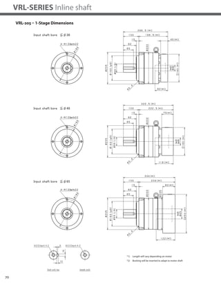
VRL-205 – 1-Stage Specifications
VRL-205 – 2-Stage Specifications
Frame Size 205
Stage 1-Stage
Ratio Unit Note 3 4 5 6 7 8 9 10
Nominal Output Torque [Nm] *1 500 750 750 750 750 750 500 500
Maximum Acceleration Torque [Nm] *2 970 1400 1400 1400 1400 1400 970 970
Emergency Stop Torque [Nm] *3 2200 2750 2750 2750 2750 2750 2200 2200
Nominal Input Speed [rpm] *4 1500
Maximum Input Speed [rpm] *5 3000
No Load Running Torque [Nm] *6 2.68
Permitted Radial Load [N] *7 5600 6200 6700 7100 7400 7800 8100 8400
Permitted Axial Load [N] *8 4300 4900 5400 5800 6300 6600 7000 7300
Maximum Radial Load [N] *9 15000
Maximum Axial Load [N] *10 14000
Moment of Inertia (≤Ø 28) [kgcm2] -- -- -- -- -- -- -- -- --
Moment of Inertia (≤ Ø 38) [kgcm2] -- 44.000 28.000 22.000 18.000 16.000 15.000 14.000 14.000
Moment of Inertia (≤ Ø 48) [kgcm2] -- 66.000 50.000 44.000 41.000 38.000 37.000 36.000 36.000
Moment of Inertia (≤ Ø 65) [kgcm2] -- 130.000 110.000 100.000 100.000 99.000 97.000 97.000 96.000
Efficiency [%] *11 95
Torsional Rigidity [Nm/arc-min] *12 175
Maximum Torsional Backlash [arc-min] -- ≤ 5
Noise Level [dB] *13 67
Protection Class -- *14 IP54 (IP65)
Ambient Temperature [°C] -- 0-40
Permitted Housing Temperature [°C] -- 90
Weight [kg] *15 39
Frame Size 205
Stage 2-Stage
Ratio Unit Note 15 16 20 25 28 30 35 40
Nominal Output Torque [Nm] *1 500 750 750 750 750 500 750 750
Maximum Acceleration Torque [Nm] *2 970 1400 1400 1400 1400 970 1400 1400
Emergency Stop Torque [Nm] *3 2200 2750 2750 2750 2750 2200 2750 2750
Nominal Input Speed [rpm] *4 1500
Maximum Input Speed [rpm] *5 3000
No Load Running Torque [Nm] *6 1.39
Permitted Radial Load [N] *7 9600 9800 11000 11000 12000 12000 13000 13000
Permitted Axial Load [N] *8 8700 8900 9900 11000 11000 12000 13000 13000
Maximum Radial Load [N] *9 15000
Maximum Axial Load [N] *10 14000
Moment of Inertia (≤Ø 28) [kgcm2] -- 4.700 5.400 4.400 4.200 4.900 3.200 4.100 3.200
Moment of Inertia (≤ Ø 38) [kgcm2] -- 12.000 13.000 12.000 12.000 13.000 11.000 12.000 11.000
Moment of Inertia (≤ Ø 48) [kgcm2] -- 34.000 35.000 34.000 34.000 35.000 33.000 34.000 33.000
Moment of Inertia (≤ Ø 65) [kgcm2] -- -- -- -- -- -- -- -- --
Efficiency [%] *11 90
Torsional Rigidity [Nm/arc-min] *12 175
Maximum Torsional Backlash [arc-min] -- ≤ 5
Noise Level [dB] *13 67
Protection Class -- *14 IP54 (IP65)
Ambient Temperature [°C] -- 0-40
Permitted Housing Temperature [°C] -- 90
Weight [kg] *15 40](https://image.slidesharecdn.com/shimpovrl-series-140807090526-phpapp01/85/Shimpo-vrl-series-37-320.jpg)
![69
VRL
VRL-205 – 2-Stage Specifications
Frame Size 205
Stage 2-Stage
Ratio Unit Note 45 50 60 70 80 90 100
Nominal Output Torque [Nm] *1 500 750 750 750 750 500 500
Maximum Acceleration Torque [Nm] *2 970 1400 1400 1400 1400 970 970
Emergency Stop Torque [Nm] *3 2200 2750 2750 2750 2750 2200 2200
Nominal Input Speed [rpm] *4 1500
Maximum Input Speed [rpm] *5 3000
No Load Running Torque [Nm] *6 1.39
Permitted Radial Load [N] *7 14000 14000 15000 15000 15000 15000 15000
Permitted Axial Load [N] *8 14000 14000 14000 14000 14000 14000 14000
Maximum Radial Load [N] *9 15000
Maximum Axial Load [N] *10 14000
Moment of Inertia (≤Ø 28) [kgcm2] -- 4.000 3.100 3.100 3.100 3.100 3.100 3.100
Moment of Inertia (≤ Ø 38) [kgcm2] -- 12.000 11.000 11.000 11.000 11.000 11.000 11.000
Moment of Inertia (≤ Ø 48) [kgcm2] -- 34.000 33.000 33.000 33.000 33.000 33.000 33.000
Moment of Inertia (≤ Ø 65) [kgcm2] -- -- -- -- -- -- -- --
Efficiency [%] *11 90
Torsional Rigidity [Nm/arc-min] *12 175
Maximum Torsional Backlash [arc-min] -- ≤ 5
Noise Level [dB] *13 67
Protection Class -- *14 IP54 (IP65)
Ambient Temperature [°C] -- 0-40
Permitted Housing Temperature [°C] -- 90
Weight [kg] *15 40
*1) At nominal input speed, service life is 20,000 hours
*2) The maximum torque when starting or stopping operation
*3) The maximum torque allowed under a stress situation (Permitted 1,000 times during service life)
*4) The average input speed
*5) The maximum intermittent input speed
*6) This is the torque at no load applied on the input shaft. The input speed is 1,500 rpm for VRL205
*7) At this load and nominal input speed, service life will be 20,000 hours. (The radial load applied to the output side bearing)
*8) At this load and nominal input speed, service life will be 20,000 hours. (The axial load applied to the output shaft center)
*9) The maximum radial load that the reducer can accept
*10) The maximum axial load that the reducer can accept
*11) The efficiency at the nominal torque rating
*12) This does not include the lost motion
*13) Contact NIDEC-SHIMPO for the testing conditions and environment
*14) IP65 (wash-down) is available as an option. Contact NIDEC-SHIMPO for more details and our food grade options
*15) The weight may vary slightly between models](https://image.slidesharecdn.com/shimpovrl-series-140807090526-phpapp01/85/Shimpo-vrl-series-38-320.jpg)
![74
VRL-SERIES Inline shaft
VRL-235 – 1-Stage Specifications
VRL-235 – 2-Stage Specifications
Frame Size 235
Stage 1-Stage
Ratio Unit Note 3 4 5 6 7 8 9 10
Nominal Output Torque [Nm] *1 1000 1500 1500 1500 1500 1500 1000 1000
Maximum Acceleration Torque [Nm] *2 1600 2300 2300 2300 2300 2200 1900 1600
Emergency Stop Torque [Nm] *3 4000 5000 5000 5000 5000 5000 4000 4000
Nominal Input Speed [rpm] *4 1000
Maximum Input Speed [rpm] *5 2000
No Load Running Torque [Nm] *6 2.92
Permitted Radial Load [N] *7 5800 6400 6900 7300 7700 8000 8400 8700
Permitted Axial Load [N] *8 6400 7200 7900 8600 9200 9700 10000 11000
Maximum Radial Load [N] *9 15000
Maximum Axial Load [N] *10 14000
Moment of Inertia (≤ Ø 38) [kgcm2] -- -- -- -- -- -- -- -- --
Moment of Inertia (≤ Ø 48) [kgcm2] -- 90.000 62.000 52.000 47.000 42.000 40.000 39.000 38.000
Moment of Inertia (≤ Ø 65) [kgcm2] -- 150.000 120.000 110.000 110.000 100.000 100.000 99.000 98.000
Efficiency [%] *11 97
Torsional Rigidity [Nm/arc-min] *12 400
Maximum Torsional Backlash [arc-min] -- ≤ 5
Noise Level [dB] *13 61
Protection Class -- *14 IP54 (IP65)
Ambient Temperature [°C] -- 0-40
Permitted Housing Temperature [°C] -- 90
Weight [kg] *15 55
Frame Size 235
Stage 2-Stage
Ratio Unit Note 15 16 20 25 28 30 35 40
Nominal Output Torque [Nm] *1 1000 1500 1500 1500 1500 1000 1500 1500
Maximum Acceleration Torque [Nm] *2 1600 2300 2300 2300 2300 1600 2300 2300
Emergency Stop Torque [Nm] *3 4000 5000 5000 5000 5000 4000 5000 5000
Nominal Input Speed [rpm] *4 1000
Maximum Input Speed [rpm] *5 2000
No Load Running Torque [Nm] *6 1.14
Permitted Radial Load [N] *7 9900 10000 11000 12000 12000 13000 13000 14000
Permitted Axial Load [N] *8 13000 13000 14000 14000 14000 14000 14000 14000
Maximum Radial Load [N] *9 15000
Maximum Axial Load [N] *10 14000
Moment of Inertia (≤ Ø 38) [kgcm2] -- 14.000 16.000 14.000 14.000 15.000 12.000 13.000 12.000
Moment of Inertia (≤ Ø 48) [kgcm2] -- 36.000 37.000 35.000 35.000 36.000 34.000 35.000 33.000
Moment of Inertia (≤ Ø 65) [kgcm2] -- -- -- -- -- -- -- -- --
Efficiency [%] *11 92
Torsional Rigidity [Nm/arc-min] *12 400
Maximum Torsional Backlash [arc-min] -- ≤ 5
Noise Level [dB] *13 61
Protection Class -- *14 IP54 (IP65)
Ambient Temperature [°C] -- 0-40
Permitted Housing Temperature [°C] -- 90
Weight [kg] *15 57](https://image.slidesharecdn.com/shimpovrl-series-140807090526-phpapp01/85/Shimpo-vrl-series-43-320.jpg)
![75
VRL
VRL-235 – 2-Stage Specifications
Frame Size 235
Stage 2-Stage
Ratio Unit Note 45 50 60 70 80 90 100
Nominal Output Torque [Nm] *1 1000 1500 1500 1500 1500 1000 1000
Maximum Acceleration Torque [Nm] *2 1300 2300 2300 2300 1800 1300 1200
Emergency Stop Torque [Nm] *3 4000 5000 5000 5000 5000 4000 4000
Nominal Input Speed [rpm] *4 1000
Maximum Input Speed [rpm] *5 2000
No Load Running Torque [Nm] *6 1.14
Permitted Radial Load [N] *7 14000 15000 15000 15000 15000 15000 15000
Permitted Axial Load [N] *8 14000 14000 14000 14000 14000 14000 14000
Maximum Radial Load [N] *9 15000
Maximum Axial Load [N] *10 14000
Moment of Inertia (≤ Ø 38) [kgcm2] -- 13.000 12.000 12.000 12.000 12.000 12.000 12.000
Moment of Inertia (≤ Ø 48) [kgcm2] -- 35.000 33.000 33.000 33.000 33.000 33.000 33.000
Moment of Inertia (≤ Ø 65) [kgcm2] -- -- -- -- -- -- -- --
Efficiency [%] *11 92
Torsional Rigidity [Nm/arc-min] *12 400
Maximum Torsional Backlash [arc-min] -- ≤ 5
Noise Level [dB] *13 61
Protection Class -- *14 IP54 (IP65)
Ambient Temperature [°C] -- 0-40
Permitted Housing Temperature [°C] -- 90
Weight [kg] *15 57
*1) At nominal input speed, service life is 20,000 hours
*2) The maximum torque when starting or stopping operation
*3) The maximum torque allowed under a stress situation (Permitted 1,000 times during service life)
*4) The average input speed
*5) The maximum intermittent input speed
*6) This is the torque at no load applied on the input shaft. The input speed is 1,000 rpm for VRL235
*7) At this load and nominal input speed, service life will be 20,000 hours. (The radial load applied to the output side bearing)
*8) At this load and nominal input speed, service life will be 20,000 hours. (The axial load applied to the output shaft center)
*9) The maximum radial load that the reducer can accept
*10) The maximum axial load that the reducer can accept
*11) The efficiency at the nominal torque rating
*12) This does not include the lost motion
*13) Contact NIDEC-SHIMPO for the testing conditions and environment
*14) IP65 (wash-down) is available as an option. Contact NIDEC-SHIMPO for more details and our food grade options
*15) The weight may vary slightly between models](https://image.slidesharecdn.com/shimpovrl-series-140807090526-phpapp01/85/Shimpo-vrl-series-44-320.jpg)

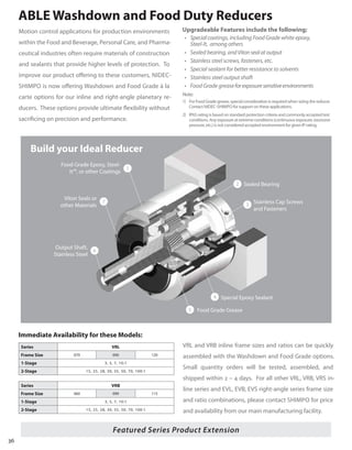
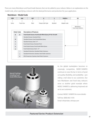
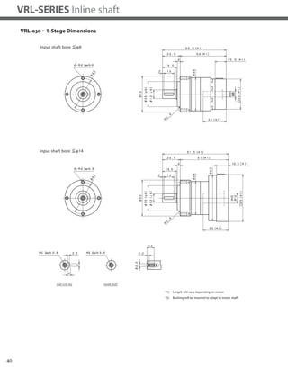
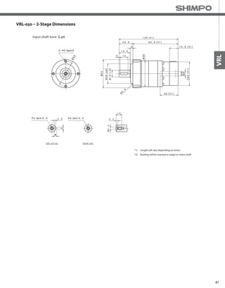
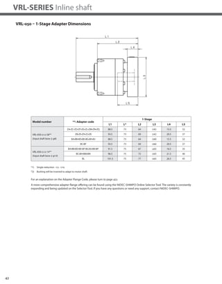
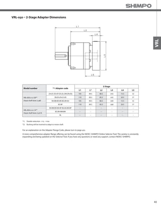
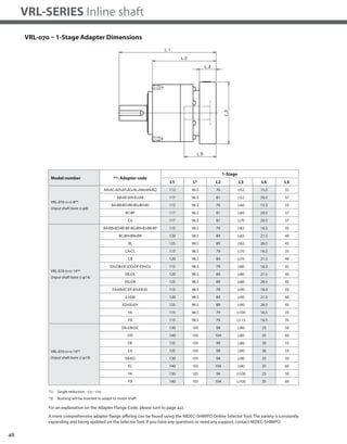
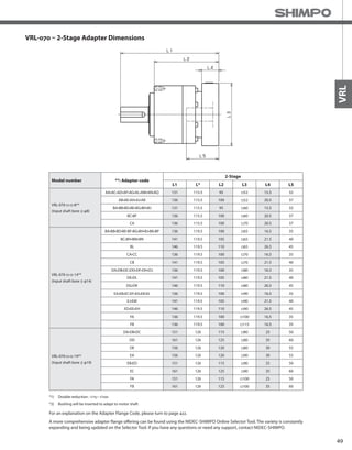
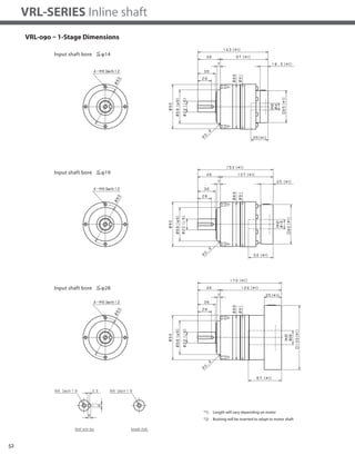
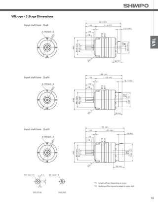
The document provides specifications for the VRL-050 inline planetary gearbox from Nidec-Shimpo. It includes: - Performance specifications like torque ratings, speed ratings, efficiency for 1-stage and 2-stage models in various ratios. - Load ratings for radial force, axial force, moments of inertia. - General specifications covering temperature ratings, noise levels, protection class. - Dimensional drawings and notes on mounting configurations and available options.


