Download to read offline
![Application Scenarios of JINGDIAO Virtual Manufacturing Technology
Technical Points
Mirror the Actual Machining
Environment to Ensure the Accuracy
of Interference Risk Inspection
Informatization of Production
Materials to Avoid Risks Caused by
Wrong Selection of Materials
The Macro Program Fool-Proof to
Avoid Risk Caused by
Mis-Operation by Personnel
Risk Type
Cause Of Risk
Solutions
Z-Axis and Workpiece Tool Holder and Workpiece
Ignore Z-Axis
Complete Machine Model
Spindle and Workpiece
Informatization of Production Materials
Tool Holder Selection
No Informatization of Production Material
Calculation Path
Collision
Tool Holder Selection
Wrong Selection
Map Tool Holder Magazine
No Collision Path Calculation
Tool Clamping Length Error
Tool Setup Foolproof
Logically Judge Whether the Tool Clamping Length is
Within the Safe Value Range
Execution Condition
Implementation Results
Within Safe Range Exceed Safety Value
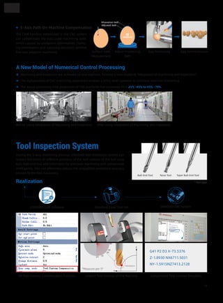
With this software, the program processing, measurement, preparation and logical judgment are combined into one program. The op-
erator only needs to press the start button to begin the processing of the part which reduces machine setup time.
Easy Start
Processing Easy Start
Processing Program Measurement Program Preparation Program
Warm up Machine
Tool Inspection
Warm up Machine
Path Travel Fool-Proof
...
...
M98 P5001(Warm up Machine)
M98 P5002(Tool Inspection)
M98 P5003(Calibration)
M98 P5004(Path Travel Fool-Proof)
M98 P5005(Processing Program)
...
Logical Judgment
If[[#1 Eq 0] || [#2 Eq 0]…[#18
Eq 0]]Go to 1
(Cycle Condition: Unqualified
Remaining Stock at Any Point)
Go to 999
N1 (Execute the Pop-up Program)
G65 P495 A18 (Real-Time
Actual Remaining Stock Displayed
on the Pop-up)
N999
M99
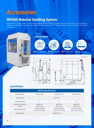
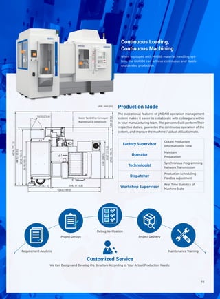
16](https://image.slidesharecdn.com/gra300-201214162237/85/GRA300-5-Axis-Machining-Center-17-320.jpg)
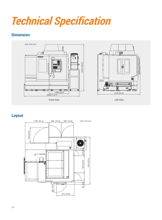
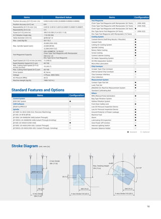

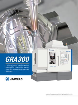
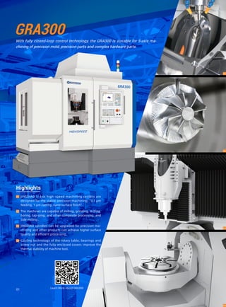
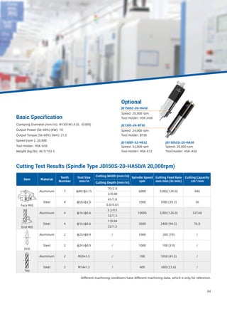
The GRA300 is a 5-axis high-speed machining center designed for precision machining of dies, molds, and complex hardware parts. It has fully closed-loop control for stable 5-axis machining and a maximum workpiece dimension of 390x510x300mm. Optional accessories include various tool magazines and an MHS60 material handling system to enable continuous, unattended production.


