Download to read offline

![18
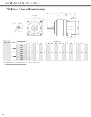
VRSF-SERIES Inline shaft
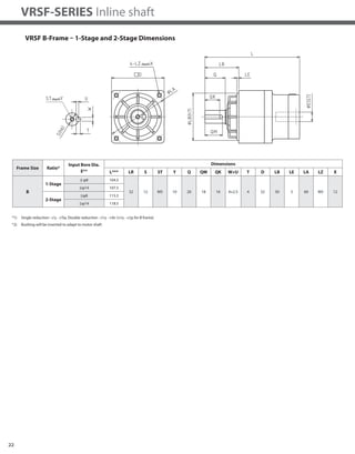
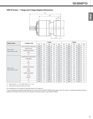
VRSF B-Frame – 1-Stage and 2-Stage Specifications
Frame Size B
Stage 1-Stage 2-Stage
Ratio Units Note 3 5 9 15 20 25 35
Nominal Output Torque [Nm] -- 3.43 2.84 2.35 4.02 5.00 6.27 3.84
Maximum Acceleration Torque [Nm] -- 10.3 8.53 7.25 12.2 15.0 19.0 11.5
Emergency Stop Torque [Nm] -- -- -- -- -- -- -- --
Nominal Input Speed [rpm] -- 3000 3000
Maximum Input Speed [rpm] *1 5000 5000
No Load Running Torque [Nm] -- 0.119 0.048
Permitted Radial Load [N] *2 392 490 588 784 804 882 882
Permitted Axial Load [N] *3 196 245 294 392 402 441 441
Moment of Inertia (≤Ø 8) [kgcm2] *4 0.081 0.059 0.052 0.057 0.056 0.056 0.052
Moment of Inertia (≤Ø 14) [kgcm2] *4 0.150 0.130 0.120 0.130 0.130 0.130 0.120
Efficiency [%] -- 90 85
Torsional Rigidity [Nm/arcmin] -- 0.8 0.8
Backlash (Standard) [Arc-min] -- ≤ 15 ≤ 15
Backlash (Low) [Arc-min] -- ≤ 10 ≤ 10
Backlash (Precision) [Arc-min] -- ≤ 3 ≤ 3
Noise Level [dB] -- ≤ 72 ≤ 65
Protection Class -- -- IP65 IP65
Ambient Temperature [°C] -- 0-40 0-40
Permitted Housing Temperature [°C] -- 90 90
Weight (≤Ø 8) [kg] *5 0.58 0.75
Weight (≤Ø 14) [kg] *5 0.7 0.86
*1) Nominal input speed is 3,000 rpm or less
*2) Permitted radial load is measured at the middle of the output shaft
*3) Permitted thrust load is measured at the center of the output shaft
*4) The moment of inertia is reflected to the input shaft of the reducer
*5) The weight varies slightly depending on the input bore size and reduction ratio
Refer to page 30-31 for Metric and NEMA Output Flange](https://image.slidesharecdn.com/shimpovrsf-series-140807090526-phpapp01/85/Shimpo-vrsf-series-5-320.jpg)
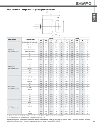
![19
VRSF
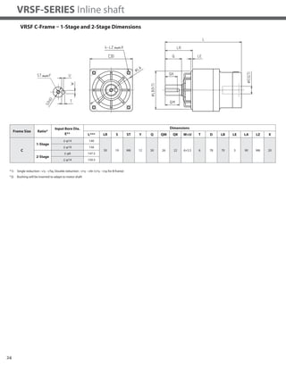
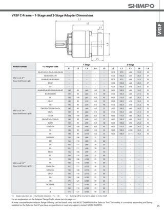
VRSF C-Frame – 1-Stage and 2-Stage Specifications
Frame Size C
Stage 1-Stage 2-Stage
Ratio Units Note 3 5 9 15 20 25 35 45 81
Nominal Output Torque [Nm] -- 6.86 11.5 9.7 16.2 21.1 26.4 15.5 9.5 9.7
Maximum Acceleration Torque [Nm] -- 20.6 34.3 29.2 48.6 63.3 79.2 46.6 28.6 29.2
Emergency Stop Torque [Nm] -- -- -- -- -- -- -- -- -- --
Nominal Input Speed [rpm] -- 3000 3000
Maximum Input Speed [rpm] *1 5000 5000
No Load Running Torque [Nm] -- 0.29 0.19
Permitted Radial Load [N] *2 784 980 1180 1470 1570 1670 1670 1670 1670
Permitted Axial Load [N] *3 392 490 588 735 785 833 833 833 833
Moment of Inertia (≤Ø 8) [kgcm2] *4 -- -- -- 0.077 0.070 0.062 0.055 0.053 0.052
Moment of Inertia (≤Ø 14) [kgcm2] *4 0.630 0.380 0.300 0.150 0.140 0.130 0.130 0.120 0.120
-- -- *4 1.100 0.880 0.800 -- -- -- -- -- --
Efficiency [%] -- 90 85
Torsional Rigidity [Nm/arcmin] -- 3 3
Backlash (Standard) [Arc-min] -- ≤ 15 ≤ 15
Backlash (Low) [Arc-min] -- ≤ 5 ≤ 5
Backlash (Precision) [Arc-min] -- ≤ 3 ≤ 3
Noise Level [dB] -- ≤ 72 ≤ 65
Protection Class -- -- IP 65 IP65
Ambient Temperature [°C] -- 0-40 0-40
Permitted Housing Temperature [°C] -- 90 90
Weight (≤Ø 8) [kg] *5 -- 1.8
Weight (≤Ø 14) [kg] *5 1.8 1.9
Weight (≤Ø 19) -- -- 2.2 --
*1) Nominal input speed is 3,000 rpm or less
*2) Permitted radial load is measured at the middle of the output shaft
*3) Permitted thrust load is measured at the center of the output shaft
*4) The moment of inertia is reflected to the input shaft of the reducer
*5) The weight varies slightly depending on the input bore size and reduction ratio
Refer to page 30-31 for Metric and NEMA Output Flange](https://image.slidesharecdn.com/shimpovrsf-series-140807090526-phpapp01/85/Shimpo-vrsf-series-6-320.jpg)
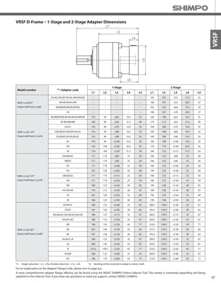
![20
VRSF-SERIES Inline shaft
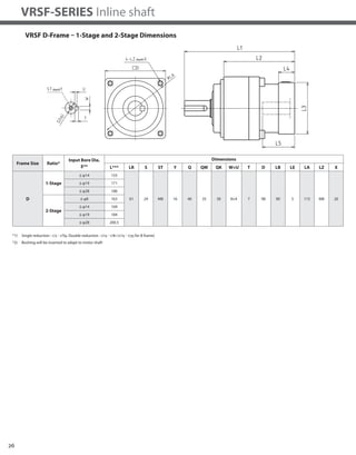
VRSF D-Frame – 1-Stage and 2-Stage Specifications
*1) Nominal input speed is 3,000 rpm or less
*2) Permitted radial load is measured at the middle of the output shaft
*3) Permitted thrust load is measured at the center of the output shaft
*4) The moment of inertia is reflected to the input shaft of the reducer
*5) The weight varies slightly depending on the input bore size and reduction ratio
Frame Size D
Stage 1-Stage 2-Stage
Ratio Units Note 3 5 9 15 20 25 35 45 81
Nominal Output Torque [Nm] -- 18.3 23.5 18.2 30.4 40.6 50.7 37 28.3 17.8
Maximum Acceleration Torque [Nm] -- 54.9 70.6 54.7 91.2 122 152 111 85.2 53.5
Emergency Stop Torque [Nm] -- -- -- -- -- -- -- -- -- --
Nominal Input Speed [rpm] -- 3000 3000
Maximum Input Speed [rpm] *1 5000 5000
No Load Running Torque [Nm] -- 0.51 0.26
Permitted Radial Load [N] *2 882 1080 1470 1760 1910 2060 2060 2060 2060
Permitted Axial Load [N] *3 441 539 735 882 955 1030 1030 1030 1030
Moment of Inertia (≤Ø 8) [kgcm2] *4 -- -- -- -- -- -- -- -- 0.10
Moment of Inertia (≤Ø 14) [kgcm2] *4 1.30 0.59 0.38 0.37 0.35 0.34 0.30 0.29 0.29
Moment of Inertia (≤Ø 19) [kgcm2] *4 1.80 1.10 0.90 0.86 0.84 0.83 0.79 0.78 0.77
Moment of Inertia (≤Ø 28) [kgcm2] *4 3.60 2.90 2.70 2.70 2.70 2.70 -- -- --
Efficiency [%] -- 90 85
Torsional Rigidity [Nm/arcmin] -- 6 6
Backlash (Standard) [Arc-min] -- ≤ 15 ≤ 15
Backlash (Low) [Arc-min] -- ≤ 5 ≤ 5
Backlash (Precision) [Arc-min] -- ≤ 3 ≤ 3
Noise Level [dB] -- ≤ 72 ≤ 65
Protection Class -- -- IP65 IP65
Ambient Temperature [°C] -- 0-40 0-40
Permitted Housing Temperature [°C] -- 90 90
Weight (≤Ø 8) [kg] *5 -- 2.8
Weight (≤Ø 14) [kg] *5 2.8 3.3
Weight (≤Ø 19) [kg] *5 3.2 3.7
Weight (≤Ø 28) [kg] *5 4.0 4.8
Refer to page 30-31 for Metric and NEMA Output Flange](https://image.slidesharecdn.com/shimpovrsf-series-140807090526-phpapp01/85/Shimpo-vrsf-series-7-320.jpg)
![21
VRSF
VRSF E-Frame – 1-Stage and 2-Stage Specifications
*1) Nominal input speed is 3,000 rpm or less
*2) Permitted radial load is measured at the middle of the output shaft
*3) Permitted thrust load is measured at the center of the output shaft
*4) The moment of inertia is reflected to the input shaft of the reducer
*5) The weight varies slightly depending on the input bore size and reduction ratio
Frame Size E
Stage 1-Stage 2-Stage
Ratio Units Note 3 5 9 15 20 25 35 45 81
Nominal Output Torque [Nm] -- 44.1 56.8 73.5 91.4 78.4 65.4 71 91.3 43.3
Maximum Acceleration Torque [Nm] -- 132 171 221 274 235 196 213 274 130
Emergency Stop Torque [Nm] -- -- -- -- -- -- -- -- -- --
Nominal Input Speed [rpm] -- 3000 3000
Maximum Input Speed [rpm] *1 5000 5000
No Load Running Torque [Nm] -- 1.12 0.62
Permitted Radial Load [N] *2 1370 1670 1960 2350 2500 2650 3430 3520 3530
Permitted Axial Load [N] *3 686 833 980 1180 1250 1320 1715 1760 1765
Moment of Inertia (≤Ø 8) [kgcm2] *4 -- -- 0.61 0.63 0.56 0.53 0.40 0.35 0.34
Moment of Inertia (≤Ø 14) [kgcm2] *4 4.40 1.90 1.20 1.10 1.10 1.00 0.90 0.85 0.84
Moment of Inertia (≤Ø 19) [kgcm2] *4 6.20 3.70 2.90 3.30 3.20 3.20 2.80 2.70 2.70
Moment of Inertia (≤Ø 28) [kgcm2] *4 14.00 11.00 11.00 11.00 11.00 11.00 -- -- --
Efficiency [%] -- 90 85
Torsional Rigidity [Nm/arcmin] -- 20 20
Backlash (Standard) [Arc-min] -- ≤ 15 ≤ 15
Backlash (Low) [Arc-min] -- ≤ 5 ≤ 5
Backlash (Precision) [Arc-min] -- ≤ 3 ≤ 3
Noise Level [dB] -- ≤ 75 ≤ 75
Protection Class -- -- IP65 IP65
Ambient Temperature [°C] -- 0-40 0-40
Permitted Housing Temperature [°C] -- 90 90
Weight (≤Ø 8) [kg] *5 6.1 7.1
Weight (≤Ø 14) [kg] *5 6.5 7.5
Weight (≤Ø 19) [kg] *5 7.4 9.3
Weight (≤Ø 28) [kg] *5 9.8 11.7
Refer to page 30-31 for Metric and NEMA Output Flange](https://image.slidesharecdn.com/shimpovrsf-series-140807090526-phpapp01/85/Shimpo-vrsf-series-8-320.jpg)

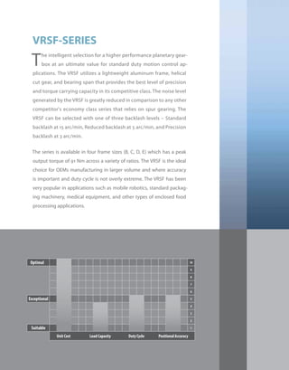
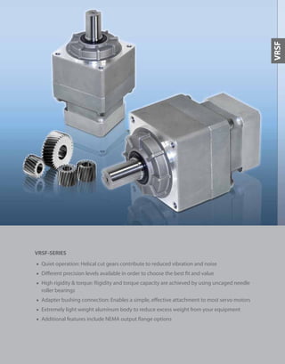
The document discusses the VRSF-Series planetary gearbox from Nidec-Shimpo. It provides specifications for the gearbox including its lightweight aluminum frame, helical cut gears, precision levels available, noise reduction, and torque capacity. It also summarizes the available frame sizes, ratios, backlash levels, and applications for the gearbox, which include robotics, packaging machinery, medical equipment, and enclosed food processing.


![5G Explained! A High Level Overview [Introduction]](https://cdn.slidesharecdn.com/ss_thumbnails/5gexplainedahighleveloverview-260119165306-cc137a3e-thumbnail.jpg?width=640&height=640&fit=bounds)


