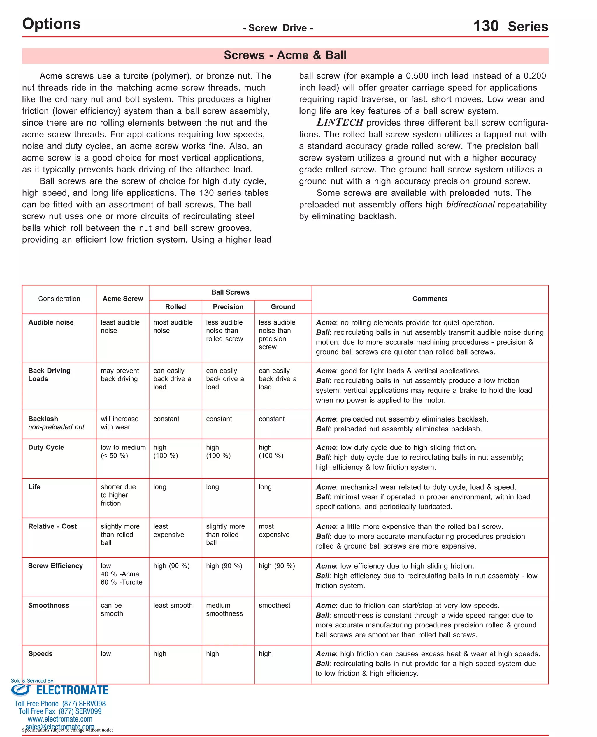
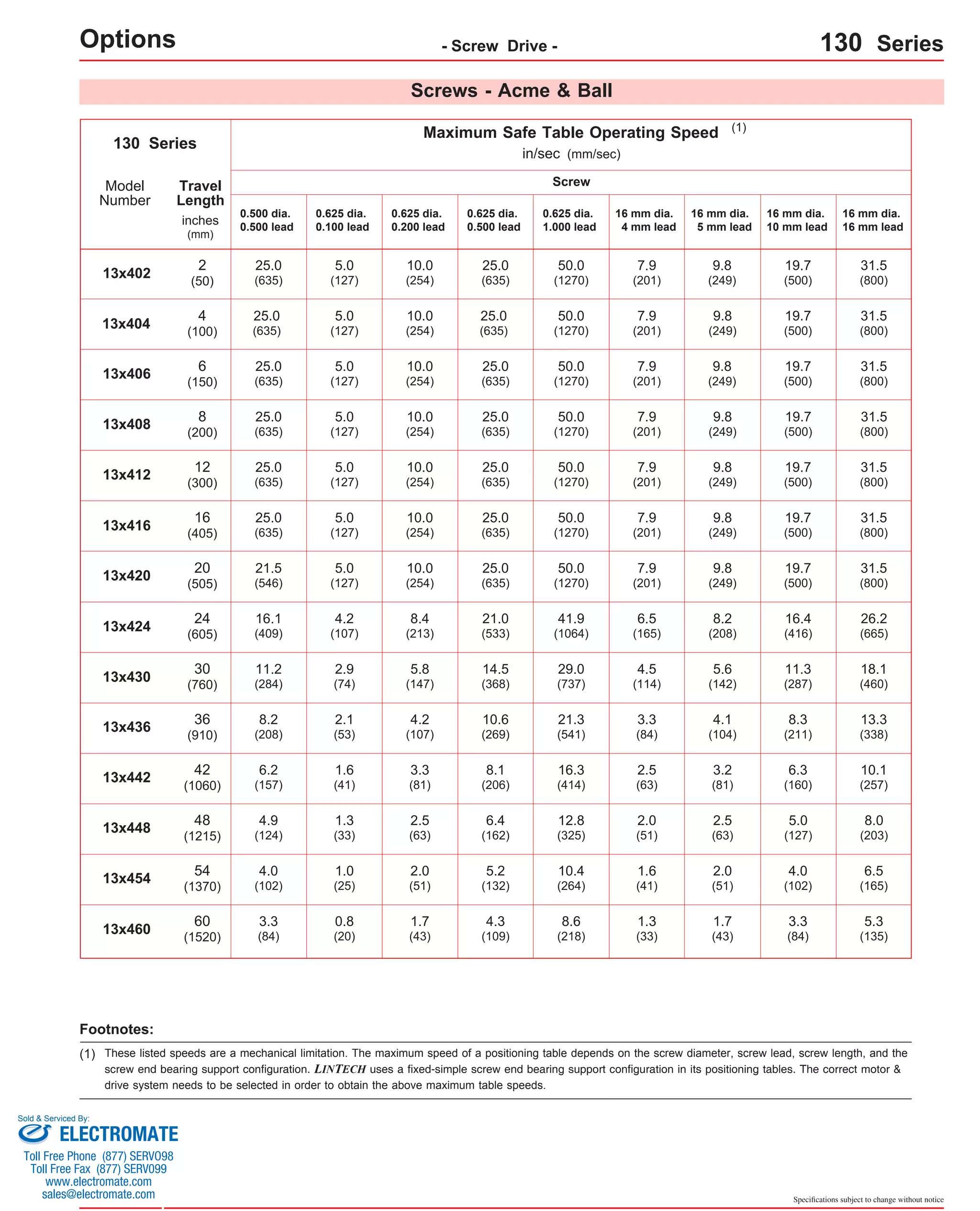
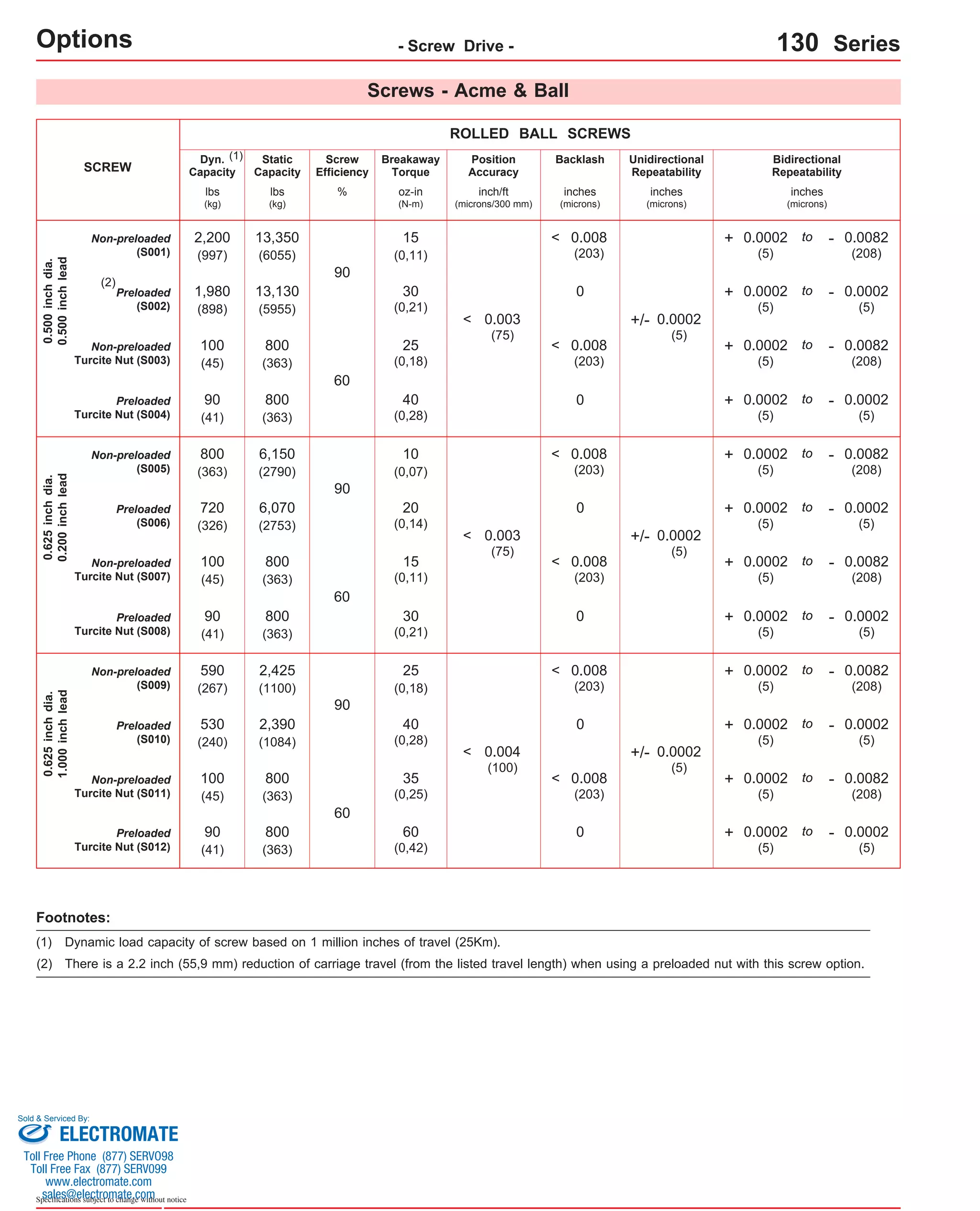
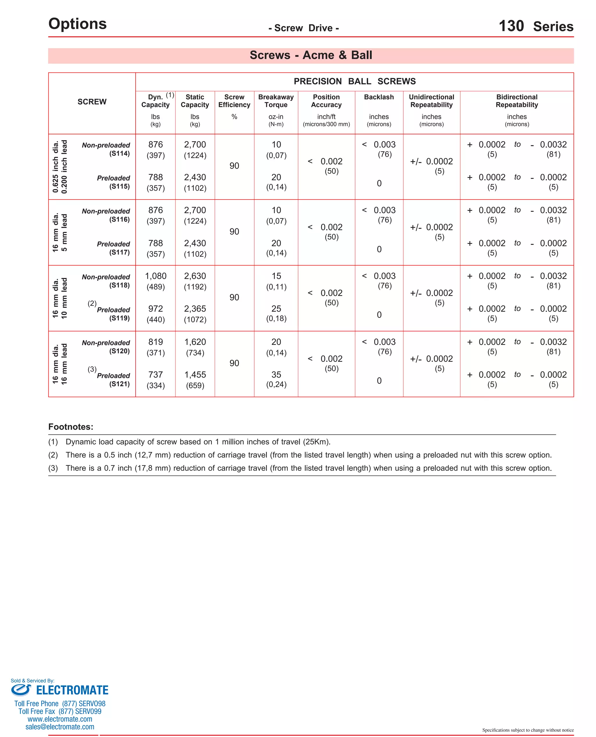
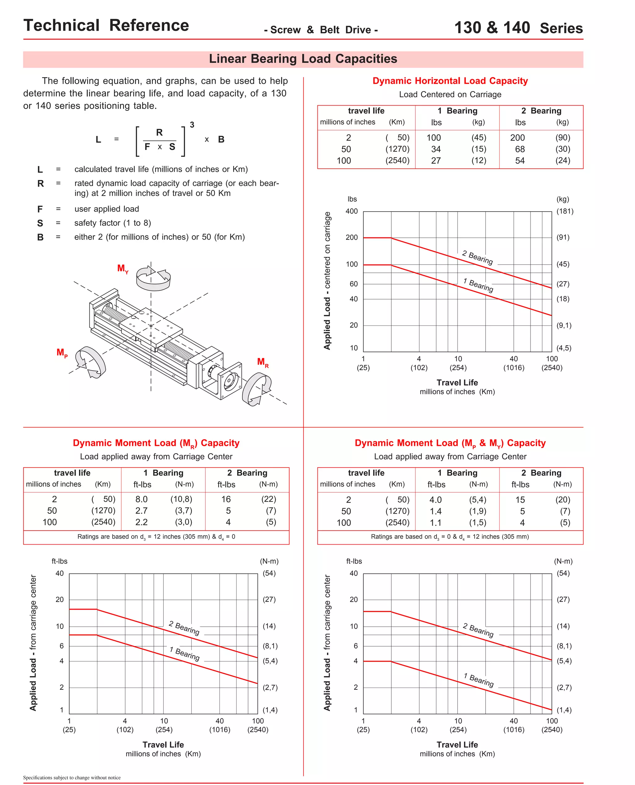
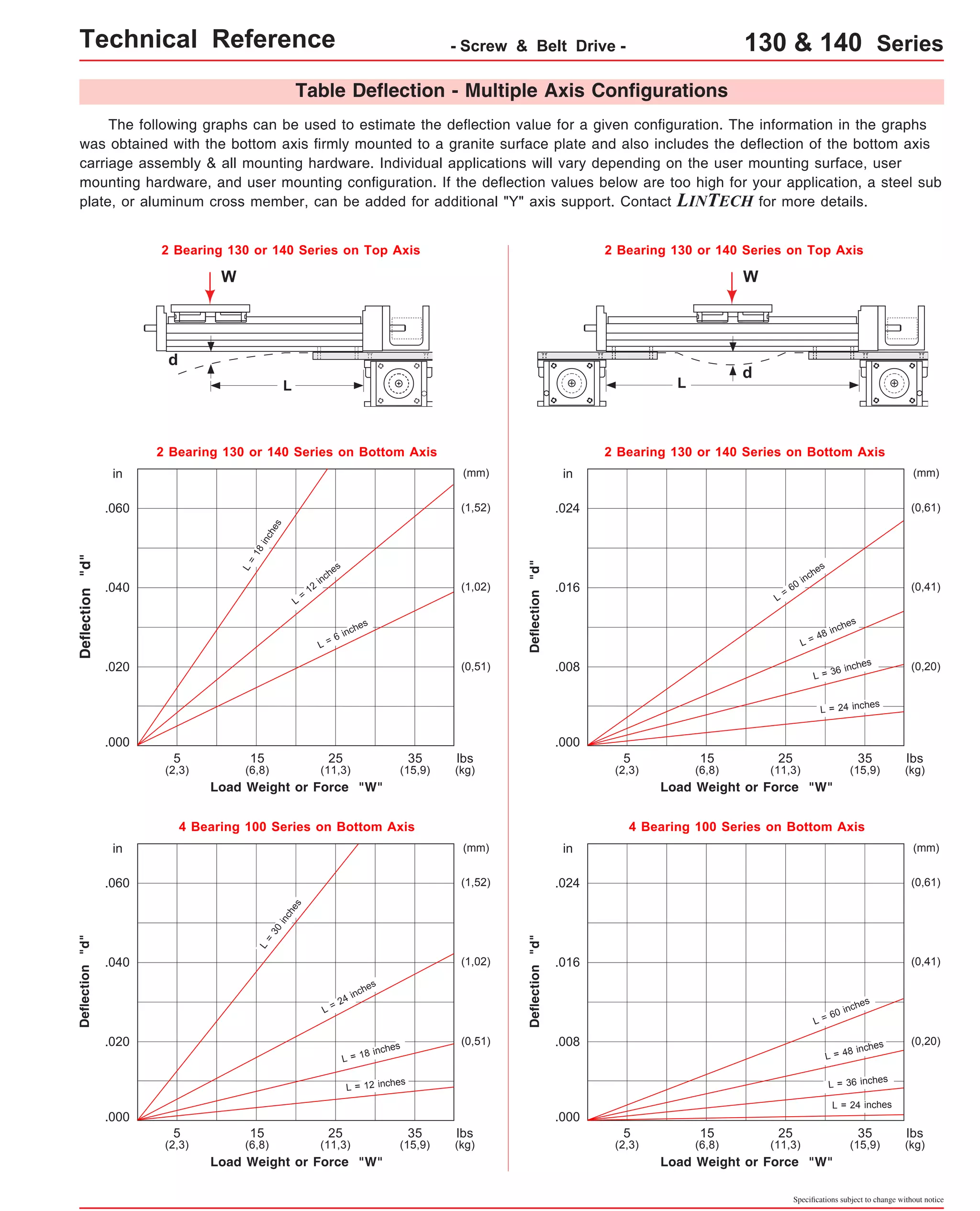
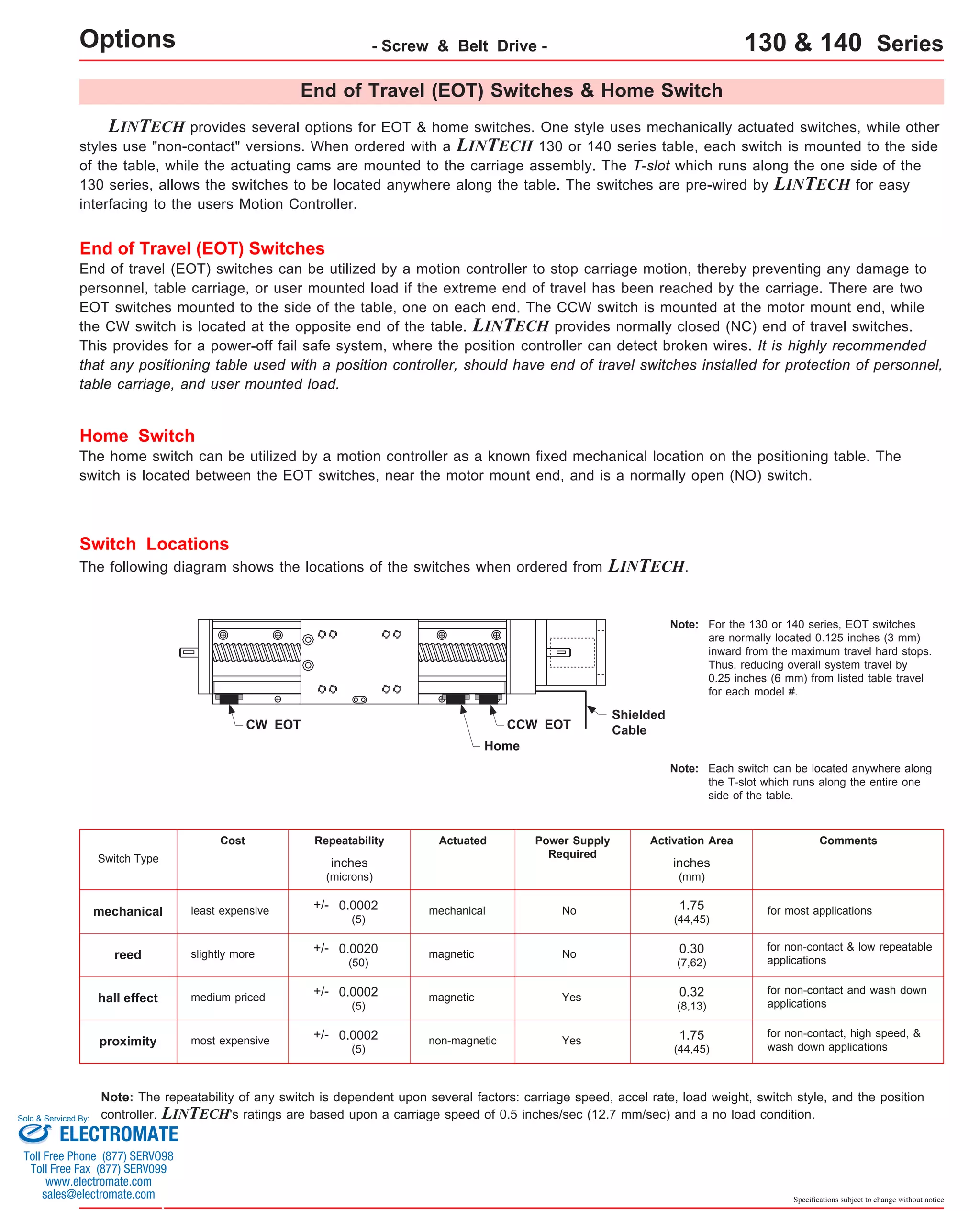
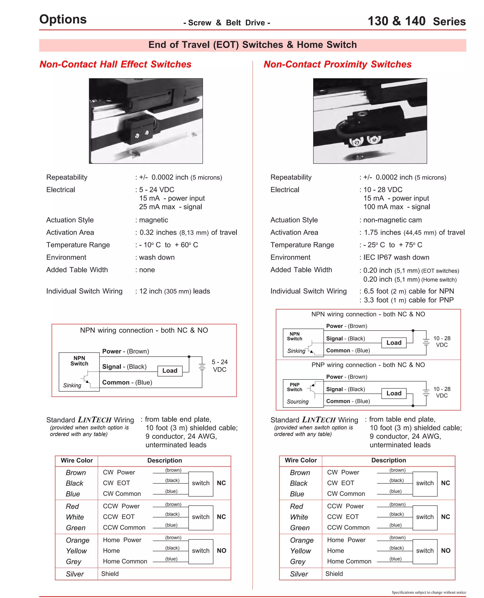
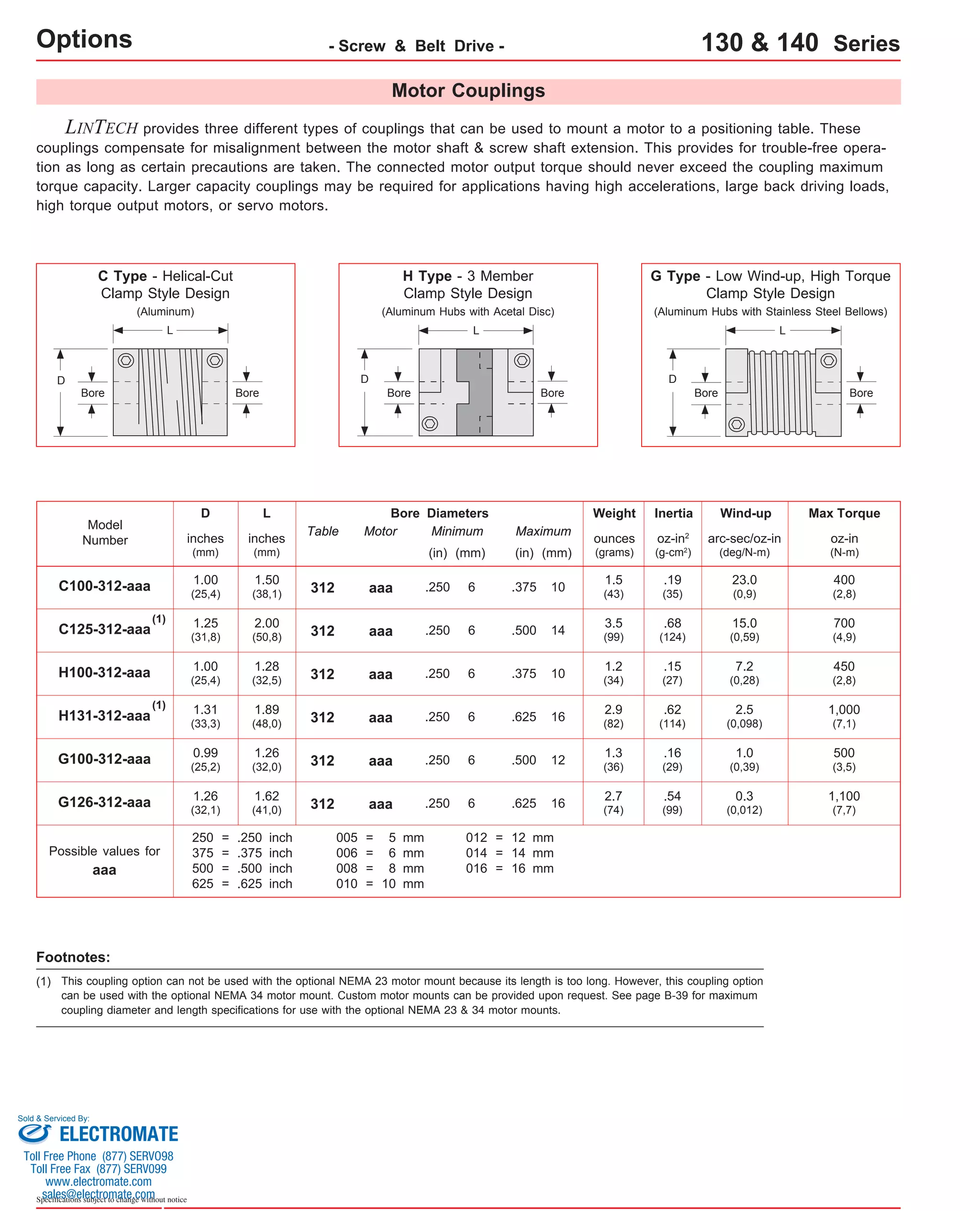
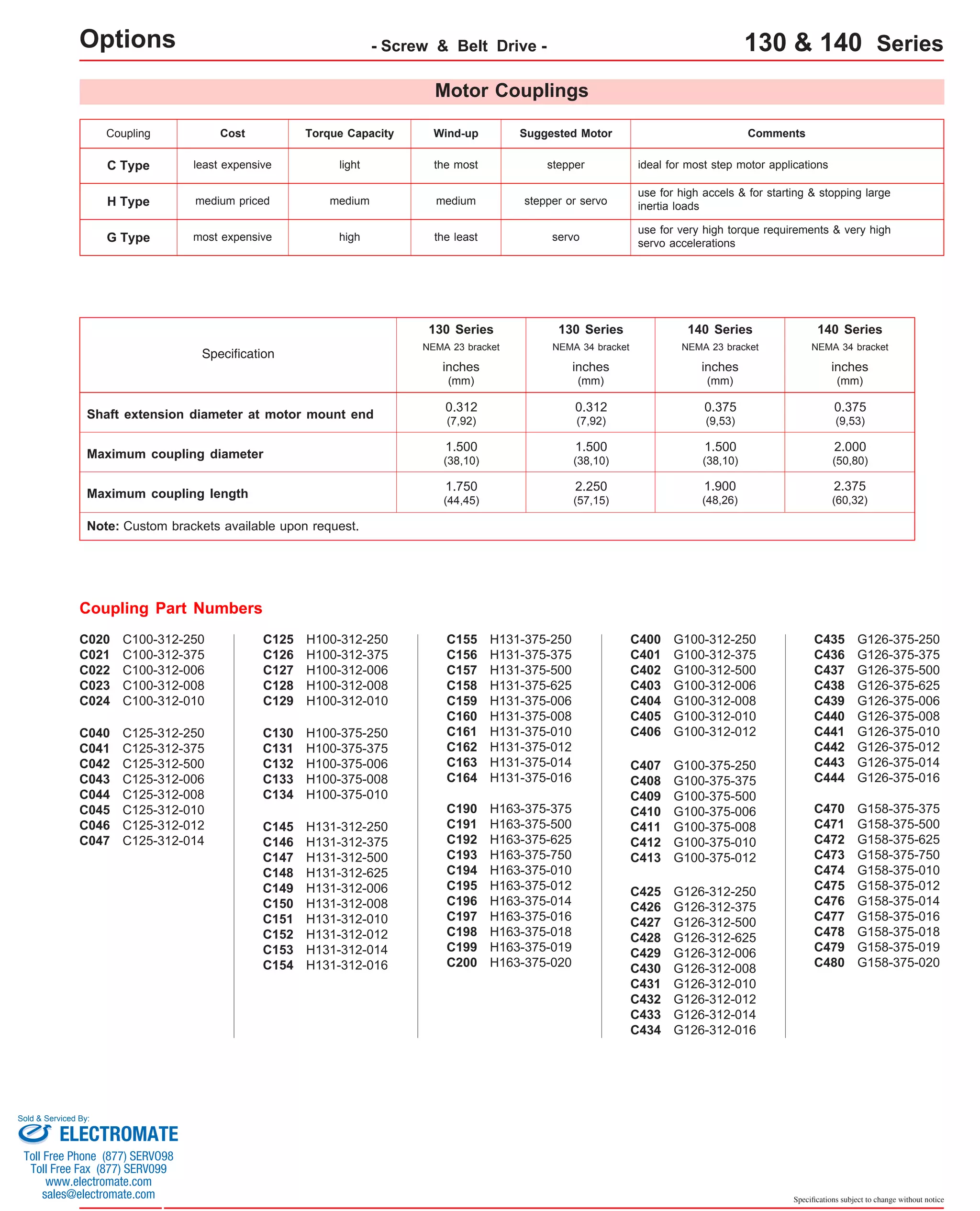
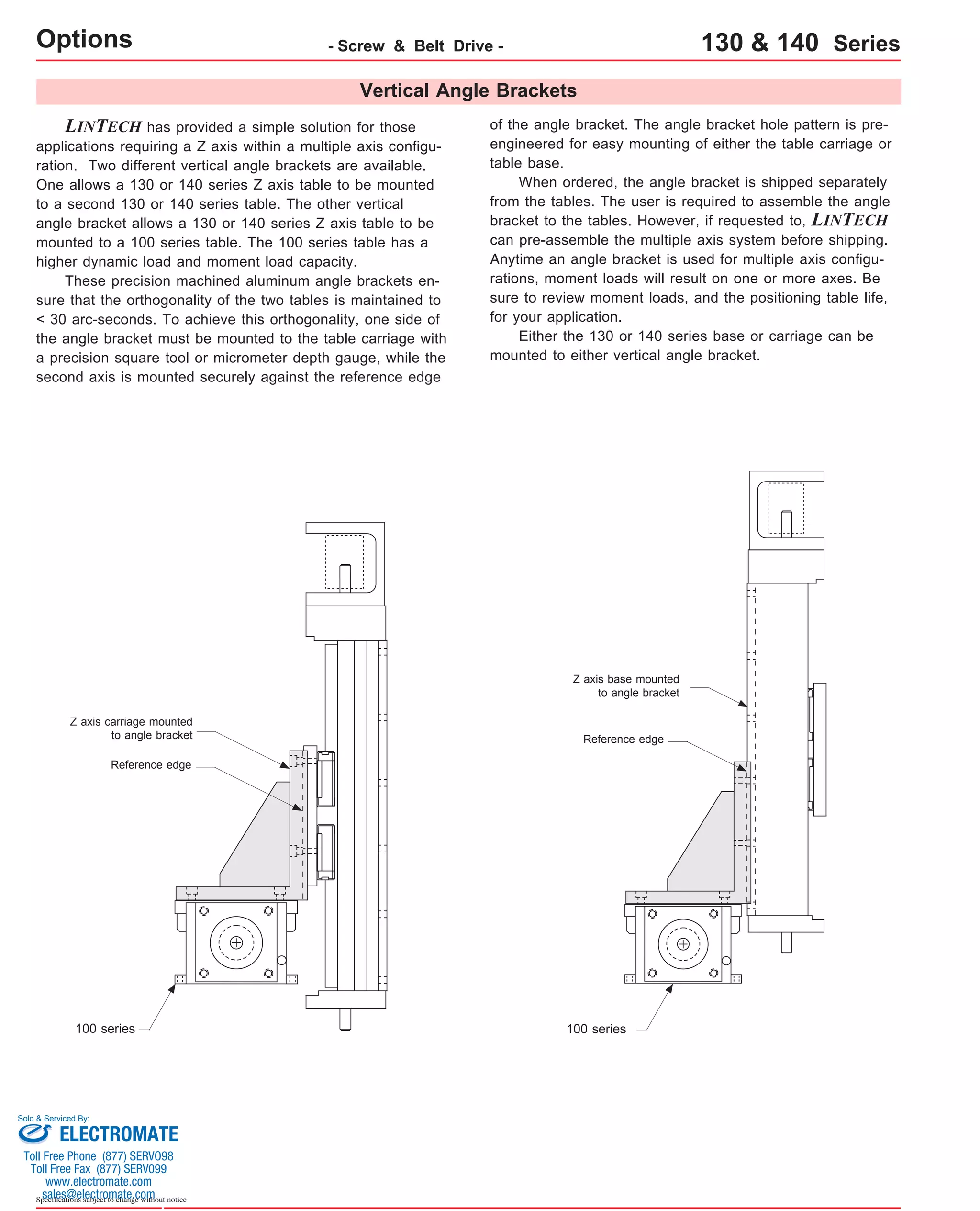
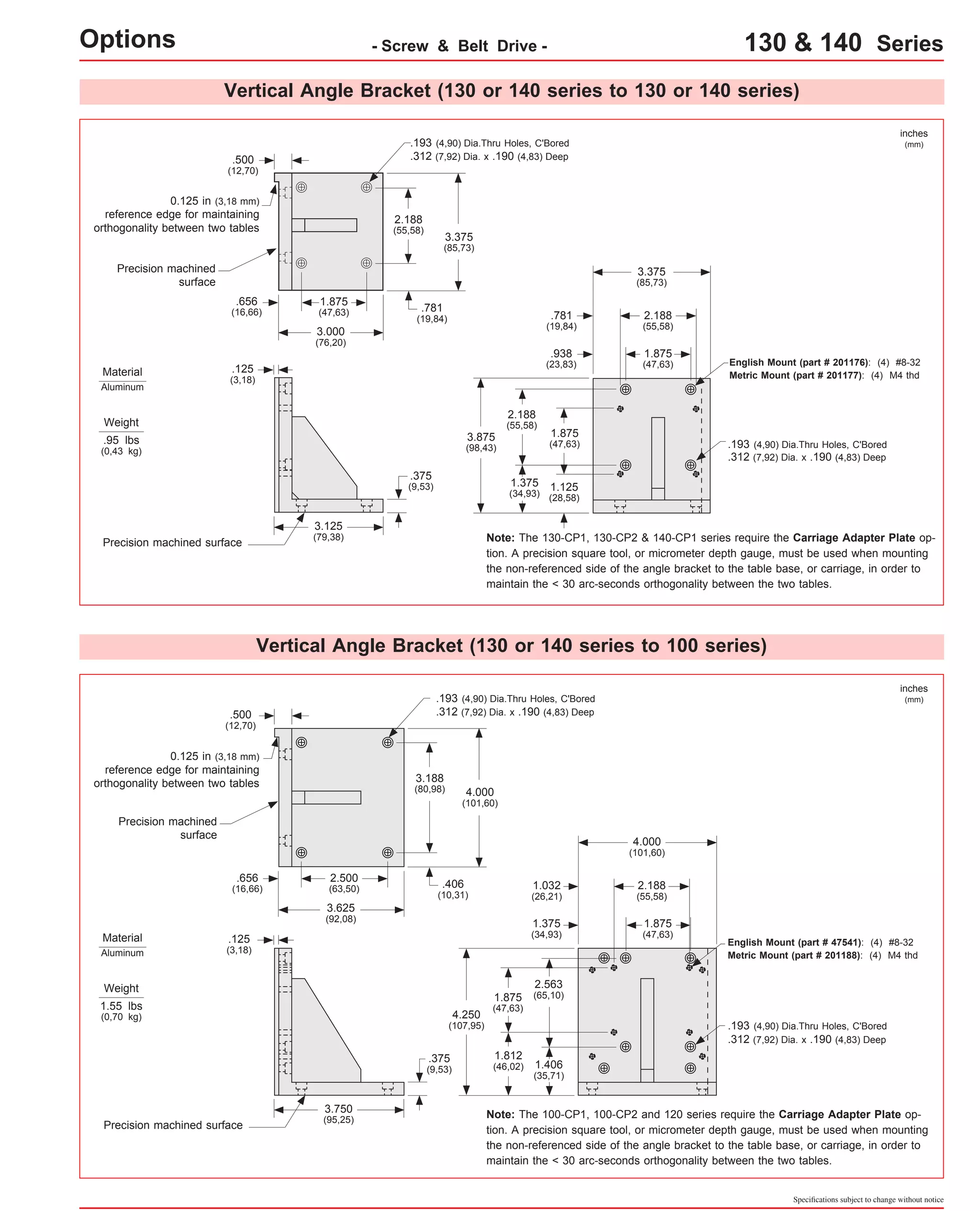
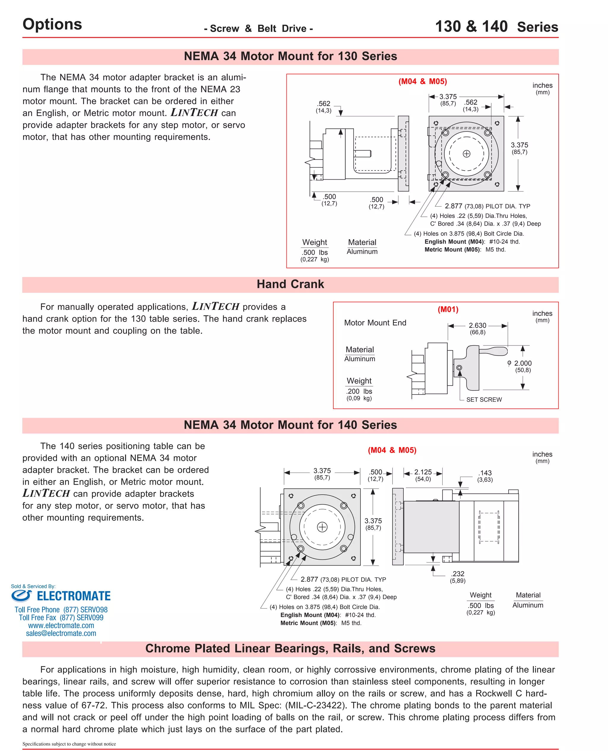
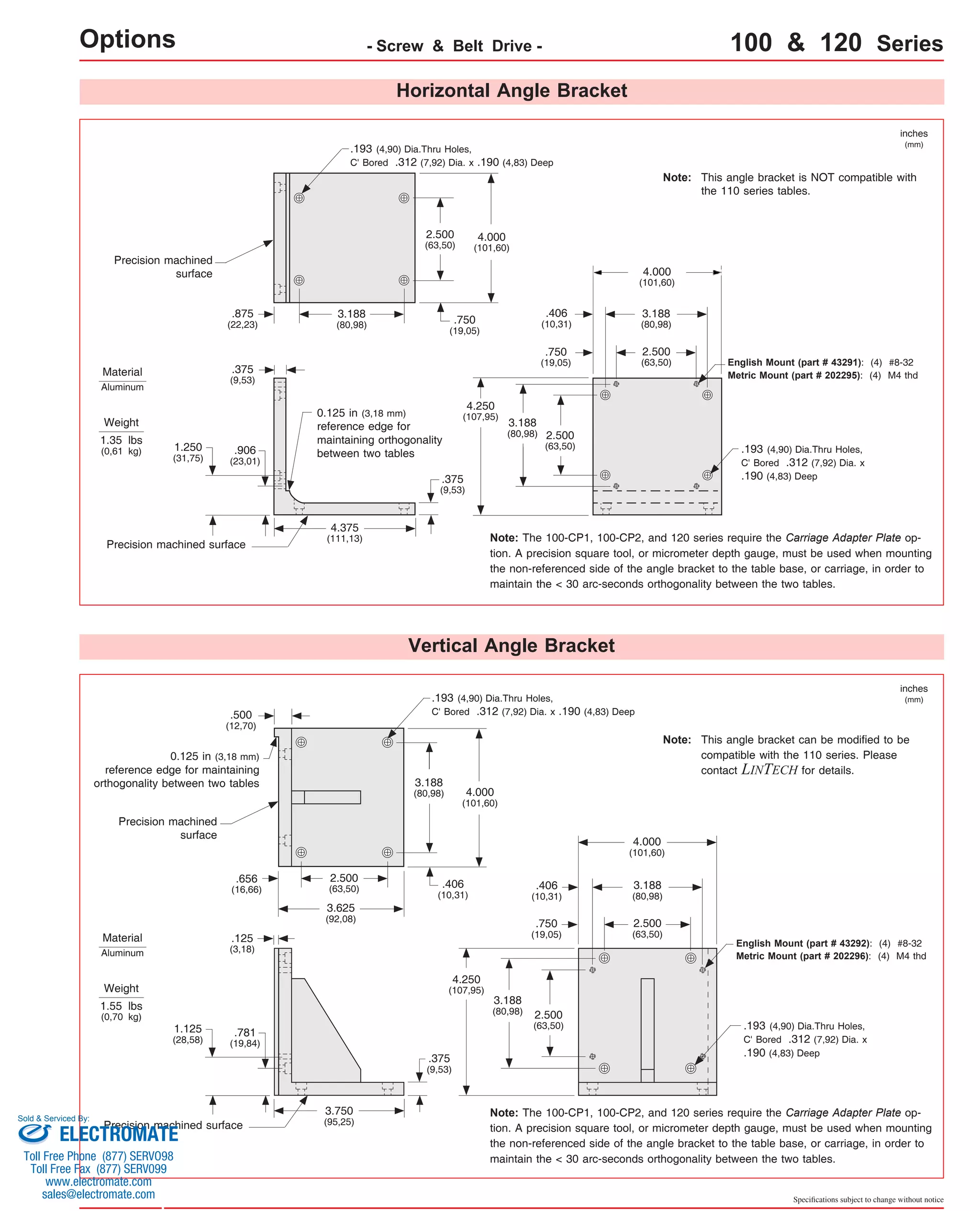
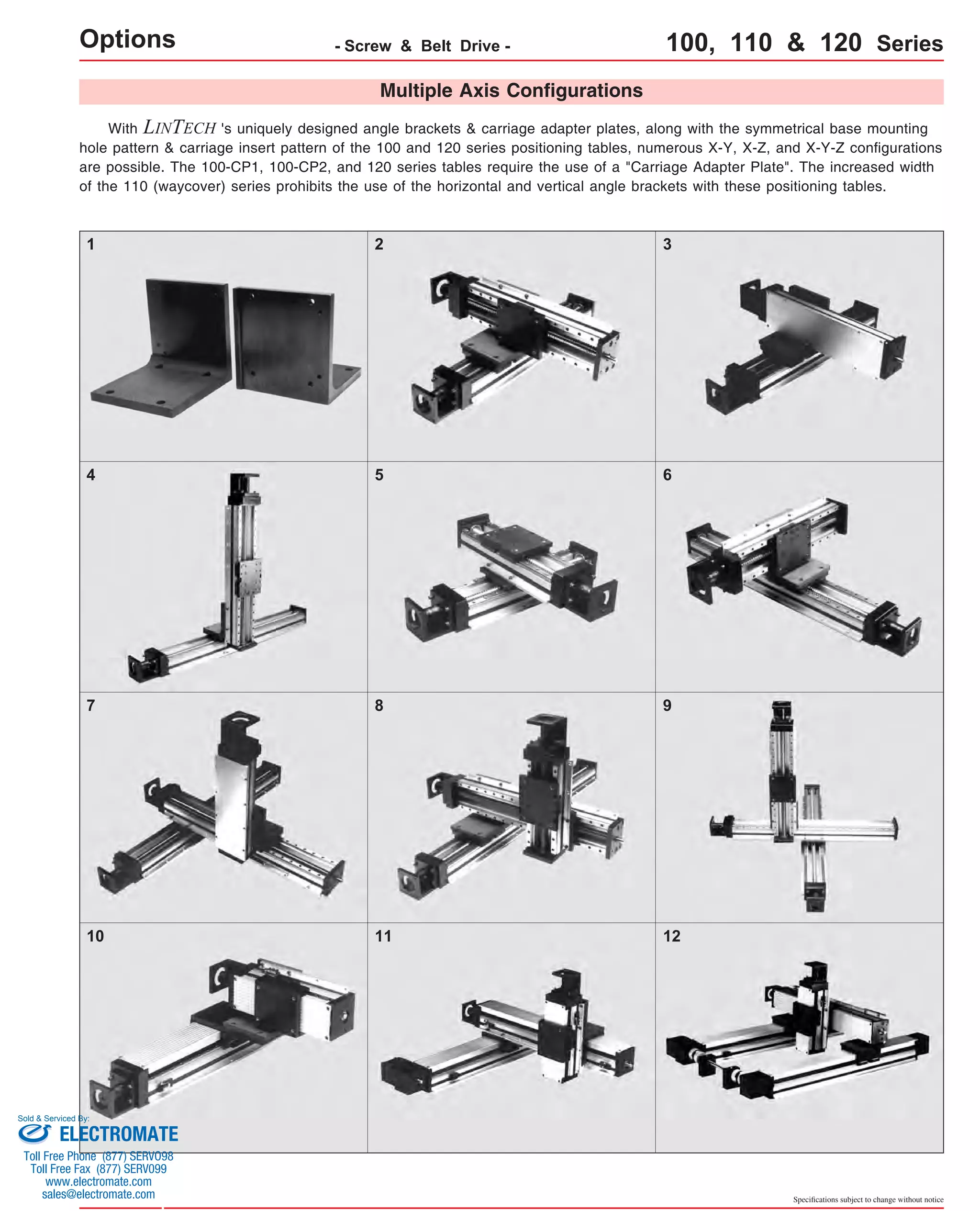
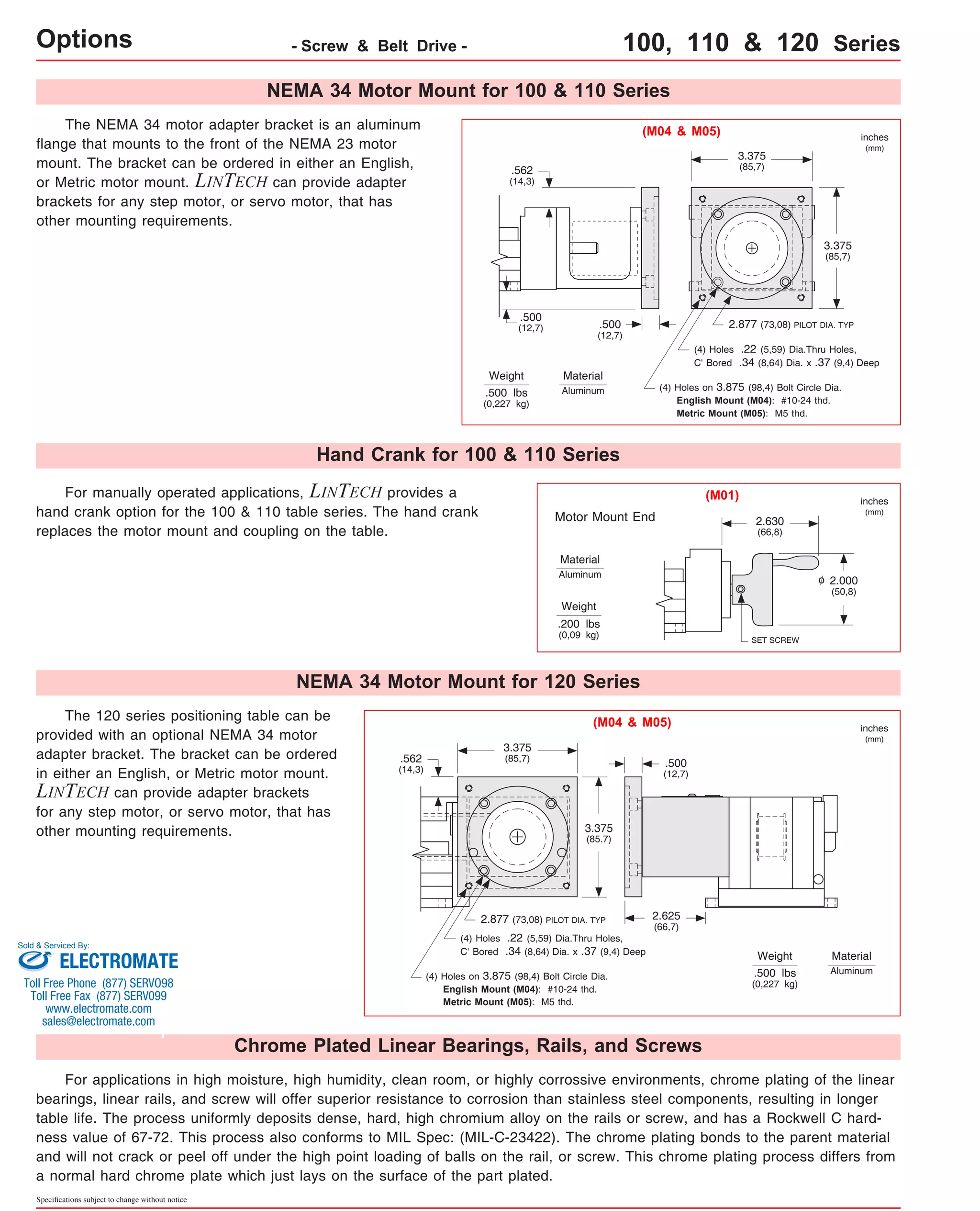
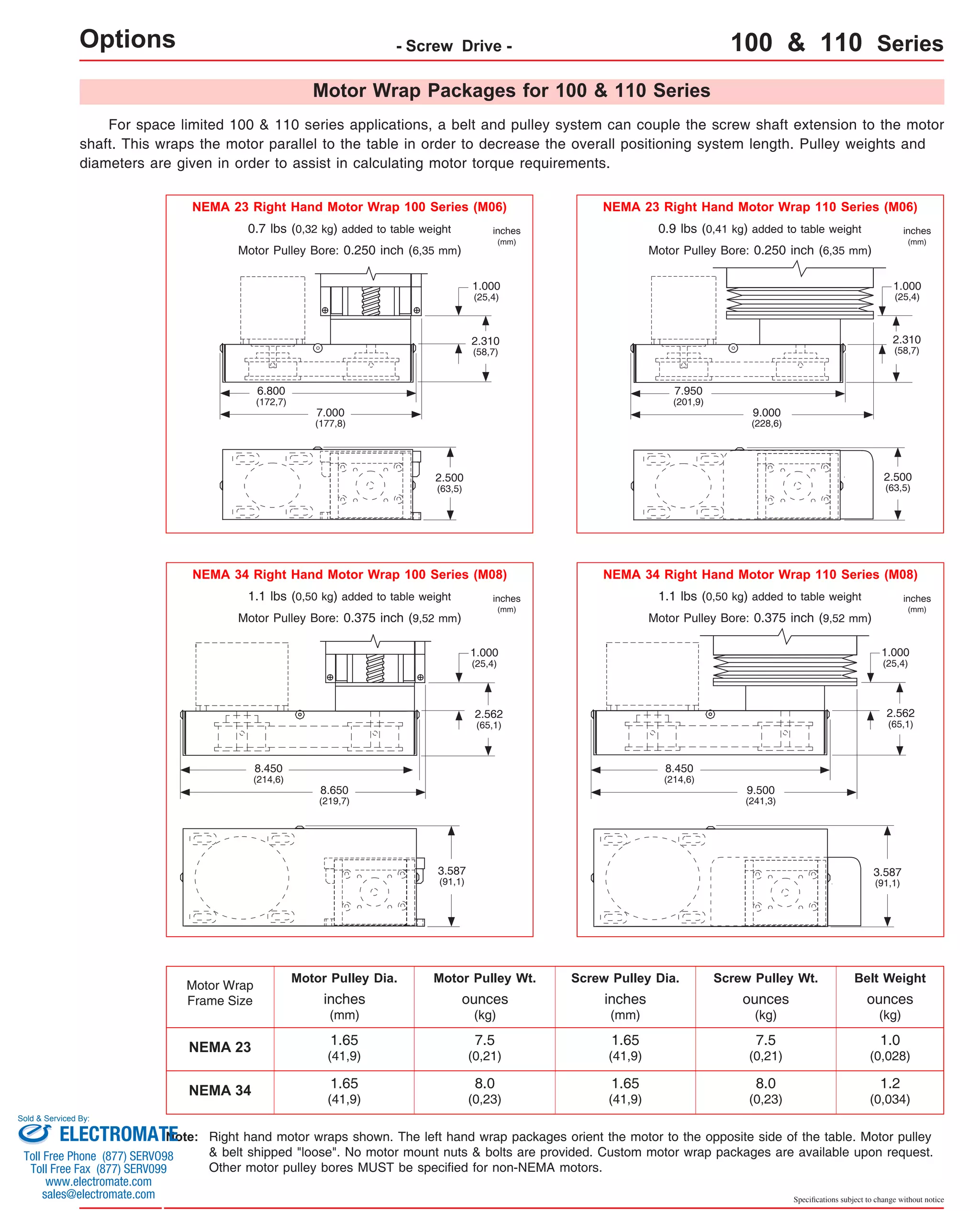
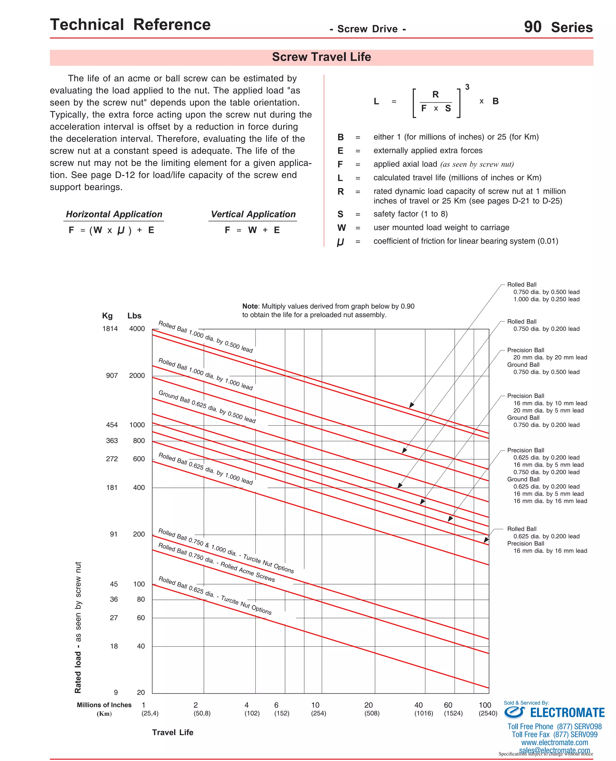
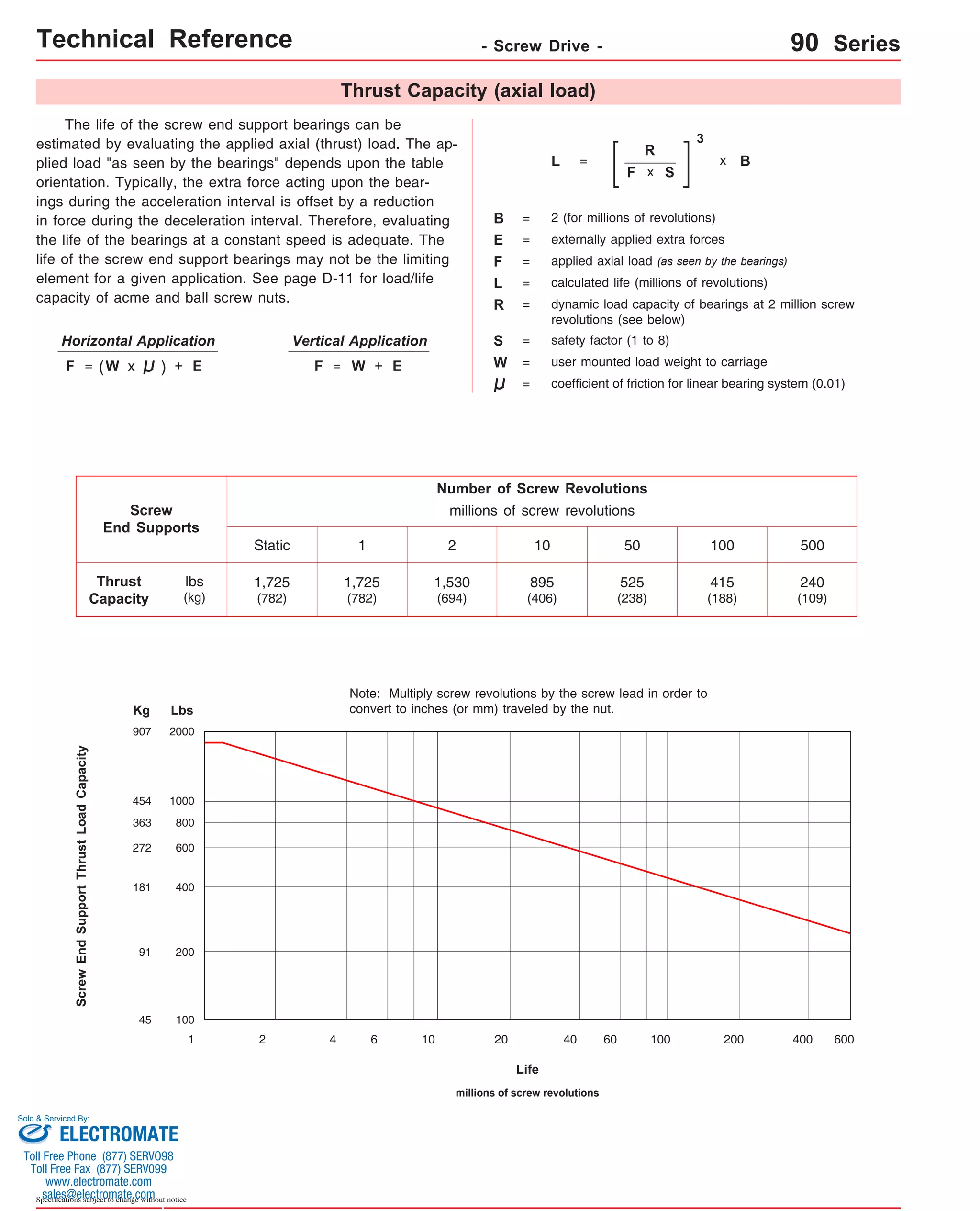
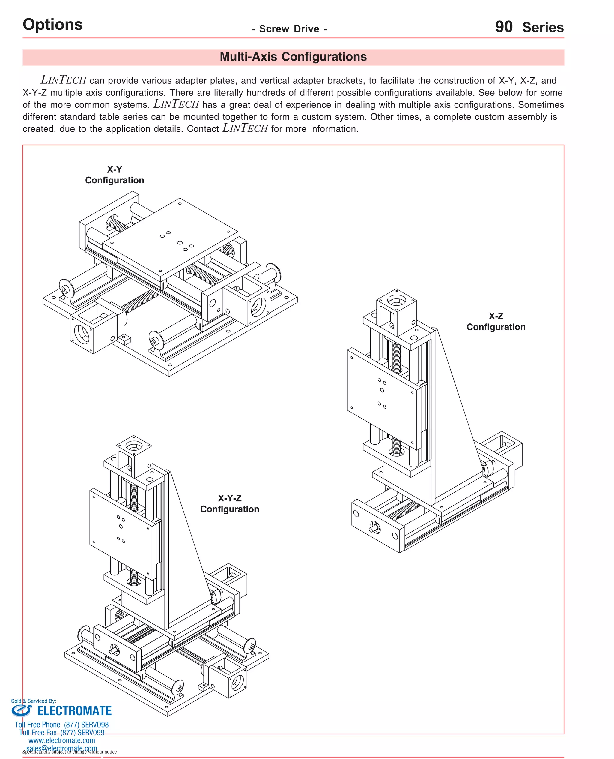
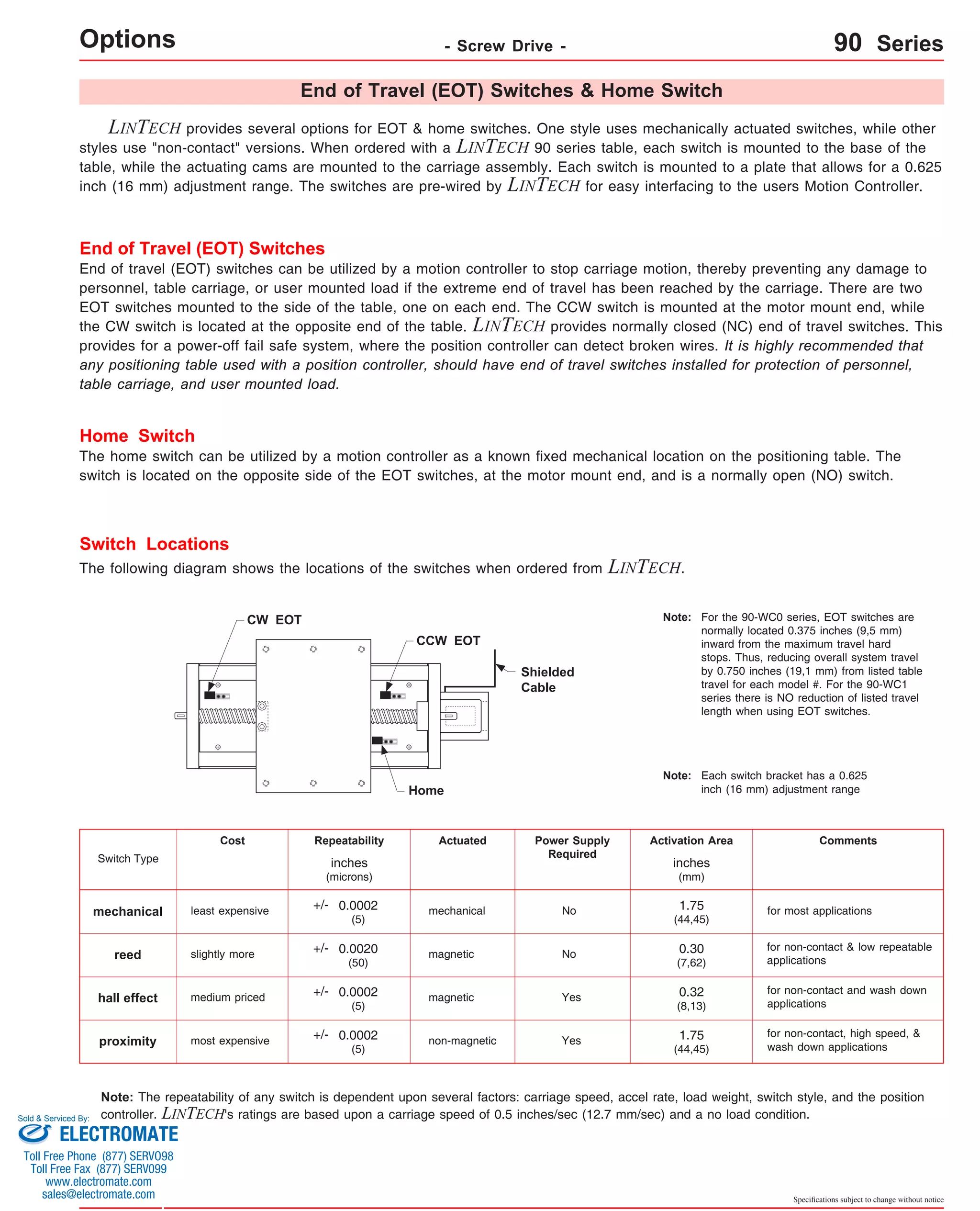
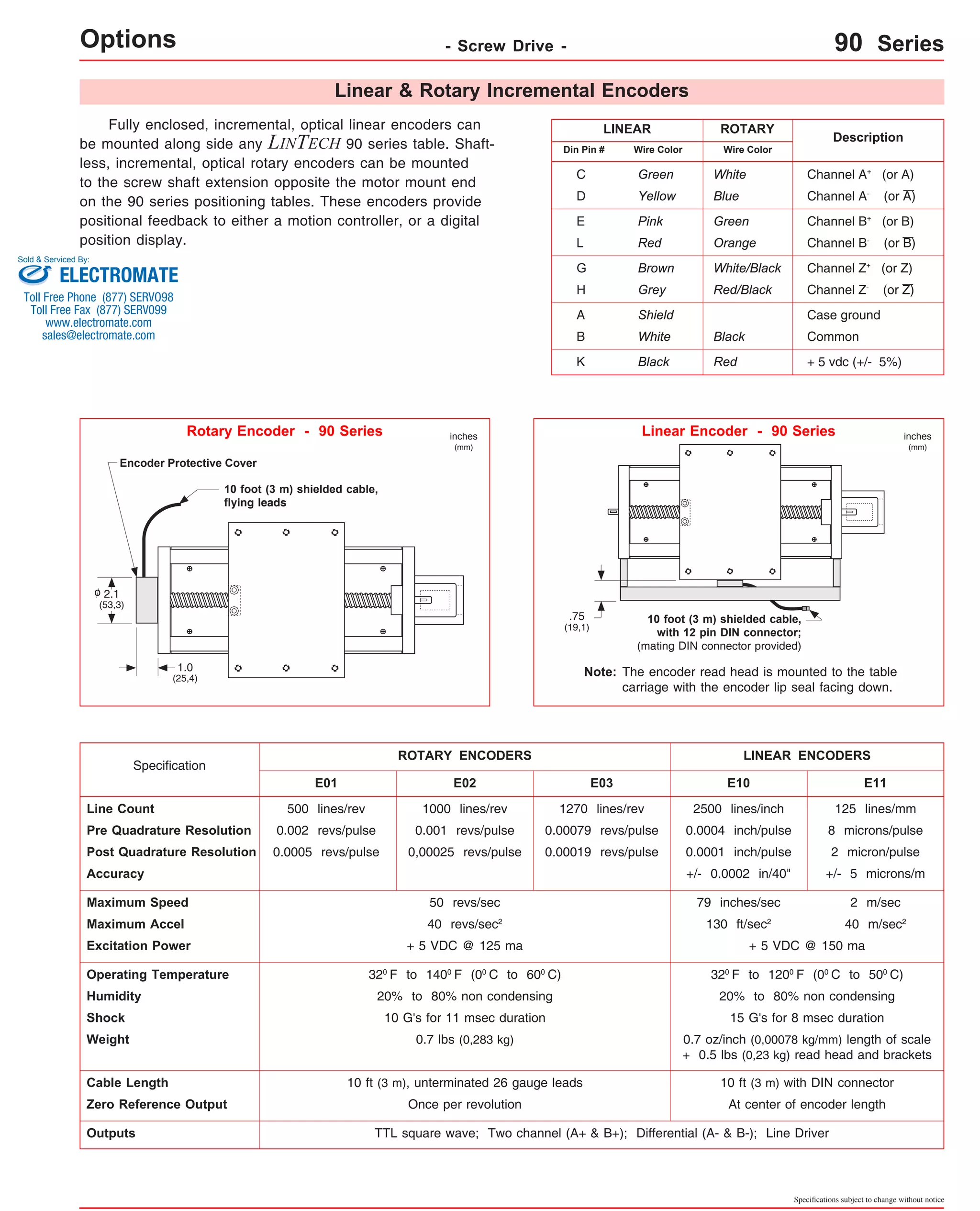
Downloaded 14 times

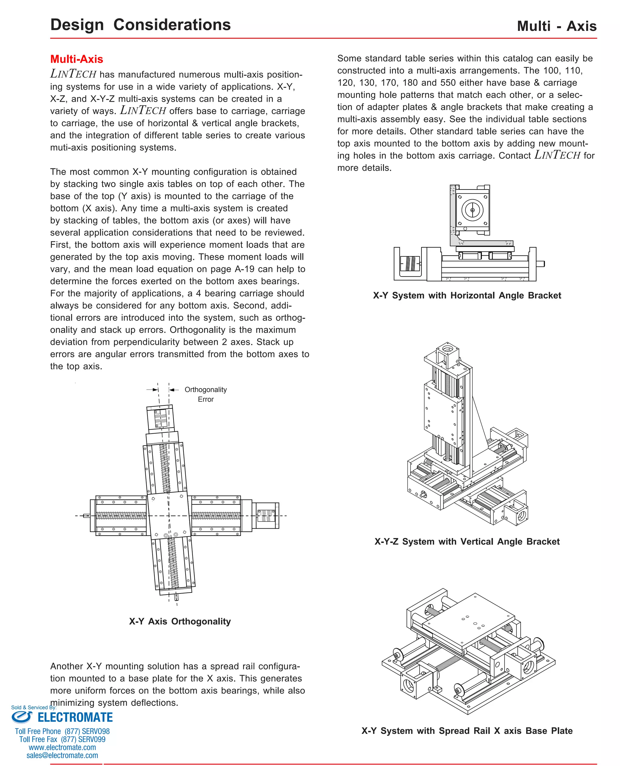


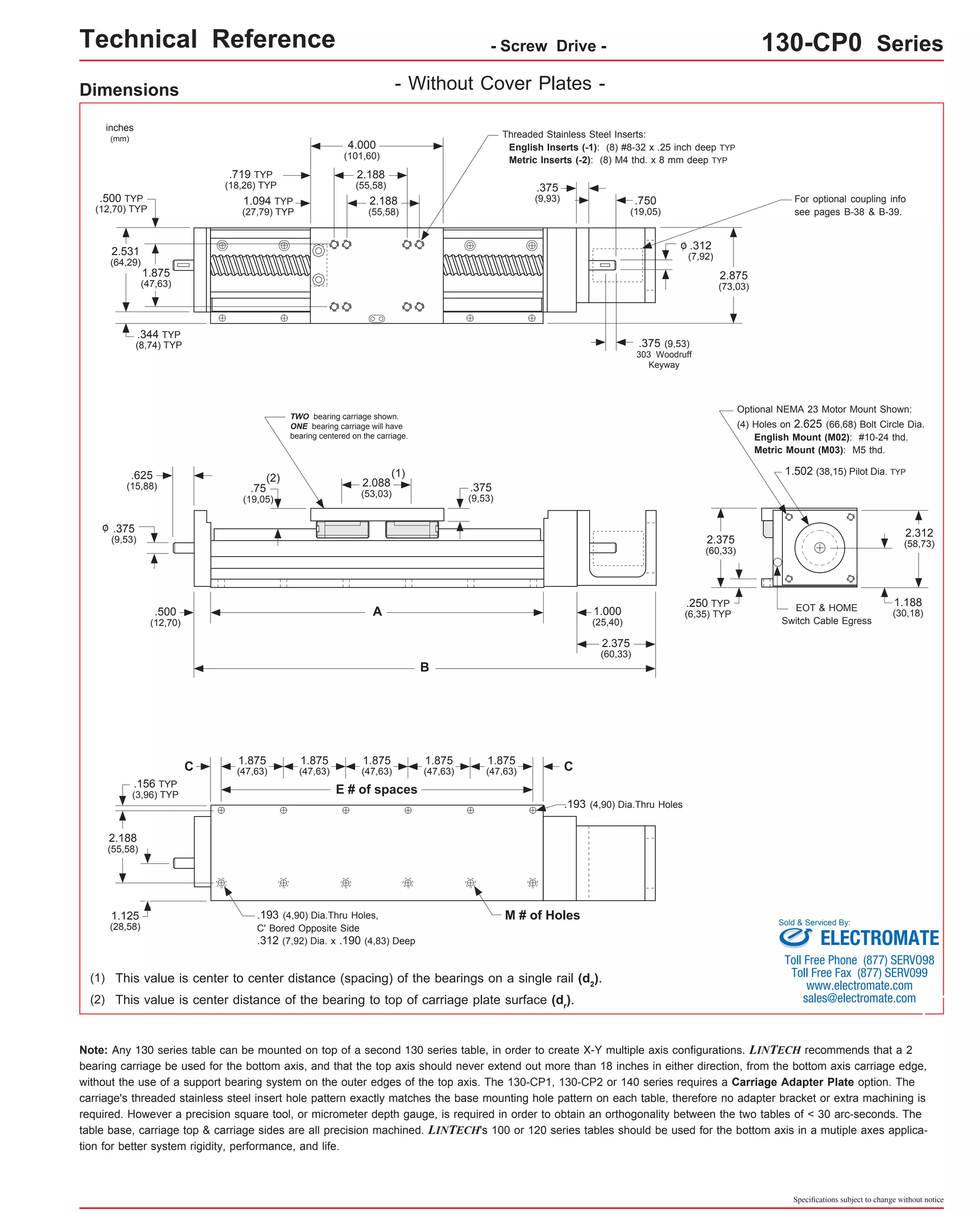
![Technical Reference - Screw Drive - 130-CP0 Series
- Without Cover Plates -
Mounting Dimensions
inches
(mm)
Dimensions & Specifications
Table Dimensions
inches
(mm)
Travel
Length
Screw
Length
inches
(mm)
9.25
(235)
Table
Weight
Model
Number lbs
(kg)
C
4.8
inches
(mm)
A
6.0
(152,4)
B
9.875
(250,8)
0.188
(4,8)
E M
13x402-CP0 3
8
(2,2)
11.875
(301,6)
1.188
(30,2) 8 11.25
13.875
(352,4)
0.313
(8,0) 12 13.25
15.875
(403,2)
1.313
(33,4) 12 15.25
19.875
(504,8)
1.438
(36,5) 16 19.25
23.875
(606,4)
1.563
(39,7) 20 23.25
27.875
(708,0)
1.688
(42,9) 24 27.25
31.875
(809,6)
1.813
(46,1) 28 31.25
37.875
(962,0)
1.063
(27,0) 36 37.25
43.875
(1114,4)
0.313
(8,0) 44 43.25
49.875
(1266,8)
1.438
(36,5) 48 49.25
55.875
(1419,2)
0.688
(17,5) 56 55.25
61.875
(1571,6)
1.813
(46,1) 60 61.25
67.875
(1724,0)
1.063
(27,0) 68 67.25
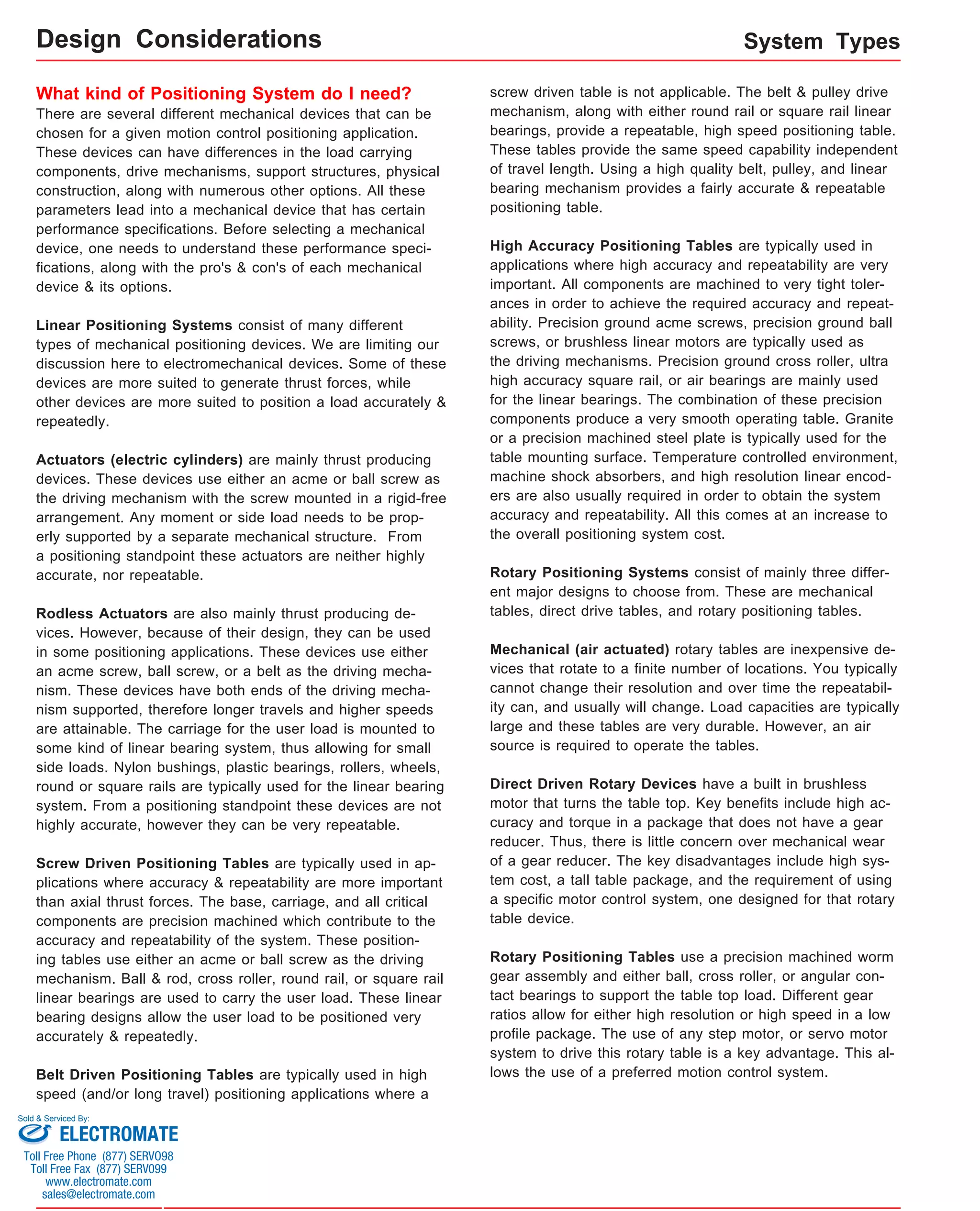
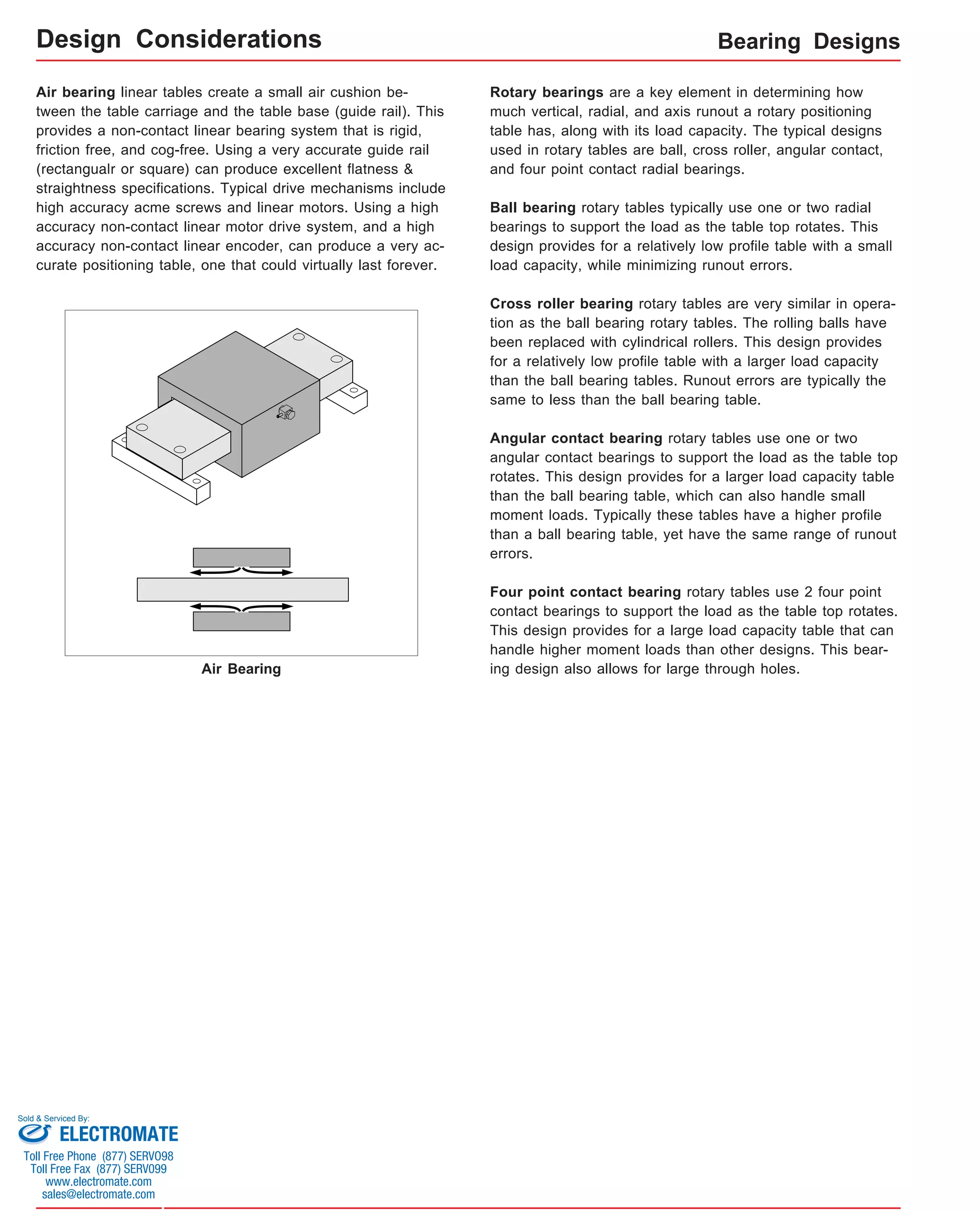
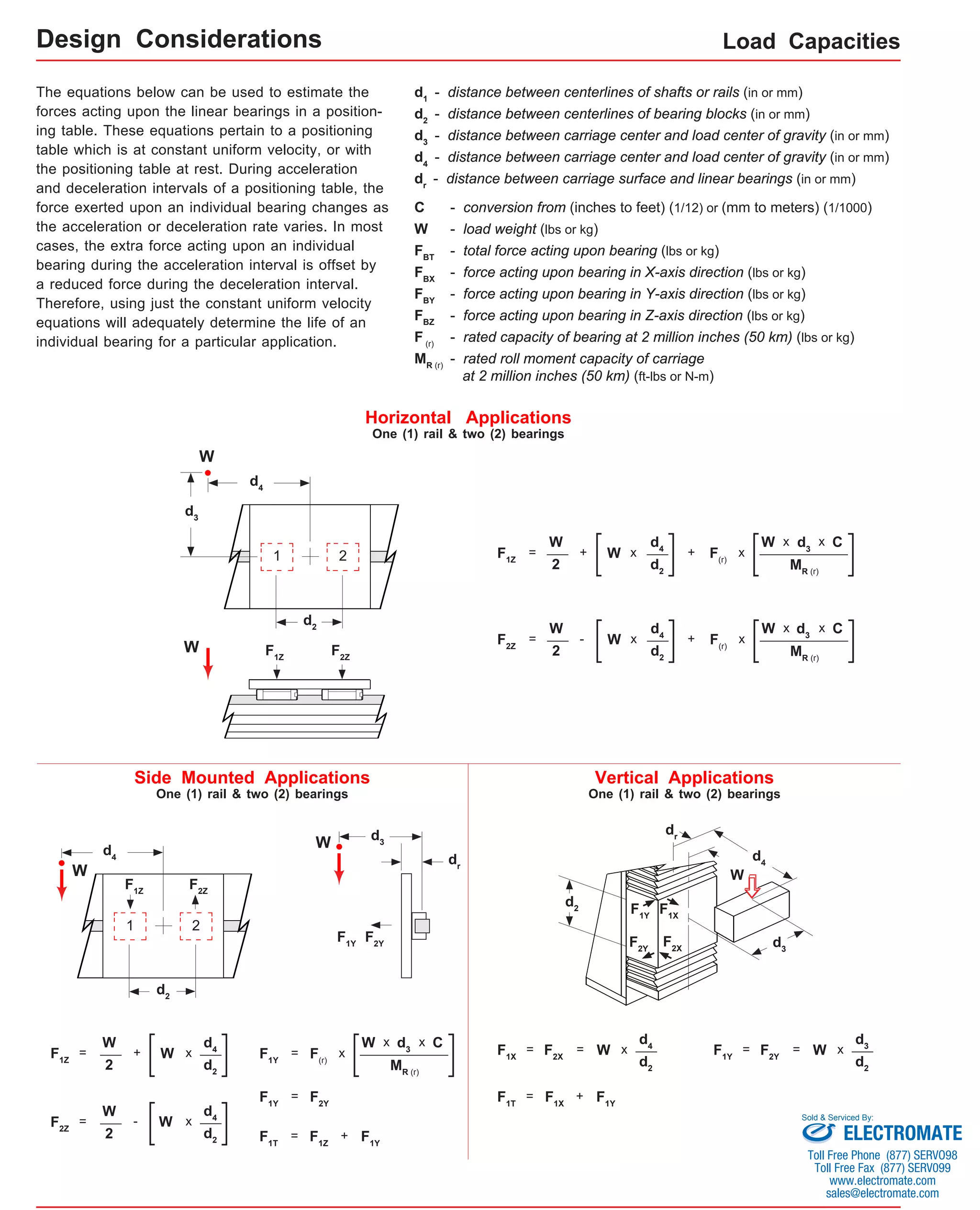
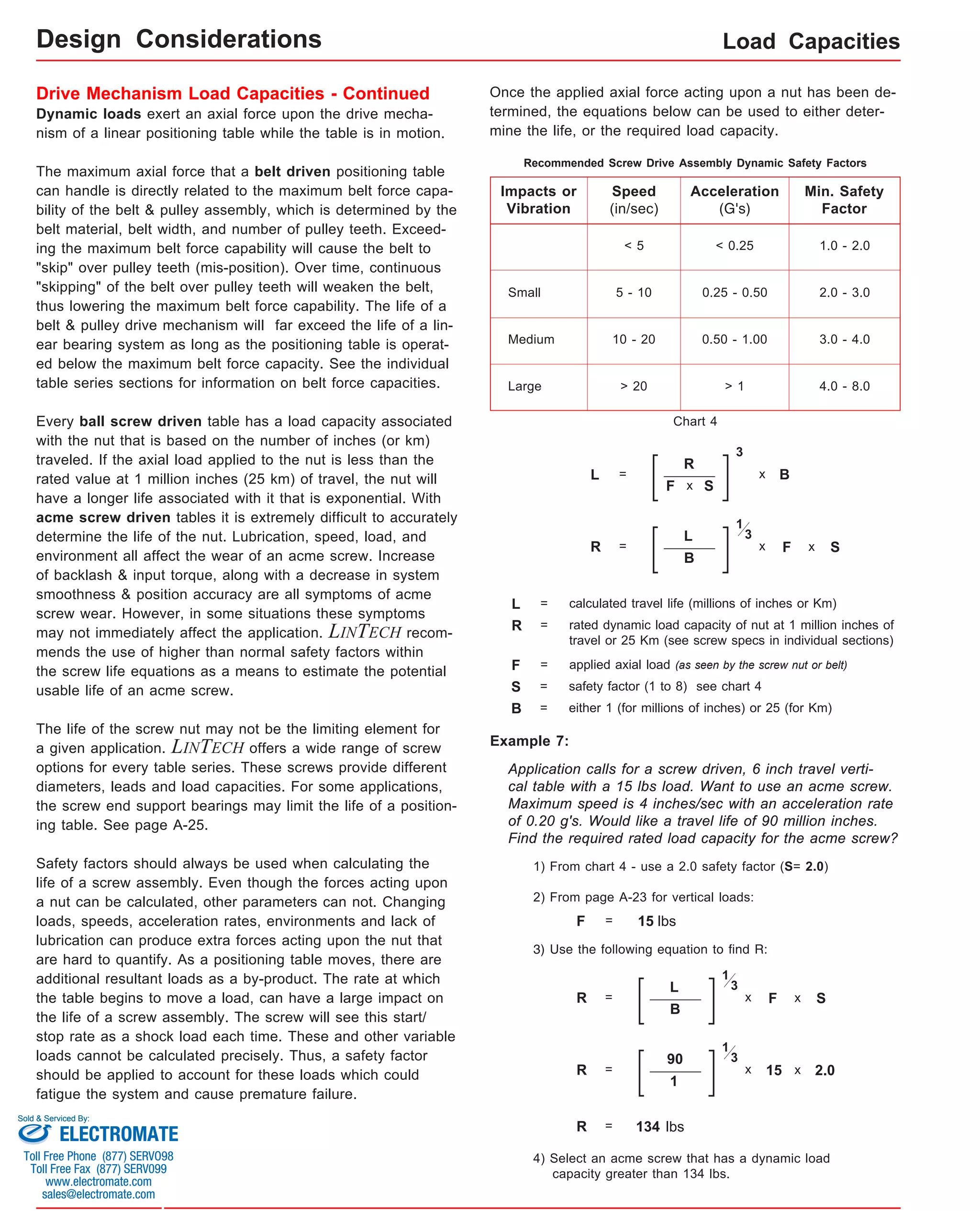
x = 1; Carriage has 1 bearing; Carriage weight = 1.1 lbs. (0,50 kg)
x = 2; Carriage has 2 bearings; Carriage weight = 1.2 lbs. (0,55 kg)
(1)
Footnotes:
(1) Weight shown is with a 0.625 inch (16 mm) diameter screw, a 1 bearing carriage [1.1 lbs (0,55 kg)], a NEMA 23 motor mount [0.34 lbs (0,16 kg)], and a C100
style [0.09 lbs (0,04 kg)] coupling. When using a 0.500 inch diameter screw subtract 0.022 lbs per inch (0,00039 kg per mm) of screw length for a given model
number. When using a 2 bearing carriage add 0.1 lbs (0,05 kg) to each value.
Sold & Serviced By:
Specifications subject to change without notice
5.3
13x404-CP0 8.0
(203,2)
3 (286)
(2,4) 2
(50)
4
(100)
5.8
13x406-CP0 6
10.0
(150)
(254,0)
5 (337) (2,6) 6.3
13x408-CP0 8
12.0
(200)
(304,8)
5 (387) (2,9) 7.3
13x412-CP0 12
16.0
(300)
(406,4)
7 (489) (3,3) 8.3
13x416-CP0 16
20.0
(405)
(508,0)
9 (591) (3,8) 9.3
13x420-CP0 20
24.0
(505)
(609,6)
11 (692) (4,2) 10.3
13x424-CP0 24
28.0
(605)
(711.2)
13 (794) (4,7) 11.8
13x430-CP0 30
34.0
(760)
(863,6)
17 (946) (5,4) 13.3
13x436-CP0 36
40.0
(910)
(1016,0)
21 (1099) (6,0) 14.8
13x442-CP0 42
46.0
(1060)
(1168,4)
23 (1251) (6,7) 16.3
13x448-CP0 48
52.0
(1215)
(1320,8)
27 (1403) (7,4) 17.8
13x454-CP0 54
58.0
(1370)
(1473,2)
29 (1556) (8,1) 19.3
13x460-CP0 60
64.0
(1520)
(1625,6)
33 (1708) (8,8) version: 01/2014
ELECTROMATE
Toll Free Phone (877) SERVO98
Toll Free Fax (877) SERV099
www.electromate.com
sales@electromate.com](https://image.slidesharecdn.com/lintechpositioningsystemscatalog-141018113223-conversion-gate01/75/Lintech-positioning-systems_catalog-61-2048.jpg)
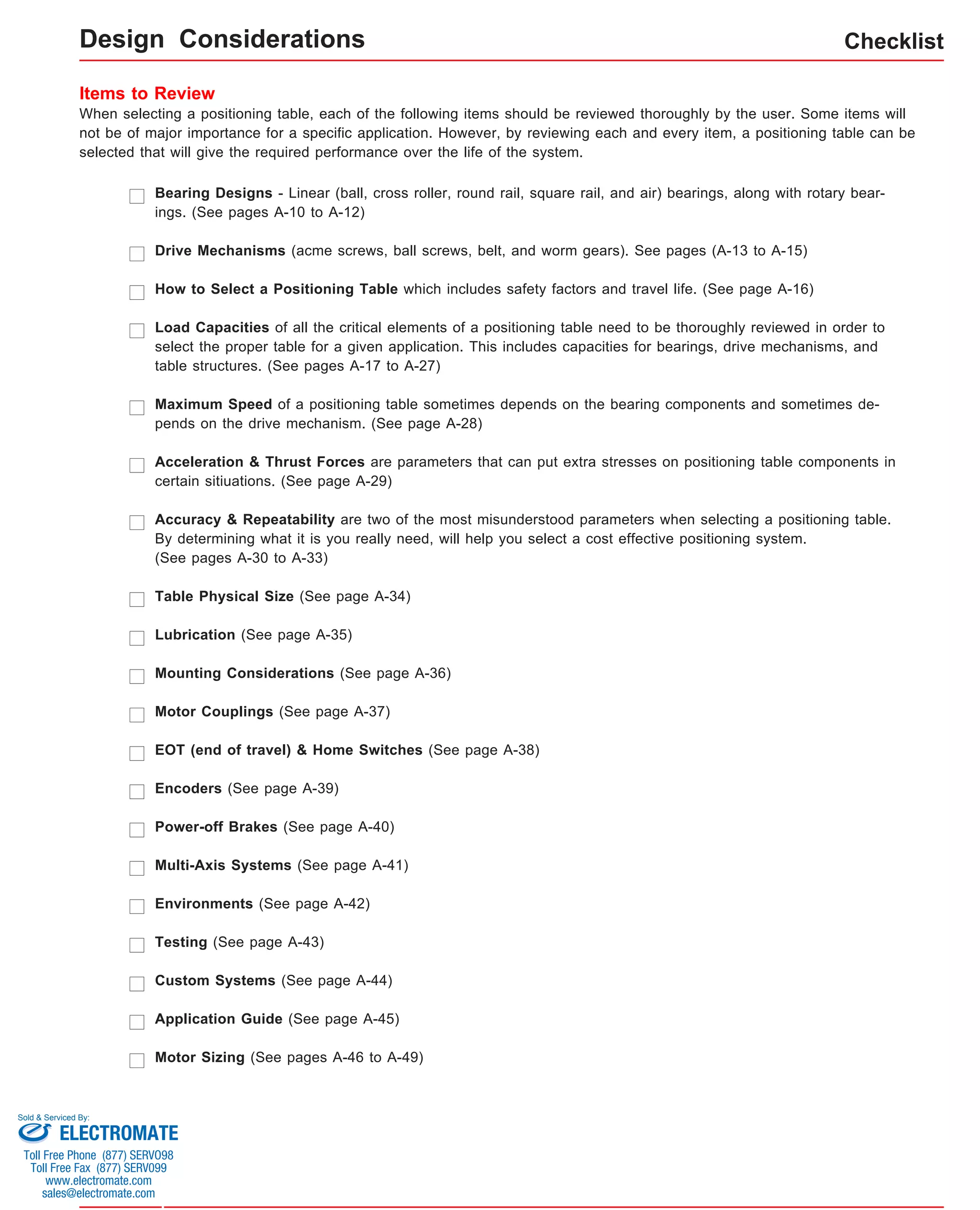
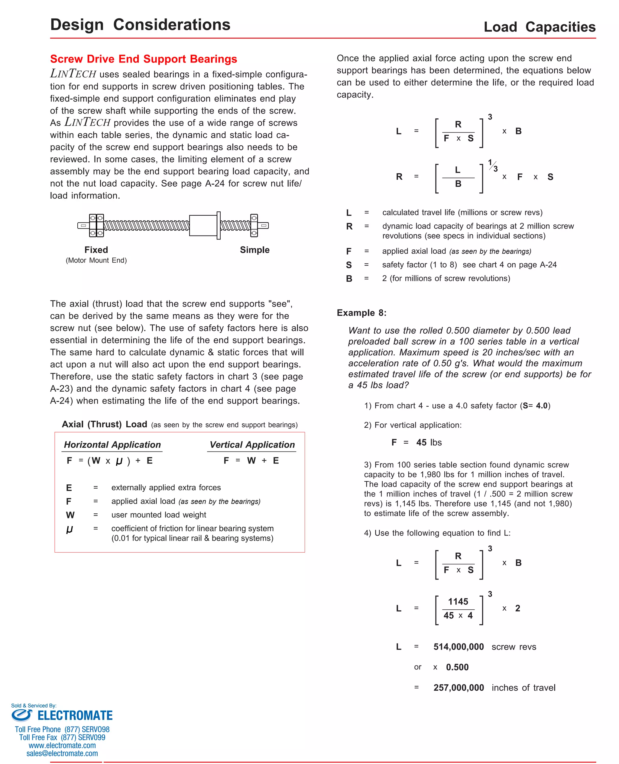
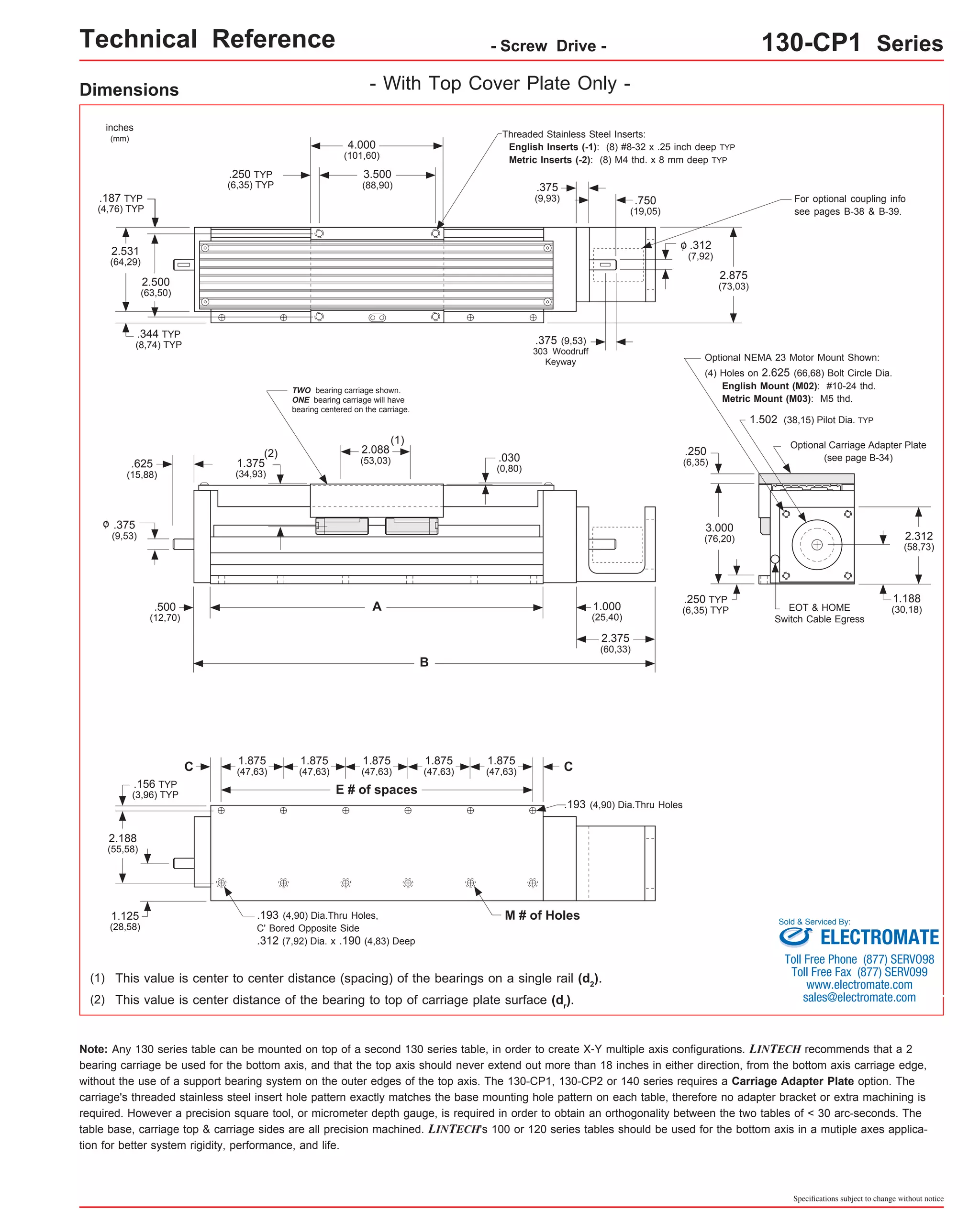
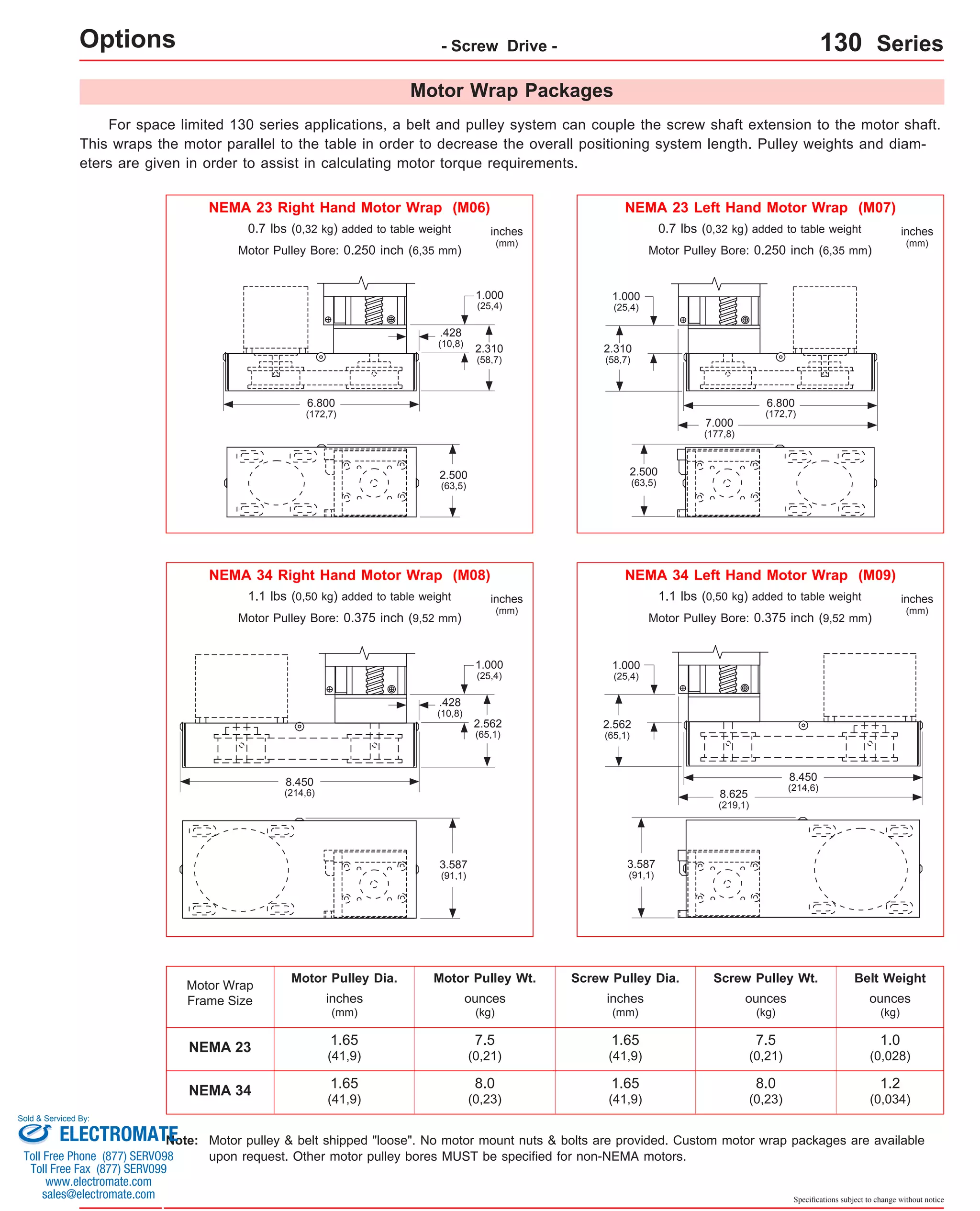
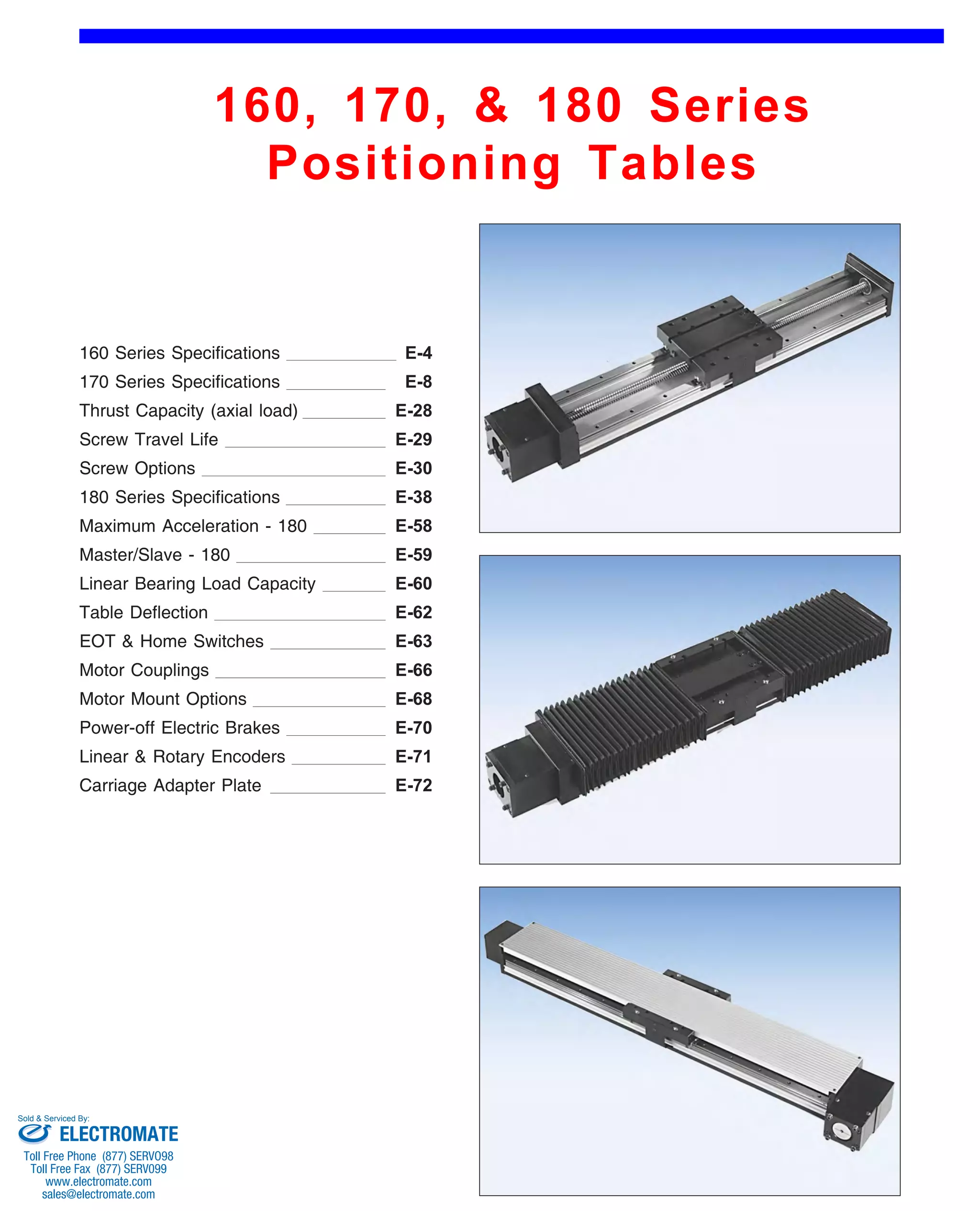
![Technical Reference - Screw Drive - 130-CP1 Series
Dimensions & Specifications
Travel
Length
Table Dimensions
Model
Number lbs
(kg)
inches
(mm)
C
inches
(mm)
Mounting Dimensions
5.5
inches
(mm)
A
6.0
(152,4)
B
9.875
(250,8)
0.188
(4,8)
E M
13x402-CP1 8
(2,5)
Screw
Length
inches
(mm)
9.25
(235)
Table
Weight
13x404-CP1 (2,8) 8.0
13x406-CP1 (3,1) 10.0
13x408-CP1 (3,4) 12.0
13x412-CP1 (4,0) 16.0
13x416-CP1 (4,5) 20.0
13x420-CP1 (5,1) 24.0
13x424-CP1 (5,7) 28.0
13x430-CP1 (6,6) 34.0
13x436-CP1 (7,5) 40.0
13x442-CP1 (8,4) 46.0
13x448-CP1 (9,3) 52.0
13x454-CP1 (10,1) 58.0
13x460-CP1 (11,0) 64.0
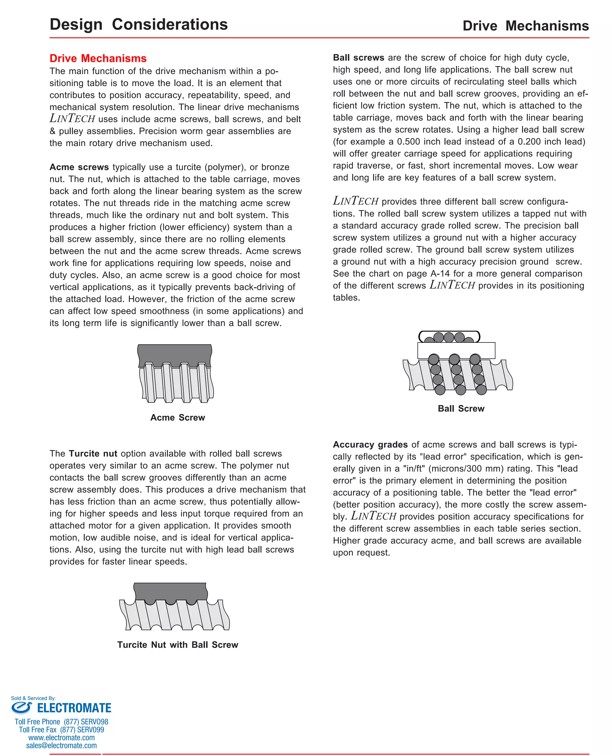
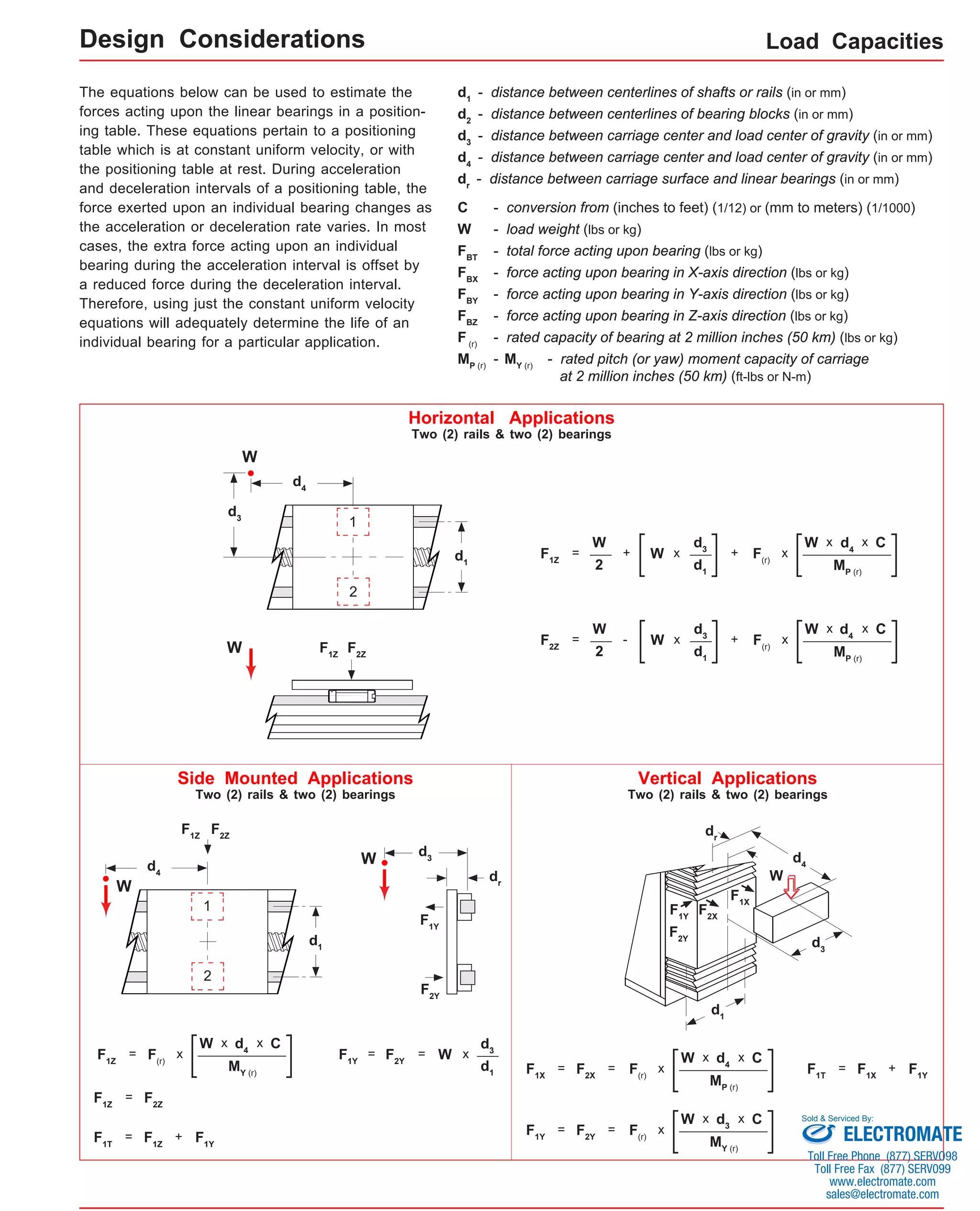
x = 1; Carriage has 1 bearing; Carriage weight = 1.4 lbs. (0,64 kg)
x = 2; Carriage has 2 bearings; Carriage weight = 1.5 lbs. (0,68 kg)
(1)
3
6.2
(203,2)
11.875
(301,6)
1.188
3 8 11.25
(30,2) (286)
2
(50)
4
(100)
6.8
(254,0)
13.875
(352,4)
0.313
(8,0) 12 13.25
5 (337) 6
(150)
7.4
(304,8)
15.875
(403,2)
1.313
(33,4) 12 15.25
5 (387) 8
(200)
8.8
(406,4)
19.875
(504,8)
1.438
(36,5) 16 19.25
7 (489) 12
(300)
10.0
(508,0)
23.875
(606,4)
1.563
(39,7) 20 23.25
9 (591) 16
(405)
11.3
(609,6)
27.875
(708,0)
1.688
(42,9) 24 27.25
11 (692) 20
(505)
12.6
(711.2)
31.875
(809,6)
1.813
(46,1) 28 31.25
13 (794) 24
(605)
14.6
(863,6)
37.875
(962,0)
1.063
(27,0) 36 37.25
17 (946) 30
(760)
16.5
(1016,0)
43.875
(1114,4)
0.313
(8,0) 44 43.25
21 (1099) 36
(910)
18.4
(1168,4)
49.875
(1266,8)
1.438
(36,5) 48 49.25
23 (1251) 42
(1060)
20.4
(1320,8)
55.875
(1419,2)
0.688
(17,5) 56 55.25
27 (1403) 48
(1215)
22.3
(1473,2)
61.875
(1571,6)
1.813
(46,1) 60 61.25
29 (1556) 54
(1370)
24.3
(1625,6)
67.875
(1724,0)
1.063
(27,0) 68 67.25
33 (1708) 60
(1520)
Sold & Serviced By:
Specifications subject to change without notice
- With Top Cover Plate Only -
Footnotes:
(1) Weight shown is with a 0.625 inch (16 mm) diameter screw, a 1 bearing carriage [1.1 lbs (0,55 kg)], a NEMA 23 motor mount [0.34 lbs (0,16 kg)], and a
C100 style [0.09 lbs (0,04 kg)] coupling. When using a 0.500 inch diameter screw subtract 0.022 lbs per inch (0,00039 kg per mm) of screw length for a
given model number. When using a 2 bearing carriage add 0.1 lbs (0,05 kg) to each value.
ELECTROMATE
Toll Free Phone (877) SERVO98
Toll Free Fax (877) SERV099
www.electromate.com
sales@electromate.com](https://image.slidesharecdn.com/lintechpositioningsystemscatalog-141018113223-conversion-gate01/75/Lintech-positioning-systems_catalog-63-2048.jpg)
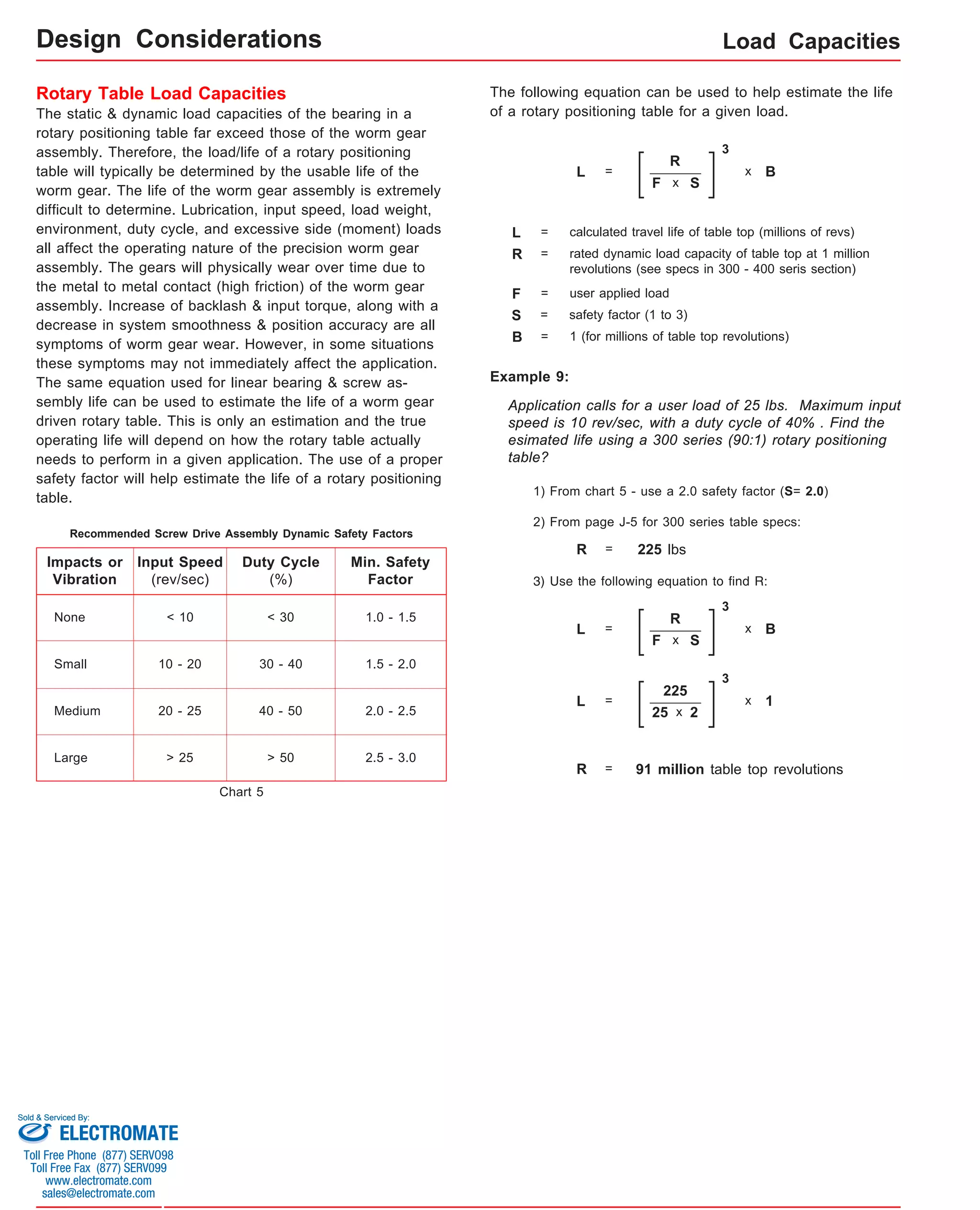
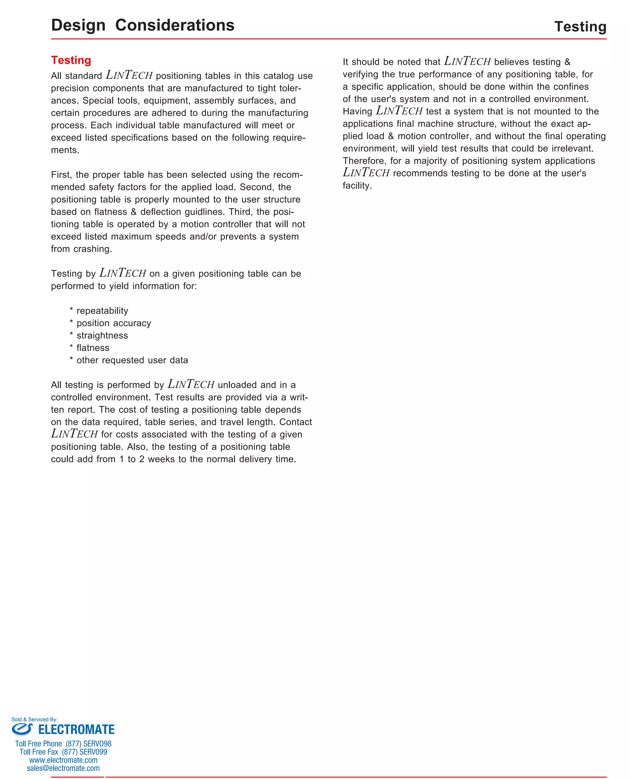
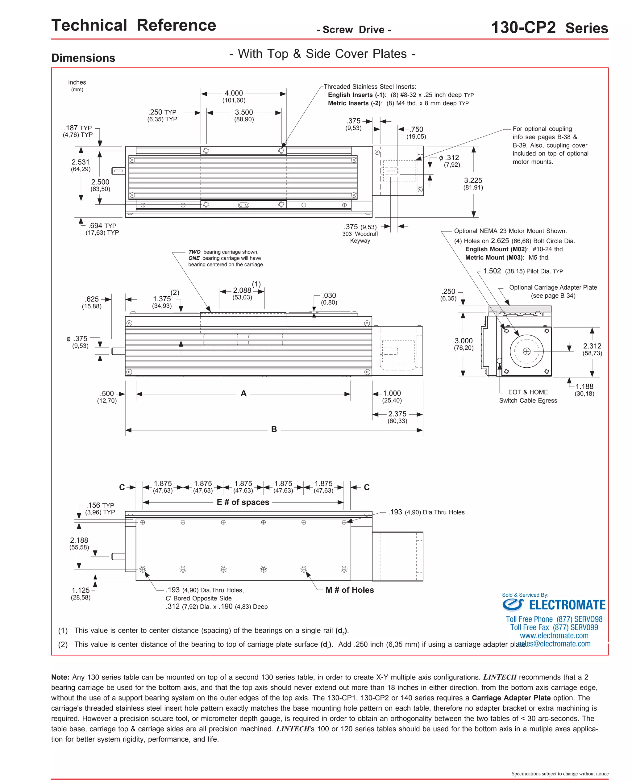
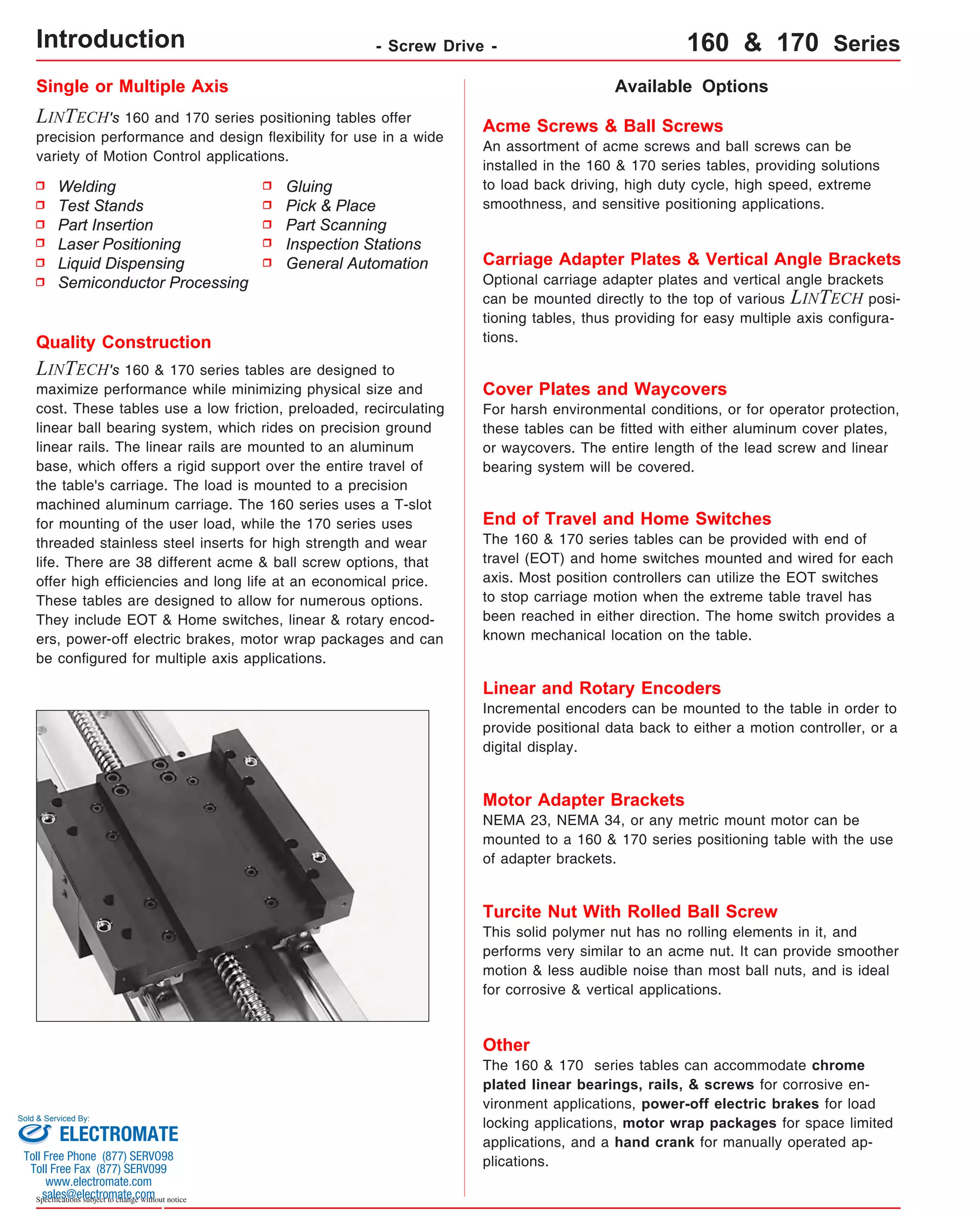
![Technical Reference - Screw Drive - 130-CP2 Series
Dimensions & Specifications
Travel
Length
Table Dimensions
Model
Number lbs
(kg)
5.7
(2,58)
6.4
(2,90)
7.0
(3,17)
7.6
(3,45)
9.1
(4,13)
10.4
(4,72)
11.7
(5,31)
13.1
(5,94)
15.1
(6,85)
17.1
(7,76)
19.1
(8,66)
21.2
(9,62)
23.2
(10,52)
25.3
(11,47)
inches
(mm)
C
inches
(mm)
Mounting Dimensions
13x402-CP2
inches
(mm)
A
6.0
(152,4)
B
9.875
(250,8)
0.188
(4,8)
E M
8
Screw
Length
inches
(mm)
9.25
(235)
Table
Weight
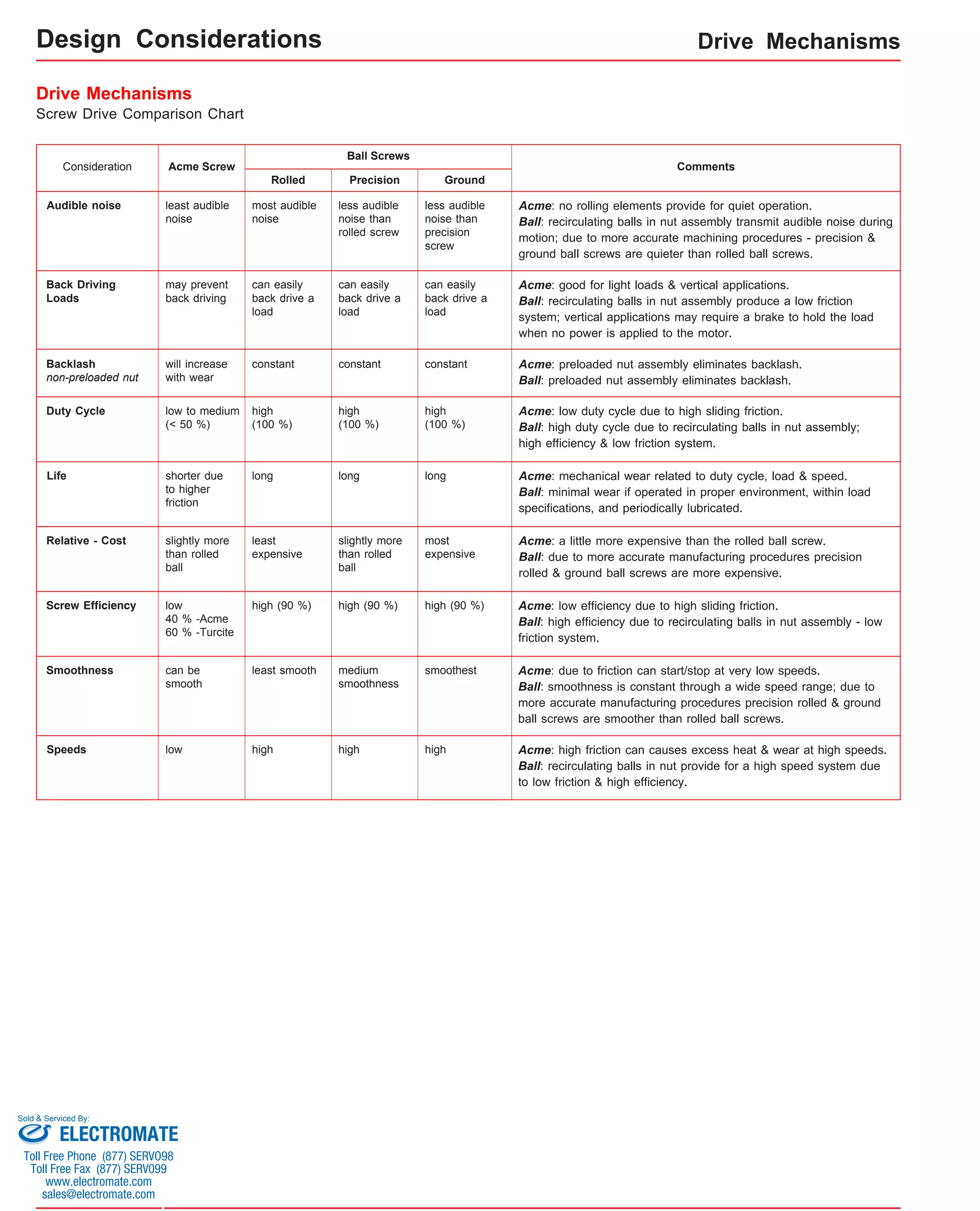
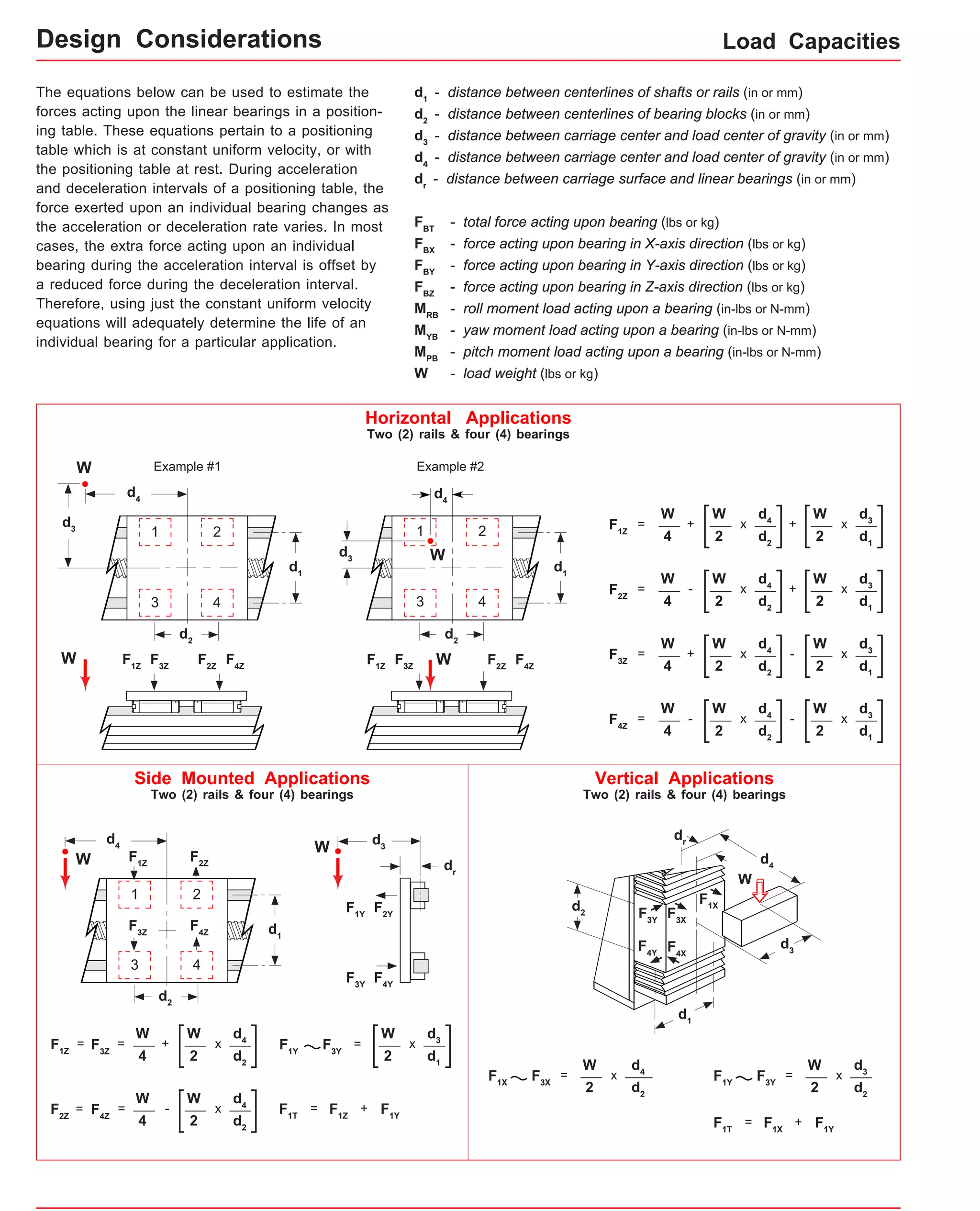
x = 1; Carriage has 1 bearing; Carriage weight = 1.4 lbs. (0,64 kg)
x = 2; Carriage has 2 bearings; Carriage weight = 1.5 lbs. (0,68 kg)
(1)
3
13x404-CP2 8.0
(203,2)
11.875
(301,6)
1.188
3 8 11.25
(30,2) (286)
2
(50)
4
(100)
13x406-CP2 10.0
(254,0)
13.875
(352,4)
0.313
(8,0) 12 13.25
5 (337) 6
(150)
13x408-CP2 12.0
(304,8)
15.875
(403,2)
1.313
(33,4) 12 15.25
5 (387) 8
(200)
13x412-CP2 16.0
(406,4)
19.875
(504,8)
1.438
(36,5) 16 19.25
7 (489) 12
(300)
13x416-CP2 20.0
(508,0)
23.875
(606,4)
1.563
(39,7) 20 23.25
9 (591) 16
(405)
13x420-CP2 24.0
(609,6)
27.875
(708,0)
1.688
(42,9) 24 27.25
11 (692) 20
(505)
13x424-CP2 28.0
(711.2)
31.875
(809,6)
1.813
(46,1) 28 31.25
13 (794) 24
(605)
13x430-CP2 34.0
(863,6)
37.875
(962,0)
1.063
(27,0) 36 37.25
17 (946) 30
(760)
13x436-CP2 40.0
(1016,0)
43.875
(1114,4)
0.313
(8,0) 44 43.25
21 (1099) 36
(910)
13x442-CP2 46.0
(1168,4)
49.875
(1266,8)
1.438
(36,5) 48 49.25
23 (1251) 42
(1060)
13x448-CP2 52.0
(1320,8)
55.875
(1419,2)
0.688
(17,5) 56 55.25
27 (1403) 48
(1215)
13x454-CP2 58.0
(1473,2)
61.875
(1571,6)
1.813
(46,1) 60 61.25
29 (1556) 54
(1370)
13x460-CP2 64.0
(1625,6)
67.875
(1724,0)
1.063
(27,0) 68 67.25
33 (1708) 60
(1520)
Sold & Serviced By:
Specifications subject to change without notice
- With Top & Side Cover Plates -
Footnotes:
(1) Weight shown is with a 0.625 inch (16 mm) diameter screw, a 1 bearing carriage [1.1 lbs (0,55 kg)], a NEMA 23 motor mount [0.34 lbs (0,16 kg)], and a
C100 style [0.09 lbs (0,04 kg)] coupling. When using a 0.500 inch diameter screw subtract 0.022 lbs per inch (0,00039 kg per mm) of screw length for a
given model number. When using a 2 bearing carriage add 0.1 lbs (0,05 kg) to each value.
ELECTROMATE
Toll Free Phone (877) SERVO98
Toll Free Fax (877) SERV099
www.electromate.com
sales@electromate.com](https://image.slidesharecdn.com/lintechpositioningsystemscatalog-141018113223-conversion-gate01/75/Lintech-positioning-systems_catalog-65-2048.jpg)


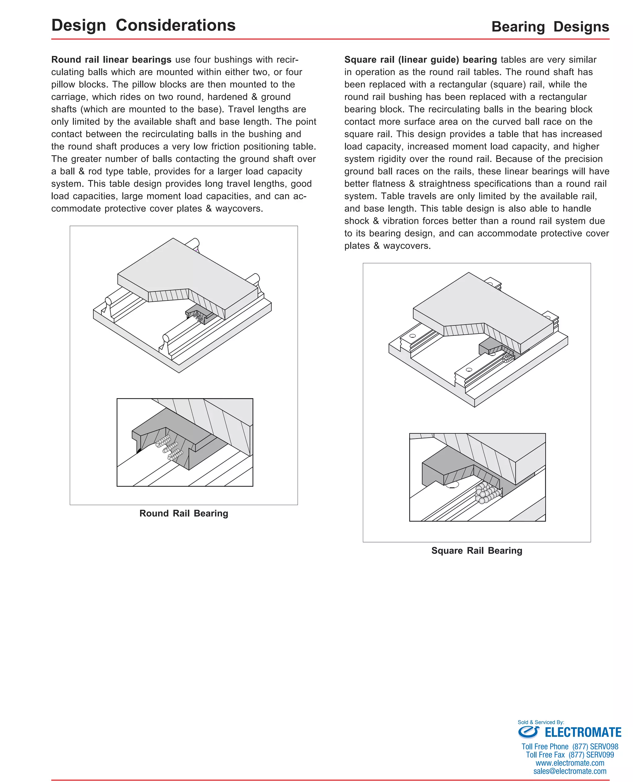
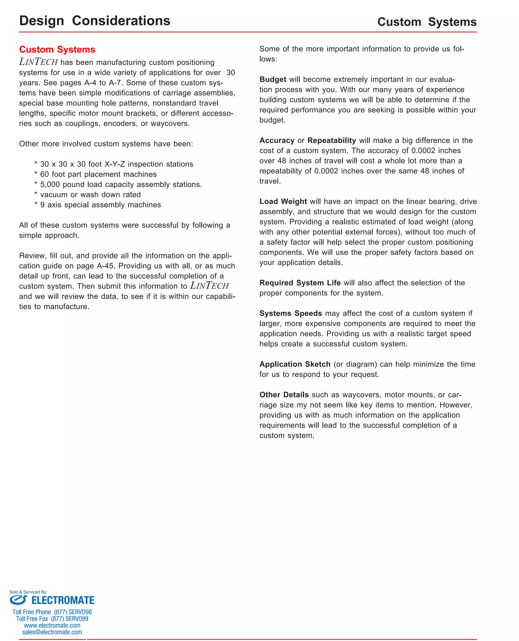
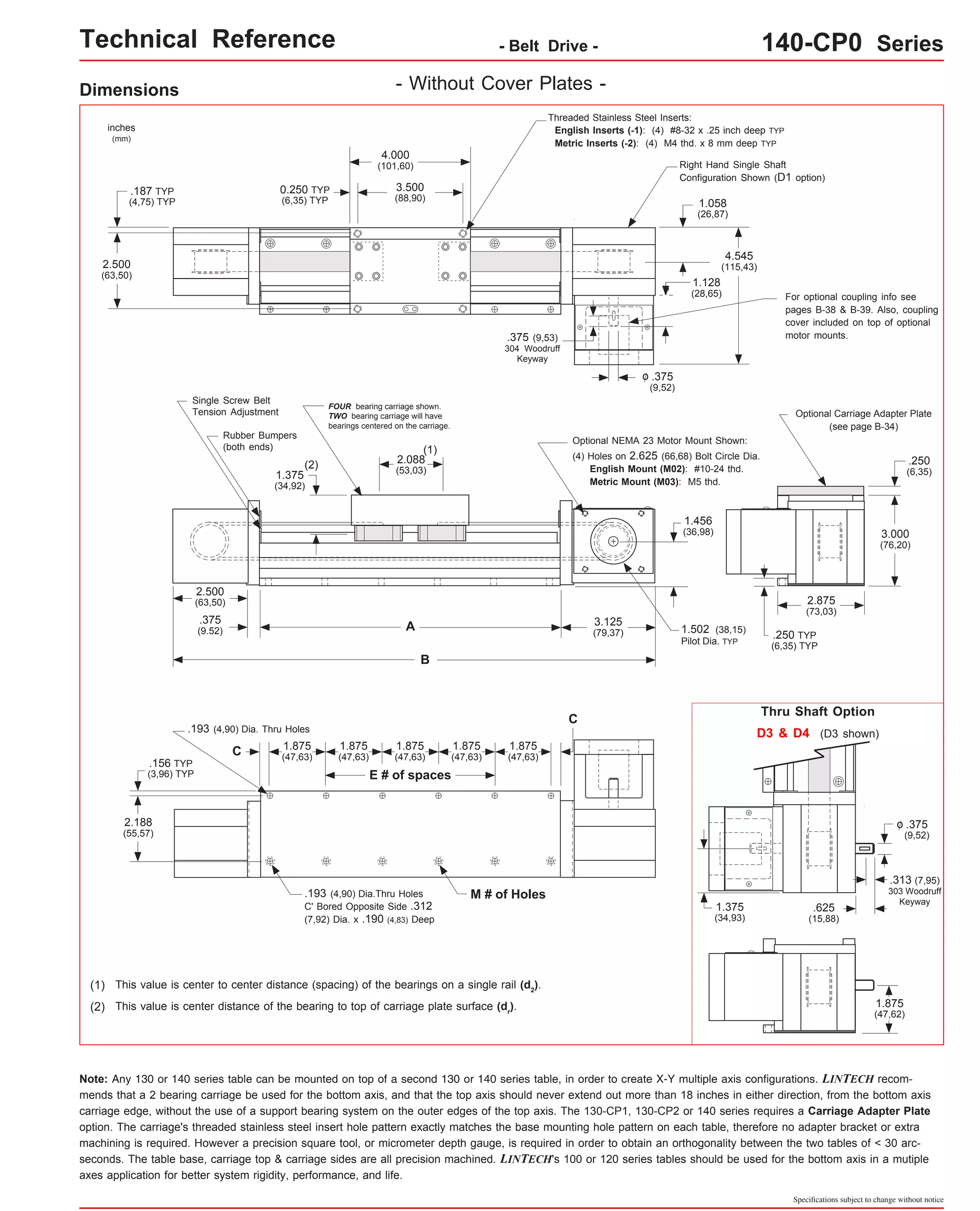
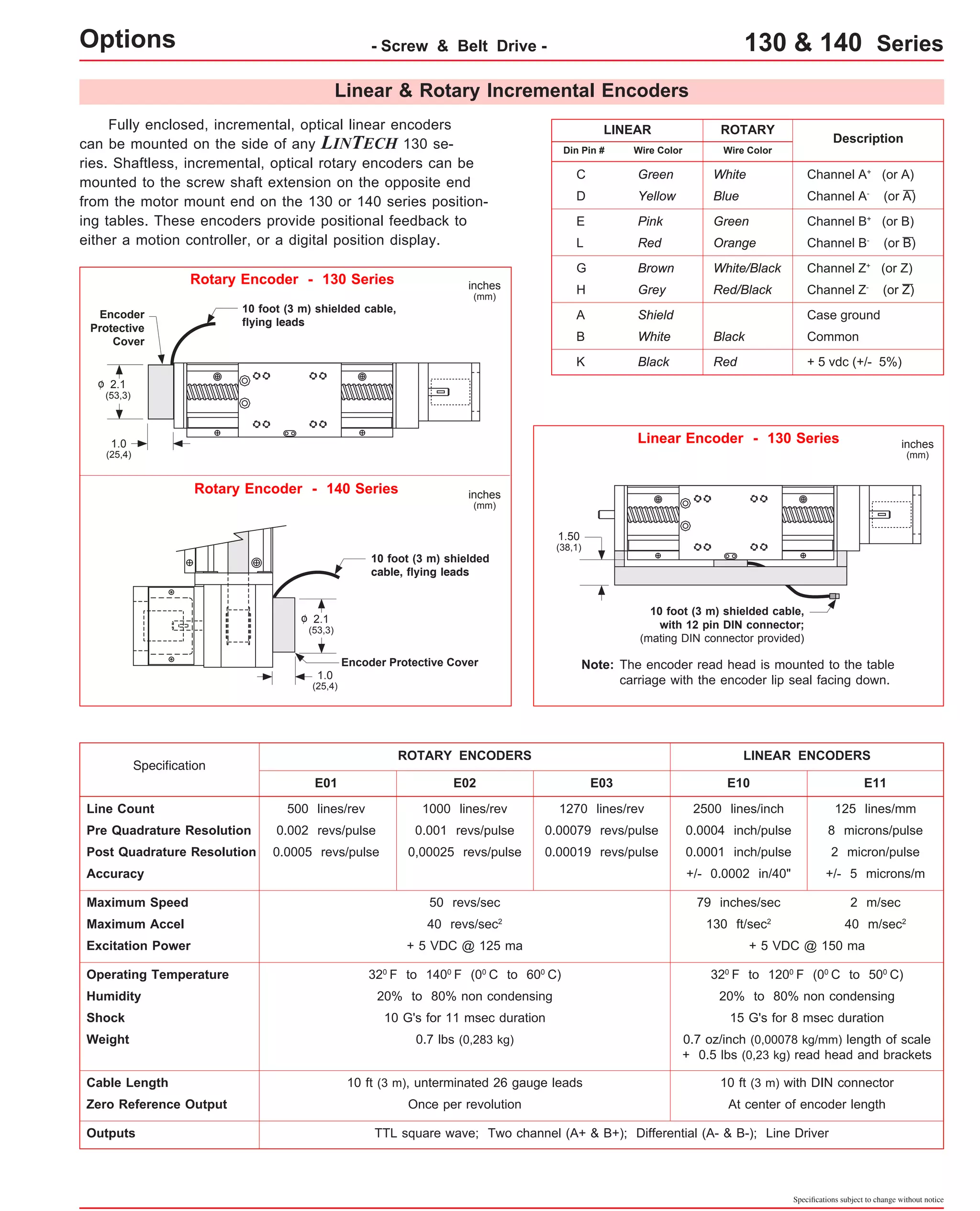
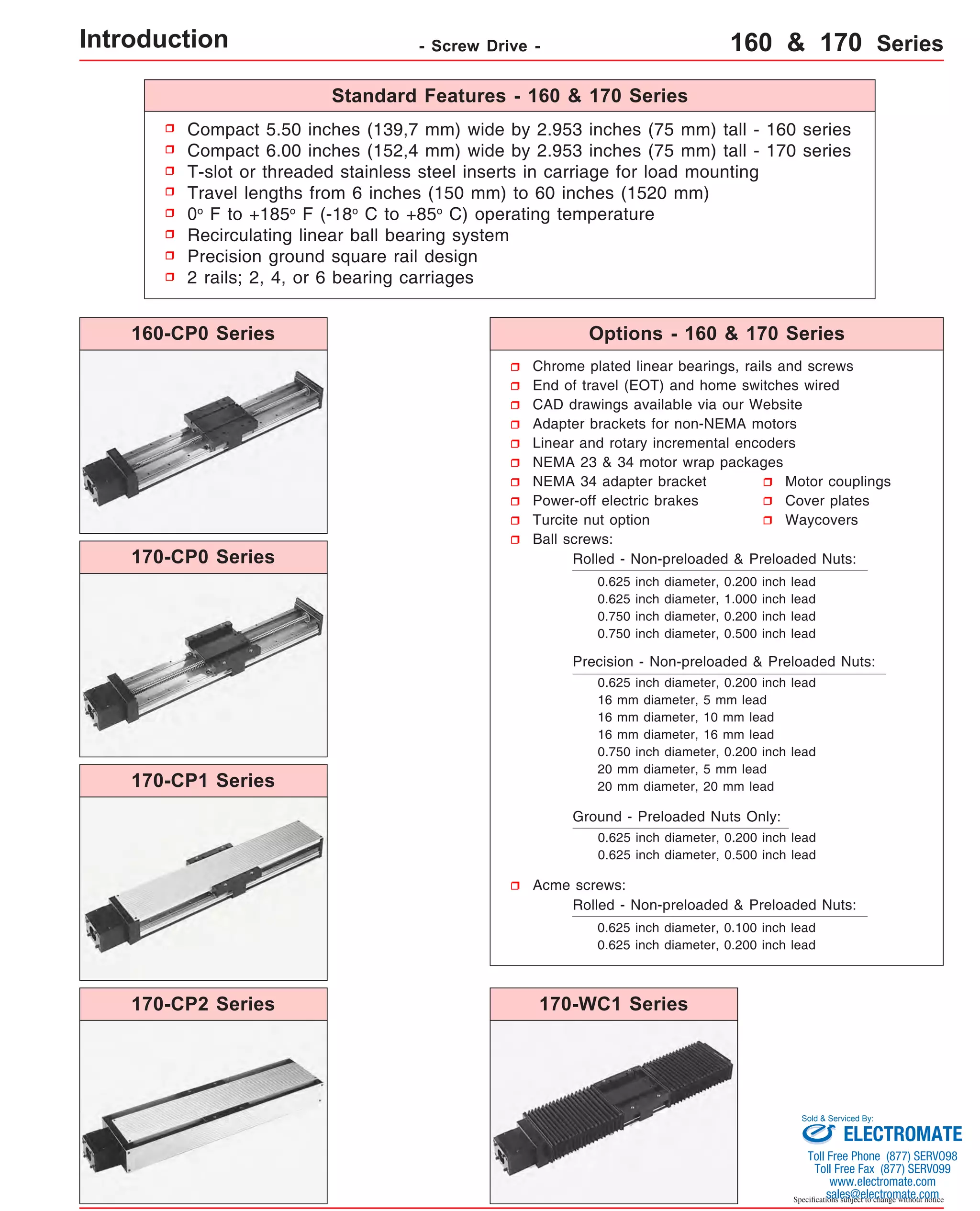
![Technical Reference - Belt Drive - 140-CP0 Series
Mounting Dimensions
inches
(mm)
Table Dimensions
inches
(mm)
Travel
Length
Table
Weight
Model
Number lbs
14x4004-CP0
14x4006-CP0
Footnotes:
(1)
- Without Cover Plates -
Belt
Weight
ounces
(gm)
1.3
(36,8)
B C
E M
inches
(mm)
A
4
8.0
14.0
1.188
(100)
(203,2)
(355,6)
(30,2) 3 8 6
10.0
16.0
0.313
(150)
(254,0)
(406,4)
(8,0) 5 12 8
12.0
18.0
1.313
(200)
(304,8)
(457,2)
(33,4) 5 12 12
16.0
22.0
1.438
(300)
(406,4)
(558,8)
(36,5) 7 16 16
20.0
26.0
1.563
(405)
(508,0)
(660,4)
(39,7) 9 20 20
24.0
30.0
1.688
(505)
(609,6)
(762,0)
(42,9) 11 24 24
28.0
34.0
1.813
(605)
(711.2)
(863,6)
(46,1) 13 28 30
34.0
40.0
1.063
(760)
(863,6)
(1016,0)
(27,0) 17 36 36
40.0
46.0
0.313
(910)
(1016,0)
(1168,4)
(8,0) 21 44 42
46.0
52.0
1.438
(1060)
(1168,4)
(1320,8)
(36,5) 23 48 48
52.0
58.0
0.688
(1215)
(1320,8)
(1473,2)
(17,5) 27 56 54
58.0
64.0
1.813
(1370)
(1473,2)
(1625,6)
(46,1) 29 60 60
64.0
70.0
1.063
(1520)
(1625,6)
(1778,0)
(27,0) 33 68 76.0
(1930,4)
82.0
(2082,8)
72
(1820)
88.0
(2235,2)
94.0
(2387,6)
84
(2130)
100.0
(2540,0)
106.0
(2692,4)
96
(2435)
112.0
(2844,8)
118.0
(2997,2)
108
(2740)
124.0
(3149,6)
130.0
(3302,0)
120
(3045)
39 80
45 92
51 104
57 116
63 128
0.500
(12,7)
0.875
(22,2)
0.313
(8,0)
0.688
(17,5)
1.063
(27,0)
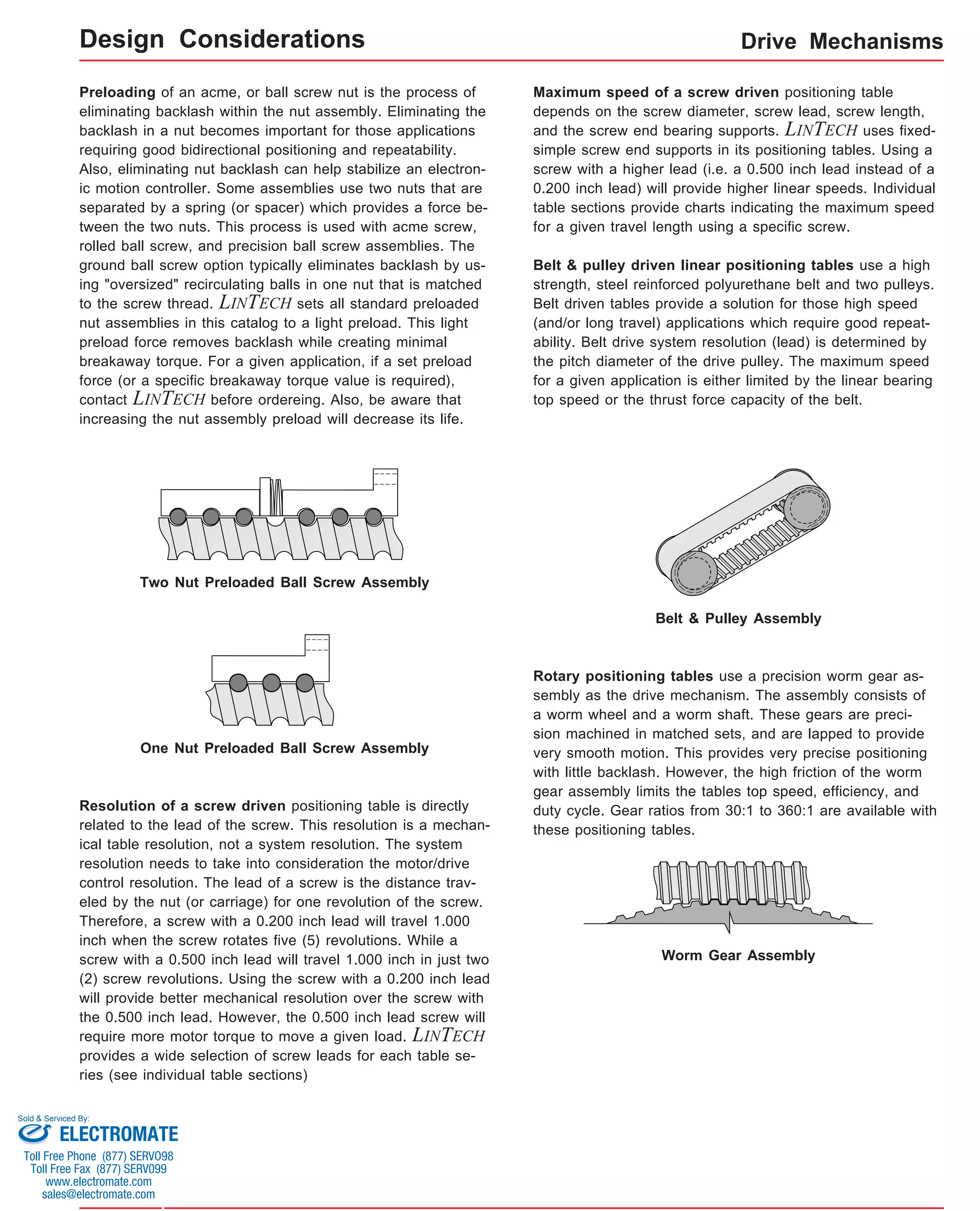
x = 1; Carriage has 1 bearing; Carriage weight = 1.4 lbs. (0,64 kg)
x = 2; Carriage has 2 bearings; Carriage weight = 1.5 lbs. (0,68 kg)
Specifications subject to change without notice
1.5
(42,5)
14x4008-CP0
1.7
(48,2)
Dimensions & Specifications
14x4012-CP0
2.1
(59,5)
14x4016-CP0
2.5
(70,9)
14x4020-CP0
2.9
(82,2)
14x4024-CP0
3.3
(93,6)
14x4030-CP0
3.9
(110,6)
14x4036-CP0
4.5
(127,6)
14x4042-CP0
5.1
(144,6)
14x4084-CP0
9.3
(263,7)
14x4096-CP0
10.5
(297,7)
14x4108-CP0
11.7
(331,7)
14x4120-CP0 12.9
(365,7)
14x4048-CP0
5.7
(161,6)
14x4054-CP0
6.3
(178,6)
14x4060-CP0
6.9
(195,6)
14x4072-CP0
8.1
(229,6)
(kg)
4.8
(2,2)
(1)
5.3
(2,4)
5.8
(2,6)
6.3
(2,9)
7.3
(3,3)
8.3
(3,8)
9.3
(4,2)
10.3
(4,7)
11.8
(5,4)
13.3
(6,0)
14.8
(6,7)
16.3
(7,4)
17.8
(8,1)
20.8
(9,4)
23.8
(10,8)
26.8
(12,2)
29.8
(13,5)
32.8
(14,9)
Sold & Serviced By:
Toll Free Phone (877) SERVO98
Toll Free Fax (877) SERV099
www.electromate.com
sales@electromate.com
Weight shown is with a 1 bearing carriage [1.4 lbs (0,64 kg)], a NEMA 23 motor mount [0.34 lbs (0,16 kg)], and a H100 style [0.08 lbs (0,04 kg)] coupling.
When using a 2 bearing carriage add 0.1 lbs (0,04 kg) to each value.
ELECTROMATE
version: 01/2014](https://image.slidesharecdn.com/lintechpositioningsystemscatalog-141018113223-conversion-gate01/75/Lintech-positioning-systems_catalog-79-2048.jpg)
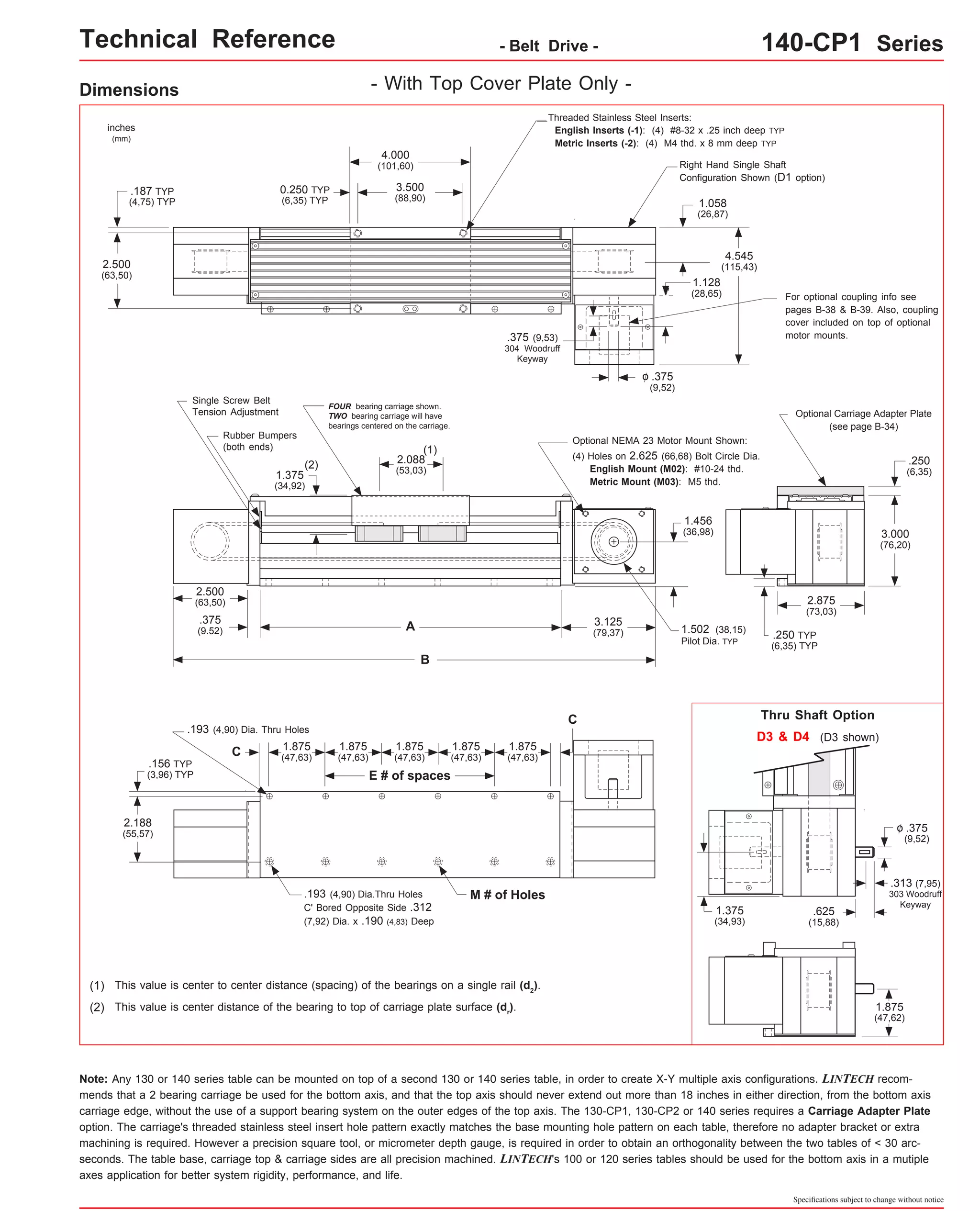
![Technical Reference - Belt Drive - 140-CP1 Series
Dimensions & Specifications
Travel
Length
Table Dimensions
Model
Number lbs
1.188
(30,2) 3 8 4
(100)
14x4006-CP1 1.5
1.438
(36,5) 23 48 42
(1060)
0.688
(17,5) 27 56 48
(1215)
1.813
(46,1) 29 60 54
(1370)
1.063
(27,0) 33 68 60
(1520)
Sold & Serviced By:
Specifications subject to change without notice
- With Top Cover Plate Only -
14x4004-CP1
Belt
Weight
ounces
(gm)
1.3
(36,8)
0.313
(8,0) 5 12 6
(150)
1.313
(33,4) 5 12 8
(200)
1.438
(36,5) 7 16 12
(300)
1.563
(39,7) 9 20 16
(405)
1.688
(42,9) 11 24 20
(505)
1.813
(46,1) 13 28 24
(605)
1.063
(27,0) 17 36 30
(760)
0.313
(8,0) 21 44 36
(910)
x = 1; Carriage has 1 bearing; Carriage weight = 1.4 lbs. (0,64 kg)
x = 2; Carriage has 2 bearings; Carriage weight = 1.5 lbs. (0,68 kg)
(42,5)
14x4008-CP1 1.7
(48,2)
14x4012-CP1 2.1
(59,5)
14x4016-CP1 2.5
(70,9)
14x4020-CP1 2.9
(82,2)
14x4024-CP1 3.3
(93,6)
14x4030-CP1 3.9
(110,6)
14x4036-CP1 4.5
(127,6)
14x4042-CP1 5.1
(144,6)
14x4048-CP1 5.7
(161,6)
14x4054-CP1 6.3
(178,6)
14x4060-CP1 6.9
(195,6)
(kg)
inches
(mm)
C
inches
(mm)
Mounting Dimensions
4.8
(2,2)
inches
(mm)
A
B E M
Table
Weight
(1)
5.3
(2,4)
8.0
(203,2)
14.0
(355,6)
5.8
(2,6)
10.0
(254,0)
16.0
(406,4)
6.3
(2,9)
12.0
(304,8)
18.0
(457,2)
7.3
(3,3)
16.0
(406,4)
22.0
(558,8)
8.3
(3,8)
20.0
(508,0)
26.0
(660,4)
9.3
(4,2)
24.0
(609,6)
30.0
(762,0)
10.3
(4,7)
28.0
(711.2)
34.0
(863,6)
11.8
(5,4)
34.0
(863,6)
40.0
(1016,0)
13.3
(6,0)
40.0
(1016,0)
46.0
(1168,4)
14.8
(6,7)
46.0
(1168,4)
52.0
(1320,8)
16.3
(7,4)
52.0
(1320,8)
58.0
(1473,2)
17.8
(8,1)
58.0
(1473,2)
64.0
(1625,6)
64.0
(1625,6)
70.0
(1778,0)
Footnotes:
(1) Weight shown is with a 1 bearing carriage [1.4 lbs (0,64 kg)], a NEMA 23 motor mount [0.34 lbs (0,16 kg)], and a H100 style [0.08 lbs (0,04 kg)] coupling.
When using a 2 bearing carriage add 0.1 lbs (0,04 kg) to each value.
ELECTROMATE
Toll Free Phone (877) SERVO98
Toll Free Fax (877) SERV099
www.electromate.com
sales@electromate.com](https://image.slidesharecdn.com/lintechpositioningsystemscatalog-141018113223-conversion-gate01/75/Lintech-positioning-systems_catalog-81-2048.jpg)
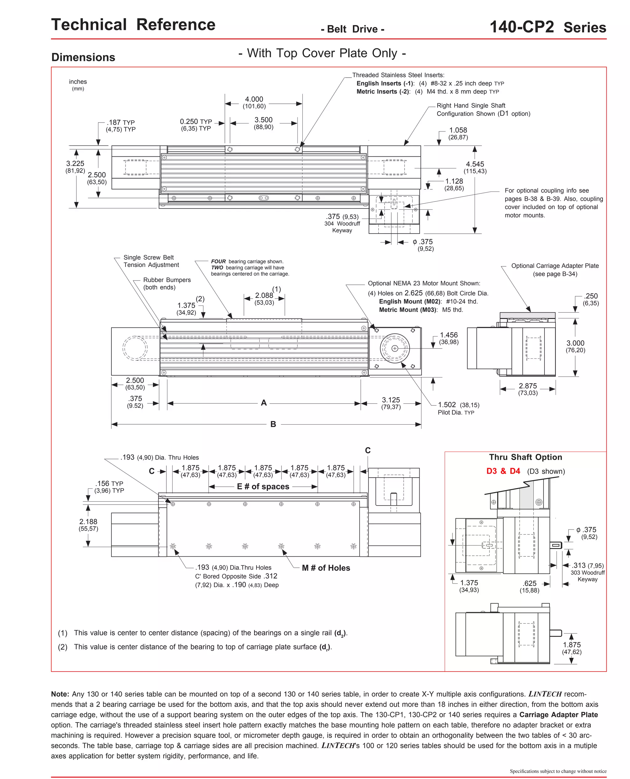
![Technical Reference - Belt Drive - 140-CP2 Series
Dimensions & Specifications - With Top Cover Plate Only -
Travel
Length
Table Dimensions
Model
Number lbs
14x4004-CP2
1.188
(30,2) 3 8 4
(100)
14x4006-CP2 1.5
1.438
(36,5) 23 48 42
(1060)
0.688
(17,5) 27 56 48
(1215)
1.813
(46,1) 29 60 54
(1370)
1.063
(27,0) 33 68 60
(1520)
Sold & Serviced By:
Specifications subject to change without notice
Belt
Weight
ounces
(gm)
1.3
(36,8)
0.313
(8,0) 5 12 6
(150)
1.313
(33,4) 5 12 8
(200)
1.438
(36,5) 7 16 12
(300)
1.563
(39,7) 9 20 16
(405)
1.688
(42,9) 11 24 20
(505)
1.813
(46,1) 13 28 24
(605)
1.063
(27,0) 17 36 30
(760)
0.313
(8,0) 21 44 36
(910)
x = 1; Carriage has 1 bearing; Carriage weight = 1.4 lbs. (0,64 kg)
x = 2; Carriage has 2 bearings; Carriage weight = 1.5 lbs. (0,68 kg)
(42,5)
14x4008-CP2 1.7
(48,2)
14x4012-CP2 2.1
(59,5)
14x4016-CP2 2.5
(70,9)
14x4020-CP2 2.9
(82,2)
14x4024-CP2 3.3
(93,6)
14x4030-CP2 3.9
(110,6)
14x4036-CP2 4.5
(127,6)
14x4042-CP2 5.1
(144,6)
14x4048-CP2 5.7
(161,6)
14x4054-CP2 6.3
(178,6)
14x4060-CP2 6.9
(195,6)
(kg)
inches
(mm)
C
inches
(mm)
Mounting Dimensions
5.0
(2,3)
inches
(mm)
A
B E M
Table
Weight
(1)
5.5
(2,5)
8.0
(203,2)
14.0
(355,6)
6.0
(2,7)
10.0
(254,0)
16.0
(406,4)
6.6
(3,0)
12.0
(304,8)
18.0
(457,2)
7.7
(3,5)
16.0
(406,4)
22.0
(558,8)
8.7
(3,9)
20.0
(508,0)
26.0
(660,4)
9.8
(4,5)
24.0
(609,6)
30.0
(762,0)
10.9
(5,0)
28.0
(711.2)
34.0
(863,6)
12.5
(5,7)
34.0
(863,6)
40.0
(1016,0)
14.0
(6,4)
40.0
(1016,0)
46.0
(1168,4)
15.6
(7,1)
46.0
(1168,4)
52.0
(1320,8)
17.2
(7,8)
52.0
(1320,8)
58.0
(1473,2)
18.8
(8,5)
58.0
(1473,2)
64.0
(1625,6)
64.0
(1625,6)
70.0
(1778,0)
Footnotes:
(1) Weight shown is with a 1 bearing carriage [1.4 lbs (0,64 kg)], a NEMA 23 motor mount [0.34 lbs (0,16 kg)], and a H100 style [0.08 lbs (0,04 kg)] coupling.
When using a 2 bearing carriage add 0.1 lbs (0,04 kg) to each value.
ELECTROMATE
Toll Free Phone (877) SERVO98
Toll Free Fax (877) SERV099
www.electromate.com
sales@electromate.com](https://image.slidesharecdn.com/lintechpositioningsystemscatalog-141018113223-conversion-gate01/75/Lintech-positioning-systems_catalog-83-2048.jpg)

![Technical Reference - Belt Drive - 140 Series
2.809
(71,35)
Master/Slave 140 Series Configuration
For some X-Y belt drive applications, the
master/slave configuration shown to the right
may be required. This system provides two
bottom (X) axes spread apart a set distance,
yet driven by one motor. The spreading of the
two bottom axes minimizes the deflection on
the Y axis, reduces the moment loading on the
X axes carriages, increases the system rigidity,
and prevents twisting of the Y axis as it acceler-ates
to a set speed. LINTECH can provide the
shaft supports, the cross shaft, the couplings,
and the 140 series belt drive table without a
motor mount bracket. The shaft supports are
required as the couplings DO NOT provide ad-equate
support of the shaft by themselves. Also,
the shaft supports prevent the cross shaft from
"whipping" at long lengths and high speeds.
The chart below lists the maximum carriage
speed available with a given distance between
shaft supports. A minimum of two shaft supports
is always required. More than two can be used
to increase the speed of a longer spread sys-tem.
The equations below show the relationship
between the # of shaft supports, the spread be-tween
the two bottom axes (B), and the distance
between individual shaft supports (A).
Max. Ref.
A
C191 coupling C191 coupling
(see chart)
Shaft Supports (44192)
B
Shaft Supports (44192)
C' Bore for 1/4-20 (M6)
socket head cap screw
Steel Cross Shaft: 0.500 inch (12,7 mm) diameter;
0.055 lbs/in (0,00098 kg/mm);
Rockwell 60-65C
A = distance between shaft supports
B = distance between 2 bottom axes
Maximum
Distance Between
Shaft Supports
(inches) (RPM)
30
36
48
<=
<=
<=
(in/sec)
54
60
66
<=
<=
<=
72
84
96
<=
<=
<=
108
<=
<= 120
118
89
50
39
32
26
22
16
12
10
8
2000
1500
840
660
535
440
370
270
208
164
133
A
Maximum
Shaft
Speed
Equivalent
Carriage
Speed
2 Shaft Supports:
3 Shaft Supports:
4 Shaft Supports:
A = [B - 7.50 in (190,5 mm)]
A = [B - 8.53 in (216,7 mm)] / 2
A = [B - 9.56 in (242,8 mm)] / 3
Note: The user is required to supply the mounting surface
for the above configurations. LINTECH normally only sup-plies
all the positioning hardware. A common base plate can
be provided by LINTECH upon request.
Sold & Serviced By:
Specifications subject to change without notice
(mm)
762
914
1219
1372
1524
1676
1829
2134
2438
2743
3048
(mm/sec)
3000
2250
1260
990
802
660
555
405
312
246
200
inches
(mm) 1.000
(25,4)
1.000 Max. Ref.
(25,4)
2.000
(50,8)
1.030
(26,16)
1.375
(34,93)
2.530
(64,26)
2.530
(75,57)
B - 2.25
(B - 57,15)
(required shaft length)
ELECTROMATE
Toll Free Phone (877) SERVO98
Toll Free Fax (877) SERV099
www.electromate.com
sales@electromate.com](https://image.slidesharecdn.com/lintechpositioningsystemscatalog-141018113223-conversion-gate01/75/Lintech-positioning-systems_catalog-86-2048.jpg)


![Technical Reference - Screw Drive - 100-CP0 Series
(1)
Travel
Length
Table Dimensions
Model
Number lbs
inches
(mm)
1.250
(31,7) 8 13.25
(337) 6 1
(150)
0.250
(6,3) 12 15.25
(387) 8 3
(200)
0.250
(6,3) 16 19.25
(489) 12 5
(300)
1.250
(31,7) 16 23.25
(591) 16 5
(405)
0.750
(19,0) 20 27.25
(692) 20 7
(505)
0.250
(6,3) 24 31.25
(794) 24 9
(605)
0.750
(19,0) 28 37.25
(946) 30 11
(760)
1.250
(31,7) 32 43.25
(1099) 36 13
(910)
1.750
(44,4) 36 49.25
(1251) 42 15
(1060)
0.750
(19,0) 52 67.25
(1708) 60 23
(1520)
Sold & Serviced By:
Specifications subject to change without notice
(kg)
inches
(mm)
C
inches
(mm)
Mounting Dimensions
A
10x402-CP0
6.0
5.1
(152,4)
(2,3) B
9.875
(250,8)
0.500
(12,7)
E M
8
Screw
Length
inches
(mm)
9.25
(235)
Table
Weight
55.875
(1419,2)
2.250
(57,1) 40 55.25
x = 2; Carriage has 2 bearings; Carriage weight = 1.2 lbs. (0,54 kg)
x = 4; Carriage has 4 bearings; Carriage weight = 1.4 lbs. (0,63 kg)
(1)
1
10x404-CP0 8.0
11.875
0.250
1
8 11.25
5.9
(203,2)
(301,6)
(6,3) (286) (2,7) 2
(50)
4
(100)
10x406-CP0 10.0
13.875
6.7
(254,0)
(352,4)
(3,0) Dimensions & Specifications
10x408-CP0 12.0
15.875
7.5
(304,8)
(403,2)
(3,4) 10x412-CP0 16.0
19.875
9.1
(406,4)
(504,8)
(4,1) 10x416-CP0 20.0
23.875
10.7
(508,0)
(606,4)
(4,8) 10x420-CP0 24.0
27.875
12.3
(609,6)
(708,0)
(5,6) 10x424-CP0 28.0
31.875
13.9
(711.2)
(809,6)
(6,3) 10x430-CP0 34.0
37.875
16.3
(863,6)
(962,0)
(7,4) 10x436-CP0 40.0
43.875
18.7
(1016,0)
(1114,4)
(8,5) 10x442-CP0 46.0
49.875
21.1
(1168,4)
(1266,8)
(9,6) 23.5
10x448-CP0 48
52.0
(1215)
(1320,8)
17 (1403) (10,6) 10x454-CP0 54 58.0
61.875
0.250
21
48 61.25
25.9
(1370)
(1473,2)
(1571,6)
(6,3)
(1556)
(11,4) 10x460-CP0 64.0
67.875
28.3
(1625,6)
(1724,0)
(12,8) - Without Cover Plates -
D
1.250
(31,7)
2.500
(63,5)
2.500
(63,5)
2.000
(50,8)
1.500
(38,1)
2.500
(63,5)
2.500
(63,5)
2.500
(63,5)
2.500
(63,5)
2.500
(63,5)
2.500
(63,5)
2.500
(63,5)
2.500
(63,5)
2.500
(63,5)
Footnotes:
Weight shown is with a 0.625 inch (16 mm) diameter screw, a 2 bearing carriage [1.2 lbs (0,54 kg)], a NEMA 23 motor mount [0.34 lbs (0,16 kg)], and a
C100 style [0.09 lbs (0,04 kg)] coupling. When using a 0.500 inch diameter screw subtract 0.022 lbs per inch (0,00039 kg per mm) of screw length for a
given model number. When using a 4 bearing carriage add 0.2 lbs (0,09 kg) to each value.
version: 01/2014
ELECTROMATE
Toll Free Phone (877) SERVO98
Toll Free Fax (877) SERV099
www.electromate.com
sales@electromate.com](https://image.slidesharecdn.com/lintechpositioningsystemscatalog-141018113223-conversion-gate01/75/Lintech-positioning-systems_catalog-107-2048.jpg)
![Technical Reference - Screw Drive - 100-CP1 Series
Travel
Length
Table Dimensions
Model
Number lbs
inches
(mm)
1.250
(31,7) 8 13.25
(337) 6 1
(150)
0.250
(6,3) 12 15.25
(387) 8 3
(200)
0.250
(6,3) 16 19.25
(489) 12 5
(300)
1.250
(31,7) 16 23.25
(591) 16 5
(405)
0.750
(19,0) 20 27.25
(692) 20 7
(505)
0.250
(6,3) 24 31.25
(794) 24 9
(605)
0.750
(19,0) 28 37.25
(946) 30 11
(760)
1.250
(31,7) 32 43.25
(1099) 36 13
(910)
1.750
(44,4) 36 49.25
(1251) 42 15
(1060)
2.250
(57,1) 40 55.25
(1403) 48 17
(1215)
0.250
(6,3) 48 61.25
(1556) 54 21
(1370)
0.750
(19,0) 52 67.25
(1708) 60 23
(1520)
Footnotes:
Sold & Serviced By:
Specifications subject to change without notice
(kg)
inches
(mm)
C
inches
(mm)
Mounting Dimensions
A
10x402-CP1
6.0
6.1
(152,4)
(2,8) B
9.875
(250,8)
0.500
(12,7)
E M
8
Screw
Length
inches
(mm)
9.25
(235)
Table
Weight
x = 2; Carriage has 2 bearings; Carriage weight = 1.5 lbs. (0,68 kg)
x = 4; Carriage has 4 bearings; Carriage weight = 1.7 lbs. (0,77 kg)
(1)
1
10x404-CP1 8.0
11.875
0.250
1
8 11.25
7.0
(203,2)
(301,6)
(6,3) (286) (3,2) 2
(50)
4
(100)
10x406-CP1 10.0
13.875
7.9
(254,0)
(352,4)
(3,6) Dimensions & Specifications
10x408-CP1 12.0
15.875
8.8
(304,8)
(403,2)
(4,0) 10x412-CP1 16.0
19.875
10.6
(406,4)
(504,8)
(4,8) 10x416-CP1 20.0
23.875
12.3
(508,0)
(606,4)
(5,6) 10x420-CP1 24.0
27.875
14.0
(609,6)
(708,0)
(6,3) 10x424-CP1 28.0
31.875
15.9
(711.2)
(809,6)
(7,2) 10x430-CP1 34.0
37.875
18.6
(863,6)
(962,0)
(8,4) 10x436-CP1 40.0
43.875
21.3
(1016,0)
(1114,4)
(9,7) 10x442-CP1 46.0
49.875
24.0
(1168,4)
(1266,8)
(10,9) 10x448-CP1 52.0
55.875
26.7
(1320,8)
(1419,2)
(12,1) 10x454-CP1 58.0
61.875
29.4
(1473,2)
(1571,6)
(13,3) 10x460-CP1 64.0
67.875
32.1
(1625,6)
(1724,0)
(14,6) - With Top Cover Plate Only -
D
1.250
(31,7)
2.500
(63,5)
2.500
(63,5)
2.000
(50,8)
1.500
(38,1)
2.500
(63,5)
2.500
(63,5)
2.500
(63,5)
2.500
(63,5)
2.500
(63,5)
2.500
(63,5)
2.500
(63,5)
2.500
(63,5)
2.500
(63,5)
(1)
Weight shown is with a 0.625 inch (16 mm) diameter screw, a 2 bearing carriage [1.5 lbs (0,68 kg)], a NEMA 23 motor mount [0.34 lbs (0,16 kg)], and a
C100 style [0.09 lbs (0,04 kg)] coupling. When using a 0.500 inch diameter screw subtract 0.022 lbs per inch (0,00039 kg per mm) of screw length for a
given model number. When using a 4 bearing carriage add 0.2 lbs (0,09 kg) to each value.
ELECTROMATE
Toll Free Phone (877) SERVO98
Toll Free Fax (877) SERV099
www.electromate.com
sales@electromate.com](https://image.slidesharecdn.com/lintechpositioningsystemscatalog-141018113223-conversion-gate01/75/Lintech-positioning-systems_catalog-109-2048.jpg)
![Technical Reference - Screw Drive - 100-CP2 Series
Travel
Length
Table Dimensions
Model
Number lbs
inches
(mm)
1.250
(31,7) 8 13.25
(337) 6 1
(150)
0.250
(6,3) 12 15.25
(387) 8 3
(200)
0.250
(6,3) 16 19.25
(489) 12 5
(300)
1.250
(31,7) 16 23.25
(591) 16 5
(405)
0.750
(19,0) 20 27.25
(692) 20 7
(505)
0.250
(6,3) 24 31.25
(794) 24 9
(605)
0.750
(19,0) 28 37.25
(946) 30 11
(760)
1.250
(31,7) 32 43.25
(1099) 36 13
(910)
1.750
(44,4) 36 49.25
(1251) 42 15
(1060)
2.250
(57,1) 40 55.25
(1403) 48 17
(1215)
0.250
(6,3) 48 61.25
(1556) 54 21
(1370)
0.750
(19,0) 52 67.25
(1708) 60 23
(1520)
Footnotes:
Sold & Serviced By:
Specifications subject to change without notice
(kg)
inches
(mm)
C
inches
(mm)
Mounting Dimensions
A
10x402-CP2
6.0
6.4
(152,4)
(2,9) B
9.875
(250,8)
0.500
(12,7)
E M
8
Screw
Length
inches
(mm)
9.25
(235)
Table
Weight
x = 2; Carriage has 2 bearings; Carriage weight = 1.5 lbs. (0,68 kg)
x = 4; Carriage has 4 bearings; Carriage weight = 1.7 lbs. (0,77 kg)
(1)
1
10x404-CP2 8.0
11.875
0.250
1
8 11.25
7.3
(203,2)
(301,6)
(6,3) (286) (3,3) 2
(50)
4
(100)
10x406-CP2 10.0
13.875
8.3
(254,0)
(352,4)
(3,8) Dimensions & Specifications
10x408-CP2 12.0
15.875
9.2
(304,8)
(403,2)
(4,2) 10x412-CP2 16.0
19.875
11.1
(406,4)
(504,8)
(5,0) 10x416-CP2 20.0
23.875
13.0
(508,0)
(606,4)
(5,9) 10x420-CP2 24.0
27.875
14.8
(609,6)
(708,0)
(6,7) 10x424-CP2 28.0
31.875
16.8
(711.2)
(809,6)
(7,6) 10x430-CP2 34.0
37.875
19.6
(863,6)
(962,0)
(8,9) 10x436-CP2 40.0
43.875
22.5
(1016,0)
(1114,4)
(10,2) 10x442-CP2 46.0
49.875
25.4
(1168,4)
(1266,8)
(11,5) 10x448-CP2 52.0
55.875
28.2
(1320,8)
(1419,2)
(12,8) 10x454-CP2 58.0
61.875
31.1
(1473,2)
(1571,6)
(14,1) 10x460-CP2 64.0
67.875
34.0
(1625,6)
(1724,0)
(15,4) - With Top & Side Cover Plates -
D
1.250
(31,7)
2.500
(63,5)
2.500
(63,5)
2.000
(50,8)
1.500
(38,1)
2.500
(63,5)
2.500
(63,5)
2.500
(63,5)
2.500
(63,5)
2.500
(63,5)
2.500
(63,5)
2.500
(63,5)
2.500
(63,5)
2.500
(63,5)
(1)
Weight shown is with a 0.625 inch (16 mm) diameter screw, a 2 bearing carriage [1.5 lbs (0,68 kg)], a NEMA 23 motor mount [0.34 lbs (0,16 kg)], and a
C100 style [0.09 lbs (0,04 kg)] coupling. When using a 0.500 inch diameter screw subtract 0.022 lbs per inch (0,00039 kg per mm) of screw length for a
given model number. When using a 4 bearing carriage add 0.2 lbs (0,09 kg) to each value.
ELECTROMATE
Toll Free Phone (877) SERVO98
Toll Free Fax (877) SERV099
www.electromate.com
sales@electromate.com](https://image.slidesharecdn.com/lintechpositioningsystemscatalog-141018113223-conversion-gate01/75/Lintech-positioning-systems_catalog-111-2048.jpg)
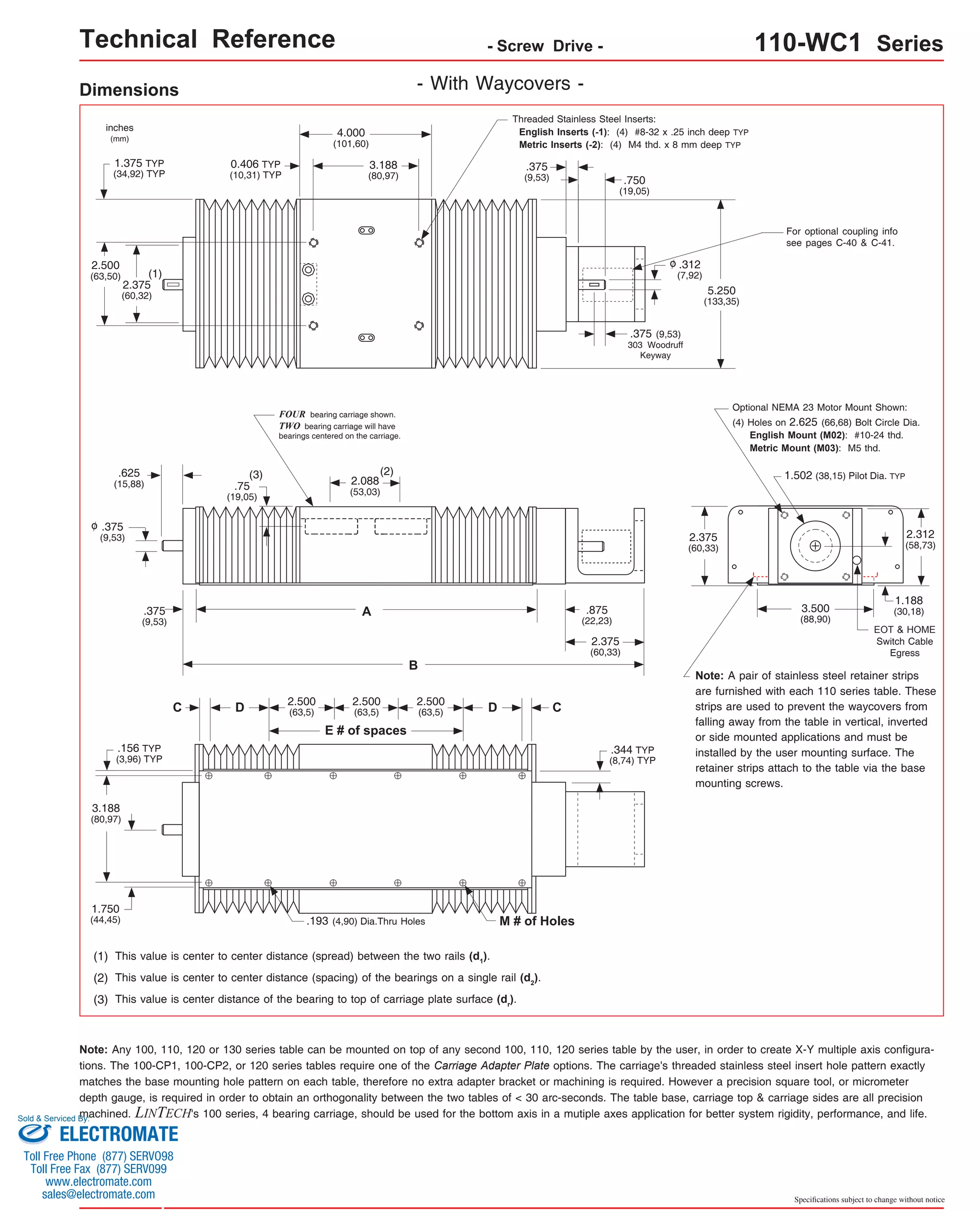
![Technical Reference - Screw Drive - 110-WC1 Series
Travel
Length
Table Dimensions
Model
Number lbs
inches
(mm)
1.250
(31,7) 8 13.25
(337) 4.000 1
(100)
0.250
(6,3) 12 15.25
(387) 5.500 3
(139)
0.250
(6,3) 16 19.25
(489) 8.500 5
(215)
1.250
(31,7) 16 23.25
(591) 11.500 5
(292)
0.750
(19,0) 20 27.25
(692) 14.375 7
(365)
0.250
(6,3) 24 31.25
(794) 17.375 9
(441)
0.750
(19,0) 28 37.25
(946) 22.000 11
(558)
1.250
(31,7) 32 43.25
(1099) 28.000 13
(711)
1.750
(44,4) 36 49.25
(1251) 31.750 15
(806)
2.250
(57,1) 40 55.25
(1403) 36.375 17
(923)
0.250
(6,3) 48 61.25
(1556) 40.750 21
(1035)
0.750
(19,0) 52 67.25
(1708) 45.500 23
(1155)
Footnotes:
Sold & Serviced By:
Specifications subject to change without notice
(kg)
inches
(mm)
C
inches
(mm)
Mounting Dimensions
A
11x401-WC1
6.250
6.3
(158,7)
(2,9) B
9.875
(250,8)
0.500
(12,7)
E M
8
Screw
Length
inches
(mm)
9.25
(235)
Table
Weight
x = 2; Carriage has 2 bearings; Carriage weight = 1.8 lbs. (0,82 kg)
x = 4; Carriage has 4 bearings; Carriage weight = 2.0 lbs. (0,91 kg)
(1)
1
11x402-WC1 8.250
11.875
0.250
1
8 11.25
7.3
(203,2)
(301,6)
(6,3) (286) (3,3) 1.000
(25)
2.500
(63)
11x404-WC1 10.250
13.875
8.2
(260,3)
(352,4)
(3,7) Dimensions & Specifications
11x405-WC1 12.250
15.875
9.2
(311,1)
(403,2)
(4,2) 11x408-WC1 16.250
19.875
11.1
(412,7)
(504,8)
(5,0) 11x411-WC1 20.250
23.875
13.0
(514,3)
(606,4)
(5,9) 11x414-WC1 24.250
27.875
14.9
(615,9)
(708,0)
(6,8) 11x417-WC1 28.250
31.875
16.9
(717,5)
(809,6)
(7,7) 11x422-WC1 34.250
37.875
19.8
(869,9)
(962,0)
(9,0) 11x428-WC1 40.250
43.875
22.6
(1022,3)
(1114,4)
(10,2) 11x431-WC1 46.250
49.875
25.5
(1174,7)
(1266,8)
(11,6) 11x436-WC1 52.250
55.875
28.4
(1327,1)
(1419,2)
(12,9) 11x440-WC1 58.250
61.875
31.3
(1479,5)
(1571,6)
(14,2) 11x445-WC1 64.250
67.875
34.1
(1631,9)
(1724,0)
(15,5) - With Waycovers -
D
1.250
(31,7)
2.500
(63,5)
2.500
(63,5)
2.000
(50,8)
1.500
(38,1)
2.500
(63,5)
2.500
(63,5)
2.500
(63,5)
2.500
(63,5)
2.500
(63,5)
2.500
(63,5)
2.500
(63,5)
2.500
(63,5)
2.500
(63,5)
(1)
Weight shown is with a 0.625 inch (16 mm) diameter screw, a 2 bearing carriage [1.8 lbs (0,82 kg)], a NEMA 23 motor mount [0.34 lbs (0,16 kg)], and a
C100 style [0.09 lbs (0,04 kg)] coupling. When using a 0.500 inch diameter screw subtract 0.022 lbs per inch (0,00039 kg per mm) of screw length for a
given model number. When using a 4 bearing carriage add 0.2 lbs (0,09 kg) to each value.
version: 01/2014
ELECTROMATE
Toll Free Phone (877) SERVO98
Toll Free Fax (877) SERV099
www.electromate.com
sales@electromate.com](https://image.slidesharecdn.com/lintechpositioningsystemscatalog-141018113223-conversion-gate01/75/Lintech-positioning-systems_catalog-115-2048.jpg)

![Technical Reference - Belt Drive - 120-CP0 Series
Dimensions & Specifications
Travel
Length
Table Dimensions
- Without Cover Plates -
Model
Number lbs
Footnotes:
(1)
(kg)
inches
(mm)
C
inches
(mm)
Mounting Dimensions
8.4
inches
(mm)
A
8.0
(203,2)
B
14.000
(355,6)
0.250
(6,3)
E M
12x4004-CP0 8
(3,8)
Belt
Weight
ounces
(gm)
1.3
(36,8)
Table
Weight
18.000
(457,2)
0.250
(6,3) 12 1.7
2.500
(63,5)
2.500
(63,5)
2.500
(63,5)
2.500
(63,5)
94.000
(2387,6) 72
106.000
(2692,4) 80
118.000
(2997,2) 88
x = 2; Carriage has 2 bearings; Carriage weight = 1.6 lbs. (0,73 kg)
x = 4; Carriage has 4 bearings; Carriage weight = 1.8 lbs. (0,82 kg)
(1)
1
Specifications subject to change without notice
9.1
12x4006-CP0 (4,1) 10.0
(254,0)
16.000
(406,4)
1.250
(31,7) 8 1.5
1 (42,5)
4
(100)
6
(150)
9.8
12x4008-CP0 8
12.0
(200)
(304,8)
3 (48,2) (4,4) 11.1
12x4012-CP0 (5,0) 16.0
(406,4)
22.000
(558,8)
0.250
(6,3) 16 2.1
5 (59,5) 12
(300)
12.4
12x4016-CP0 (5,6) 20.0
(508,0)
26.000
(660,4)
1.250
(31,7) 16 2.5
5 (70,9) 16
(405)
13.7
12x4020-CP0 (6,2) 24.0
(609,6)
30.000
(762,0)
0.750
(19,0) 20 2.9
7 (82,2) 20
(505)
15.1
12x4024-CP0 (6,8) 28.0
(711,2)
34.000
(863,6)
0.250
(6,3) 24 3.3
9 (93,6) 24
(605)
17.1
12x4030-CP0 (7,8) 34.0
(863,6)
40.000
(1016,0)
0.750
(19,0) 28 3.9
11 (110,6) 30
(760)
19.1
12x4036-CP0 (8,7) 40.0
(1016,0)
46.000
(1168,4)
1.250
(31,7) 32 4.5
13 (127,6) 36
(910)
21.1
12x4042-CP0 (9,6) 46.0
(1168,4)
52.000
(1320,8)
1.750
(44,4) 36 5.1
15 (144,6) 42
(1060)
35.1
12x4084-CP0 84
88.0
9.3
(2130)
(2235,2)
33 (263,7)
(15,9) 39.1
12x4096-CP0 96
100.0
10.5
(2435)
(2540,0)
37 (297,7)
(17,7) 43.1
12x4108-CP0 108
112.0
11.7
(2740)
(2844,8)
41 (331,7)
(19,6) 47.1
12x4120-CP0 (21,4) 124.0
(3149,6)
130.000
(3302,0) 100 12.9
47 (365,7) 120
(3045)
D
2.500
(63,5)
2.500
(63,5)
2.000
(50,8)
1.500
(38,1)
2.500
(63,5)
2.500
(63,5)
2.500
(63,5)
2.500
(63,5)
2.500
(63,5)
2.500
(63,5)
23.1
12x4048-CP0 (10,4) 52.0
(1320,8)
58.000
(1473,2)
2.250
(57,1) 40
5.7
17 (161,6) 48
(1215)
25.1
12x4054-CP0 (11,4) 58.0
(1473,2)
64.000
(1625,6)
0.250
(6,3) 48
6.3
21 (178,6) 54
(1370)
12x4060-CP0 64.0
(1625,6)
70.000
(1778,0)
0.750
(19,0) 52
6.9
23 (195,6) 60
(1520)
31.1
12x4072-CP0 (14,1) 76.0
(1930,4)
82.000
(2082,8)
1.750
(44,4) 60
8.1
27 (229,6) 72
(1820)
27.1
(12,3)
2.500
(63,5)
2.500
(63,5)
2.500
(63,5)
2.500
(63,5)
0.250
(6,3)
1.250
(31,7)
2.250
(57,1)
0.750
(19,0)
Weight shown is with a 2 bearing carriage [1.6 lbs (0,73 kg)], a NEMA 23 motor mount [0.34 lbs (0,16 kg)], and a H100 style [0.08 lbs (0,04 kg)] coupling.
When using a 4 bearing carriage add 0.2 lbs (0,09 kg) to each value.
version: 01/2014](https://image.slidesharecdn.com/lintechpositioningsystemscatalog-141018113223-conversion-gate01/75/Lintech-positioning-systems_catalog-129-2048.jpg)
![Technical Reference - Belt Drive - 120-CP1 Series
Dimensions & Specifications
Travel
Length
Table Dimensions
- With Top Cover Plate Only -
Model
Number lbs
inches
(mm)
A
8.0
(203,2)
B
14.000
(355,6)
0.250
(6,3)
E M
18.000
(457,2)
D
2.500
(63,5)
2.500
(63,5)
2.000
(50,8)
1.500
(38,1)
2.500
(63,5)
2.500
(63,5)
2.500
(63,5)
2.500
(63,5)
2.500
(63,5)
2.500
(63,5)
0.250
(6,3) 12 1.7
2.500
(63,5)
2.500
(63,5)
2.500
(63,5)
2.500
(63,5)
Footnotes:
(1) For travels greater than 72 inches (1820 mm) a cover plate (-CP1) cannot be used due to the sag of the cover plate.
(2)
(kg)
inches
(mm)
C
inches
(mm)
Mounting Dimensions
8.4
12x4004-CP1 8
(3,8)
Belt
Weight
ounces
(gm)
1.3
(36,8)
Table
Weight
x = 2; Carriage has 2 bearings; Carriage weight = 1.6 lbs. (0,73 kg)
x = 4; Carriage has 4 bearings; Carriage weight = 1.8 lbs. (0,82 kg)
(2)
1
Sold & Serviced By:
Specifications subject to change without notice
9.1
12x4006-CP1 (4,1) 10.0
(254,0)
16.000
(406,4)
1.250
(31,7) 8 1.5
1 (42,5)
4
(100)
6
(150)
9.8
12x4008-CP1 8
12.0
(200)
(304,8)
3 (48,2) (4,4) 11.1
12x4012-CP1 (5,0) 16.0
(406,4)
22.000
(558,8)
0.250
(6,3) 16 2.1
5 (59,5) 12
(300)
12.4
12x4016-CP1 (5,6) 20.0
(508,0)
26.000
(660,4)
1.250
(31,7) 16 2.5
5 (70,9) 16
(405)
13.7
12x4020-CP1 (6,2) 24.0
(609,6)
30.000
(762,0)
0.750
(19,0) 20 2.9
7 (82,2) 20
(505)
15.1
12x4024-CP1 (6,8) 28.0
(711,2)
34.000
(863,6)
0.250
(6,3) 24 3.3
9 (93,6) 24
(605)
17.1
12x4030-CP1 (7,8) 34.0
(863,6)
40.000
(1016,0)
0.750
(19,0) 28 3.9
11 (110,6) 30
(760)
19.1
12x4036-CP1 (8,7) 40.0
(1016,0)
46.000
(1168,4)
1.250
(31,7) 32 4.5
13 (127,6) 36
(910)
21.1
12x4042-CP1 (9,6) 46.0
(1168,4)
52.000
(1320,8)
1.750
(44,4) 36 5.1
15 (144,6) 42
(1060)
23.1
12x4048-CP1 (10,4) 52.0
(1320,8)
58.000
(1473,2)
2.250
(57,1) 40
5.7
17 (161,6) 48
(1215)
25.1
12x4054-CP1 (11,4) 58.0
(1473,2)
64.000
(1625,6)
0.250
(6,3) 48
6.3
21 (178,6) 54
(1370)
12x4060-CP1 64.0
(1625,6)
70.000
(1778,0)
0.750
(19,0) 52
6.9
23 (195,6) 60
(1520)
31.1
12x4072-CP1 (14,1) 76.0
(1930,4)
82.000
(2082,8)
1.750
(44,4) 60
8.1
27 (229,6) 72
(1820)
27.1
(12,3)
(1)
Weight shown is with a 2 bearing carriage [1.6 lbs (0,73 kg)], a NEMA 23 motor mount [0.34 lbs (0,16 kg)], and a H100 style [0.08 lbs (0,04 kg)] coupling.
When using a 4 bearing carriage add 0.2 lbs (0,09 kg) to each value.
ELECTROMATE
Toll Free Phone (877) SERVO98
Toll Free Fax (877) SERV099
www.electromate.com
sales@electromate.com](https://image.slidesharecdn.com/lintechpositioningsystemscatalog-141018113223-conversion-gate01/75/Lintech-positioning-systems_catalog-131-2048.jpg)
![Technical Reference - Belt Drive - 120 Series
Master/Slave 120 Series Configuration
For some X-Y belt drive applications, the
master/slave configuration shown to the right
may be required. This system provides two bot-tom
(X) axes spread apart a set distance, yet
driven by one motor. The spreading of the two
bottom axes minimizes the deflection on the Y
axis, reduces the moment loading on the X axes
carriages, increases the system rigidity, and
prevents twisting of the Y axis as it accelerates
to a set speed. LINTECH can provide the shaft
supports, the cross shaft, the couplings, and
the 120 series belt drive table without a motor
mount bracket. The shaft supports are required
as the couplings DO NOT provide adequate
support of the shaft by themselves. Also, the
shaft supports prevent the cross shaft from
"whipping" at long lengths and high speeds.
The chart below lists the maximum carriage
speed available with a given distance between
shaft supports. A minimum of two shaft supports
is always required. More than two can be used
to increase the speed of a longer spread sys-tem.
The equations below show the relationship
between the # of shaft supports, the spread be-tween
the two bottom axes (B), and the distance
between individual shaft supports (A).
A
(see chart)
Shaft Supports (44192)
B - 2.25
(B - 57,15)
(required shaft length)
Max. Ref.
C191 coupling C191 coupling
B
Shaft Supports (44192)
1.030
(26,16)
C' Bore for 1/4-20 (M6)
socket head cap screw
Steel Cross Shaft: 0.500 inch (12,7 mm) diameter;
0.055 lbs/in (0,00098 kg/mm);
Rockwell 60-65C
Example #1: Above configuration with Y axis and 2 extended carriage adapter
plates.
Example #2: Above configuration with Y axis, 2 extended carriage adapter
plates, and 2 horizontal angle brackets.
A = distance between shaft supports
B = distance between 2 bottom axes
Maximum
Distance Between
Shaft Supports
(inches) (RPM)
30
36
48
<=
<=
<=
(in/sec)
54
60
66
<=
<=
<=
72
84
96
<=
<=
<=
108
<=
<= 120
118
89
50
39
32
26
22
16
12
10
8
2000
1500
840
660
535
440
370
270
208
164
133
A
Maximum
Shaft
Speed
Equivalent
Carriage
Speed
2 Shaft Supports:
3 Shaft Supports:
4 Shaft Supports:
A = [B - 7.50 in (190,5 mm)]
A = [B - 8.53 in (216,7 mm)] / 2
A = [B - 9.56 in (242,8 mm)] / 3
Note: The user is required to supply the mounting surface
for the above configurations. LINTECH normally only sup-plies
all the positioning hardware. A common base plate can
be provided by LINTECH upon request.
Specifications subject to change without notice
(mm)
762
914
1219
1372
1524
1676
1829
2134
2438
2743
3048
(mm/sec)
3000
2250
1260
990
802
660
555
405
312
246
200
inches
(mm) 1.000
(25,4)
1.000 Max. Ref.
(25,4)
2.000
(50,8)
1.375
(34,93)
2.530
(64,26)
2.530
(75,57)
2.465
(62,61)](https://image.slidesharecdn.com/lintechpositioningsystemscatalog-141018113223-conversion-gate01/75/Lintech-positioning-systems_catalog-134-2048.jpg)


![Options - Screw & Belt Drive - 100, 110 & 120 Series
Carriage Adapter Plates
Optional carriage adapter plates assist in the creation of simple X-Y, X-Z, and X-Y-Z multiple axis systems. The regular car-riage
adapter plate can be used by either the 100-CP1, 100-CP2, or 120 series tables, while the extended adapter plate can be
used with the 100, 110, or 120 series tables. The extended carriage adapter plate can be used in applications to increase the Y
axis travel without having to use a longer travel table. A precision square tool, or micrometer depth gauge, is required in order
to obtain an orthogonality between the two tables of < 30 arc-seconds.
Threaded Stainless Steel Inserts:
English Mount (part # 43551): (4) #8-32 x .25 inch deep TYP
Metric Mount (part # 202297): (4) M4 thd. x 6,35 mm deep TYP
.193 (4,90) Dia.Thru Holes,
C' Bored .312 (7,92) Dia. x .190 (4,83) Deep
3.875
(98,43)
3.188
(80,98)
.344
(8,74)
3.500
(88,90)
.188
(4,78)
2.500
(63,50)
3.125
(79,38)
3.500
(88,90)
.500
(12,70)
.188
(4,78)
Weight
.50 lbs
(0,23 kg)
inches
(mm)
Thick
.375
(9,53)
Regular Carriage Adapter Plate
Threaded Stainless Steel Inserts:
English Mount (part # 44384): (4) #8-32 x .375 inch deep TYP
Metric Mount (part # 202298): (4) M4 thd. x 9,53 mm deep TYP
.193 (4,90) Dia.Thru Holes,
C' Bored .312 (7,92) Dia. x .190 (4,83) Deep
Weight
1.1 lbs
(0,50 kg)
inches
(mm)
Thick
.375
(9,53)
Extended Carriage Adapter Plate
3.875
(98,43)
.188
(4,78)
.500
(12,70)
3.188
(80,98)
.188
(4,78)
3.500
(88,90)
3.125
(79,38)
2.500
(63,50)
.344
(8,74)
3.500
(88,90)
4.000
(101,60)
7.000
(177,80)
2.500
(63,50)
3.188
(80,98)
3.500
(88,90)
.344
(8,72)
.188
(4,76)
Material
Aluminum
Material
Aluminum
* Subtract an additional 0.875 inches (22,22 mm) from the above values if a 110 series table is used as the bottom axis.
* If a 110 series table is used as the top axis, the Y travel distance is the same as the 110 series table travel due to the waycovers.
Sold & Serviced By:
Specifications subject to change without notice
Y
Notes:
(1) Above Y travel distance (need to refer to Base Mounting Dimensions on pages C-6, C-8, C-10, C-14 & C-28):
For D dimension = 2.50 inches (63,5 mm): Y = [table travel length] - [C dimension] + [0.50 inches (12,7 mm)]
For D dimension < 2.50 inches (63,5 mm): Y = [table travel length] - [C dimension] - [D dimension] + [0.50 inches (12,7 mm)]
The extended carriage adapter plate works with all top axis tables that use the optional NEMA 23 motor mount. Care should be taken if the optional NEMA
34 motor mount, or any other motor mount is used on the top axis table. The motor mount could extend below the table base, thus interfering with the
extended carriage adapter plate.
*
ELECTROMATE
Toll Free Phone (877) SERVO98
Toll Free Fax (877) SERV099
www.electromate.com
sales@electromate.com](https://image.slidesharecdn.com/lintechpositioningsystemscatalog-141018113223-conversion-gate01/75/Lintech-positioning-systems_catalog-145-2048.jpg)

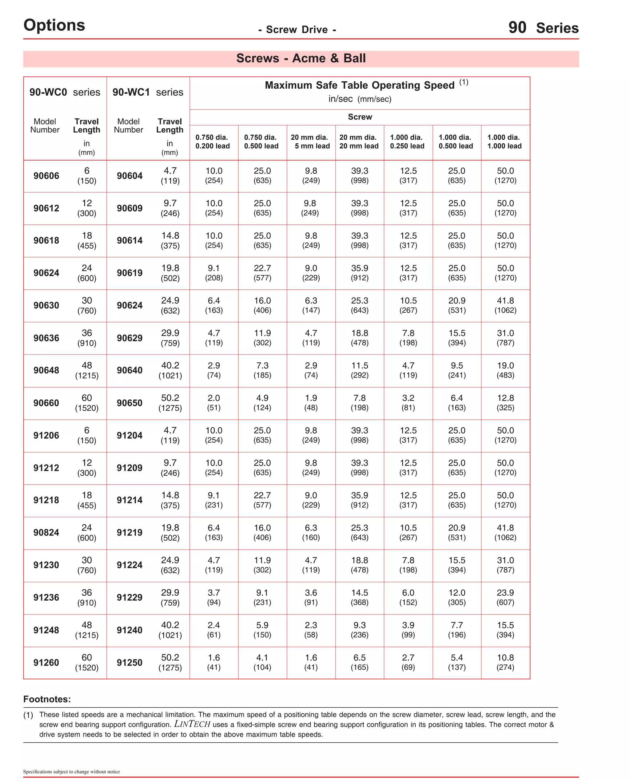
![Technical Reference - Screw Drive - 90-WC0 Series
Dimensions & Specifications - Without Waycovers -
Travel
Length
Table Dimensions
Screw
Length
Model
Number lbs
inches
(mm)
6
(150)
12
(300)
E
B
15.75
(400,0)
19.25
(488,9)
21.75
(552,4)
inches
(mm)
14.94
(379,4)
20.94
(531,9)
26.94
(684,3)
32.94
(836,7)
38.94
(989,1)
44.94
(1141,5)
56.94
(1446,3)
68.94
(1751,1)
C
10.00
(254,0)
16.00
(406,4)
22.00
(558,8)
28.00
(711,2)
34.00
(863,6)
40.00
(1016,0)
52.00
(1320,8)
64.00
(1625,6)
16.00
(406,4)
22.00
(558,8)
28.00
(711,2)
34.00
(863,6)
40.00
(1016,0)
46.00
(1168,4)
58.00
(1473,2)
70.00
(1778,0)
6.00
(152,4)
4.00
(101,6)
90612-WC0 8 (7,6)
18
(455)
25.25
(641,3)
27.75
(704,8)
See Detail 1
90618-WC0 10 (9,1)
24
(605)
31.25
(793,7)
33.75
(857,2)
See Detail 2
90624-WC0 14 (14,1)
30
(760)
37.25
(946,1)
39.75
(1009,6)
See Detail 3
90630-WC0 16 (16,3)
36
(910)
43.25
(1098,5)
45.75
(1162,0)
See Detail 4
90636-WC0 18 (18,6)
48
(1215)
55.25
(1403,3)
57.75
(1466,8)
See Detail 5
90648-WC0 24 (23,1)
60
(1520)
67.25
(1708,1)
69.75
(1771,6)
See Detail 7
90660-WC0 28 (27,7)
6
(150)
19.25
(488,9)
21.75
(552,4)
20.94
(531,9)
26.94
(684,3)
32.94
(836,7)
38.94
(989,1)
44.94
(1141,5)
See Detail 9
91206-WC0 8 (9,7)
12
(300)
25.25
(641,3)
27.75
(704,8)
See Detail 1
91212-WC0 10 (10,7)
18
(455)
31.25
(793,7)
33.75
(857,2)
See Detail 2
91218-WC0 14 (15,0)
24
(605)
37.25
(946,1)
39.75
(1009,6)
See Detail 3
91224-WC0 16 (17,2)
30
(760)
43.25
(1098,5)
45.75
(1162,0)
See Detail 4
91230-WC0 18
36
(910)
43.0
(19,5)
49.25
(1250,9)
51.75
(1466,8)
50.94
(1293,9)
See Detail 5
91236-WC0 24 (21,8)
48
(1215)
33.0
38.0
48.0
61.25
(1555,7)
63.75
(1619,2)
62.94
(1598,7)
74.94
(1903,5)
See Detail 6
91248-WC0 28 (26,3)
60
(1520)
73.25
(1860,5)
75.75
(1924,0)
See Detail 8
91260-WC0 30 (30,8)
Sold & Serviced By:
Specifications subject to change without notice
(kg)
inches
(mm)
D
inches
(mm)
Mounting Dimensions
13.3
A
13.25
(336,5)
M
90606-WC0 6
(6,0)
Table
Weight
16.8
20.0
31.0
36.0
41.0
51.0
61.0
21.3
23.5
58.0
68.0
See Detail 10
06 = Carriage length is 06 inch (152,4 mm) with 4 bearings; Carriage weight = 5.25 lbs. (2,38 kg)
12 = Carriage length is 12 inch (304,8 mm) with 4 bearings; Carriage weight = 8.00 lbs. (3,63 kg)
(1)
Footnotes:
(1) Weight shown is with a 0.625 inch (16 mm) diameter screw, a NEMA 23 motor mount [0.34 lbs (0,16 kg)], and a C100 style [0.09 lbs (0,04 kg)] coupling.
When using a 0.750 inch (20 mm) diameter screw add 0.042 lbs per inch (0,00075 kg per mm) of screw length for a given model number. When using a
1.000 inch diameter screw add 0.117 lbs per inch (0,0021 kg per mm) of screw length for a given model number.
version: 01/2014
ELECTROMATE
Toll Free Phone (877) SERVO98
Toll Free Fax (877) SERV099
www.electromate.com
sales@electromate.com](https://image.slidesharecdn.com/lintechpositioningsystemscatalog-141018113223-conversion-gate01/75/Lintech-positioning-systems_catalog-157-2048.jpg)
![Technical Reference - Screw Drive - 90-WC0 Series
Dimensions - Without Waycovers -
1.125
(28,58)
1.625 D E
(41,28)
6 inch (152,4 mm) FOUR bearing carriage shown.
12 inch (304,8 mm) FOUR bearing carriage will have
individual bearings mounted towards carriage edges.
X
Optional NEMA 23 Motor Mount Shown:
(1) This value is center to center distance (spread)
between the two rails (d1).
(2) This value is center to center distance (spacing) of
the bearings on a single rail (d2) [see page D-5].
Specifications subject to change without notice
(2)
See Detail 1 - 10 (below)
A
B
(3)
Threaded Stainless Steel Inserts:
English Inserts (-1): 1/4-20 x .50 inch deep TYP
Metric Inserts (-2): M6 thd. x 12 mm deep TYP
5.000
(127,00)
EOT & HOME
Switch Cable Egress 1.502 (38,15) Pilot Dia. TYP
5.500
(139,70)
3.250
(82,55)
4.500
(114,30)
5.500
(139,70)
.625
(15,87)
2.937
(74,60)
.500
(12,70)
(4) Holes on 2.625 (66,68) Bolt Circle Dia.
English Mount (M02): #10-24 thd.
Metric Mount (M03): M5 thd.
inches
(mm)
.375
(9,53)
0.500 TYP
(12,70) TYP
1.250
(31,75)
o
1.068
(27,13)
.375
(9,52)
o
.375 (9,53)
304 Woodruff
Keyway
(1)
8.000
(203,2)
d2
.625
(15,87)
C
M # of Thru Holes
.201 (5,11) Dia.
Mounting Details 1 through 10
1.625
(41,28)
W W 1.625
(41,28)
X
2
3
4
5
7
9
10
1.437
(36,50)
2.438
(61,93)
4 Holes; 6 inch (152,4 mm) carriage
Carriage Length
6 Holes; 12 inch (304,8 mm) carriage
.625
(15,87)
For optional coupling info
see pages D-26 & D-27.
Also, coupling cover in-cluded
on top of optional
motor mounts.
X
1.625
(41,28)
Z
Z
Z
Z
Z Z
Z
W 1.625
(41,28)
X X W
Z
W X X W W X X W
1.625
(41,28)
1.625
(41,28)
1.625
(41,28)
W 1.625
(41,28)
X X W W X X W
1.625
(41,28)
W 1.625
(41,28)
X X W W X X
1.625
(41,28)
W 1.625
(41,28)
W Y X X W
1.625
(41,28)
W 1.625
(41,28)
Y X X
(3) This value is center distance of the bearing to top of
carriage plate surface (dr).
Note: Any 90 series table can be mounted on top
of any second 90 series, in order to create X-Y
multiple axis configurations. The carriage's threaded
stainless steel insert hole pattern DOES NOT ex-actly
match the base mounting hole pattern on each
table, therefore machining of the bottom axis car-riage
plate is required. Please contact LINTECH.
W = 6.00
(152,4) X = 5.00
(127,0)
Y = 4.00
(101,6) Z = 2.00
(50,8)
Z
Z Z
1.625
(41,28)
W 1.625
(41,28)
X
1
Y
6
1.625
(41,28)
W 1.625
(41,28)
X X W W X X
8
1.625
(41,28)
W 1.625
(41,28)
X X W W X X W
Y
W
W
W
X X W
Z
W X X W W X X W](https://image.slidesharecdn.com/lintechpositioningsystemscatalog-141018113223-conversion-gate01/75/Lintech-positioning-systems_catalog-158-2048.jpg)
![Technical Reference - Screw Drive - 90-WC1 Series
Dimensions & Specifications - With Waycovers -
Travel
Length
Table Dimensions
Screw
Length
Model
Number lbs
inches
(mm)
4.7
(119)
9.7
(246)
E
B
15.75
(400,0)
19.25
(488,9)
21.75
(552,4)
inches
(mm)
C
10.00
(254)
16.00
(406,4)
22.00
(558,8)
28.00
(711,2)
34.00
(863,6)
40.00
(1016,0)
52.00
(1320,8)
64.00
(1625,6)
16.00
(406,4)
22.00
(558,8)
28.00
(711,2)
34.00
(863,6)
40.00
(1016,0)
46.00
(1168,4)
58.00
(1473,2)
70.00
(1778,0)
14.94
(379,4)
20.94
(531,9)
26.94
(684,3)
32.94
(836,7)
38.94
(989,1)
44.94
(1141,5)
56.94
(1446,3)
68.94
(1751,1)
6.00
(152,4)
4.00
(101,6)
90609-WC1 (8,3)
25.25
(641,3)
27.75
(704,8)
8
See Detail 1
90614-WC1 (9,9) 14.8
(375)
31.25
(793,7)
33.75
(857,2)
10
See Detail 2
90619-WC1 (15,1) 19.8
(502)
37.25
(946,1)
39.75
(1009,6)
14
See Detail 3
90624-WC1 (17,5) 24.9
(632)
43.25
(1098,5)
45.75
(1162,0)
16
See Detail 4
90629-WC1 (20,0) 29.9
(759)
55.25
(1403,3)
57.75
(1466,8)
18
See Detail 5
90640-WC1 (24,9) 40.2
(1021)
67.25
(1708,1)
69.75
(1771,6)
24
See Detail 7
90650-WC1 (29,8) 50.2
(1275)
19.25
(488,9)
21.75
(552,4)
20.94
(531,9)
26.94
(684,3)
32.94
(836,7)
38.94
(989,1)
44.94
(1141,5)
28
See Detail 9
91204-WC1 (10,1) 4.7
(119)
25.25
(641,3)
27.75
(704,8)
8
See Detail 1
91209-WC1 (11,3) 9.7
(246)
34.8
31.25
(793,7)
33.75
(857,2)
10
See Detail 2
91214-WC1 (15,8) 14.8
(375)
40.2
37.25
(946,1)
39.75
(1009,6)
14
See Detail 3
91219-WC1 (18,2) 19.8
(502)
91224-WC1 24.9
(632)
45.6
(20,7)
51.0
43.25
(1098,5)
45.75
(1162,0)
49.25
(1250,9)
51.75
(1466,8)
50.94
(1293,9)
16
18
See Detail 4
See Detail 5
91229-WC1 (23,1) 29.9
(759)
61.25
(1555,7)
63.75
(1619,2)
62.94
(1598,7)
74.94
(1903,5)
24
See Detail 6
91240-WC1 (28,1) 40.2
(1021)
73.25
(1860,5)
75.75
(1924,0)
28
See Detail 8
91250-WC1 (33,0) 50.2
(1275)
Specifications subject to change without notice
(kg)
inches
(mm)
D
inches
(mm)
Mounting Dimensions
14.2
A
13.25
(336,5)
M
90604-WC1 6
(6,5)
Table
Weight
18.2
21.8
33.2
38.6
44.0
54.9
65.7
22.3
24.9
61.9
72.7
30
See Detail 10
06 = Carriage length is 06 inch (152,4 mm) with 4 bearings; Carriage weight = 5.75 lbs. (2,61 kg)
12 = Carriage length is 12 inch (304,8 mm) with 4 bearings; Carriage weight = 8.75 lbs. (3,97 kg)
(1)
Footnotes:
(1) Weight shown is with a 0.625 inch (16 mm) diameter screw, a NEMA 23 motor mount [0.34 lbs (0,16 kg)], and a C100 style [0.09 lbs (0,04 kg)] coupling.
When using a 0.750 inch (20 mm) diameter screw add 0.042 lbs per inch (0,00075 kg per mm) of screw length for a given model number. When using a
1.000 inch diameter screw add 0.117 lbs per inch (0,0021 kg per mm) of screw length for a given model number.](https://image.slidesharecdn.com/lintechpositioningsystemscatalog-141018113223-conversion-gate01/75/Lintech-positioning-systems_catalog-159-2048.jpg)
![Technical Reference - Screw Drive - 90-WC1 Series
Optional NEMA 23 Motor Mount Shown:
(1) This value is center to center distance (spread)
between the two rails (d1).
(2) This value is center to center distance (spacing) of
the bearings on a single rail (d2) [see page D-5].
Specifications subject to change without notice
Dimensions - With Waycovers -
1.125
(28,58)
1.625 D E
(41,28) M # of Thru Holes
C
6 inch (152,4 mm) FOUR bearing carriage shown.
12 inch (304,8 mm) FOUR bearing carriage will have
individual bearings mounted towards carriage edges.
(2)
(3)
Threaded Stainless Steel Inserts:
English Inserts (-1): 1/4-20 x .50 inch deep TYP
Metric Inserts (-2): M6 thd. x 12 mm deep TYP
5.000
(127,00)
EOT & HOME
Switch Cable Egress 1.502 (38,15) Pilot Dia. TYP
5.500
(139,70)
3.250
(82,55)
4.500
(114,30)
5.500
(139,70)
2.937
(74,60)
.500
(12,70)
(4) Holes on 2.625 (66,68) Bolt Circle Dia.
English Mount (M02): #10-24 thd.
Metric Mount (M03): M5 thd.
inches
(mm)
.375
(9,53)
0.500 TYP
(12,70) TYP
1.250
(31,75)
o
1.068
(27,13)
.375
(9,52)
o
.375 (9,53)
304 Woodruff
Keyway
(1)
8.000
(203,2)
d2
.201 (5,11) Dia.
1.437
(36,50)
2.438
(61,93)
4 Holes; 6 inch (152,4 mm) carriage
Carriage Length
6 Holes; 12 inch (304,8 mm) carriage
.625
(15,87)
For optional coupling info
see pages D-26 & D-27.
Also, coupling cover in-cluded
on top of optional
motor mounts.
A
B
.625
(15,87)
.625
(15,87)
See Detail 1 - 10 (below)
X Mounting Details 1 through 10
1.625
(41,28)
W W 1.625
(41,28)
X
2
3
4
5
7
9
Sold & Serviced By:
10
X
1.625
(41,28)
Z
Z
Z
Z
Z Z
Z
W 1.625
(41,28)
X X W
Z
W X X W W X X W
1.625
(41,28)
1.625
(41,28)
1.625
(41,28)
W 1.625
(41,28)
X X W W X X W
1.625
(41,28)
W 1.625
(41,28)
X X W W X X
1.625
(41,28)
W 1.625
(41,28)
W Y X X W
1.625
(41,28)
W 1.625
(41,28)
Y X X
(3) This value is center distance of the bearing to top of
carriage plate surface (dr).
Note: Any 90 series table can be mounted on top
of any second 90 series, in order to create X-Y
multiple axis configurations. The carriage's threaded
stainless steel insert hole pattern DOES NOT ex-actly
match the base mounting hole pattern on each
table, therefore machining of the bottom axis car-riage
plate is required. Please contact LINTECH.
W = 6.00
(152,4) X = 5.00
(127,0)
Y = 4.00
(101,6) Z = 2.00
(50,8)
Z
Z Z
1.625
(41,28)
W 1.625
(41,28)
X
1
Y
6
1.625
(41,28)
W 1.625
(41,28)
X X W W X X
8
1.625
(41,28)
W 1.625
(41,28)
X X W W X X W
Y
W
W
W
X X W
Z
W X X W W X X W
ELECTROMATE
Toll Free Phone (877) SERVO98
Toll Free Fax (877) SERV099
www.electromate.com
sales@electromate.com](https://image.slidesharecdn.com/lintechpositioningsystemscatalog-141018113223-conversion-gate01/75/Lintech-positioning-systems_catalog-160-2048.jpg)


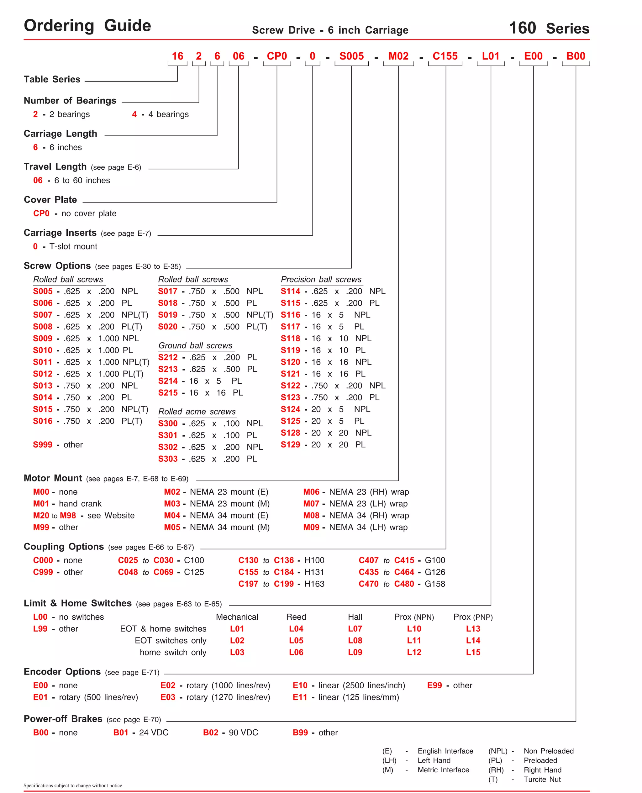
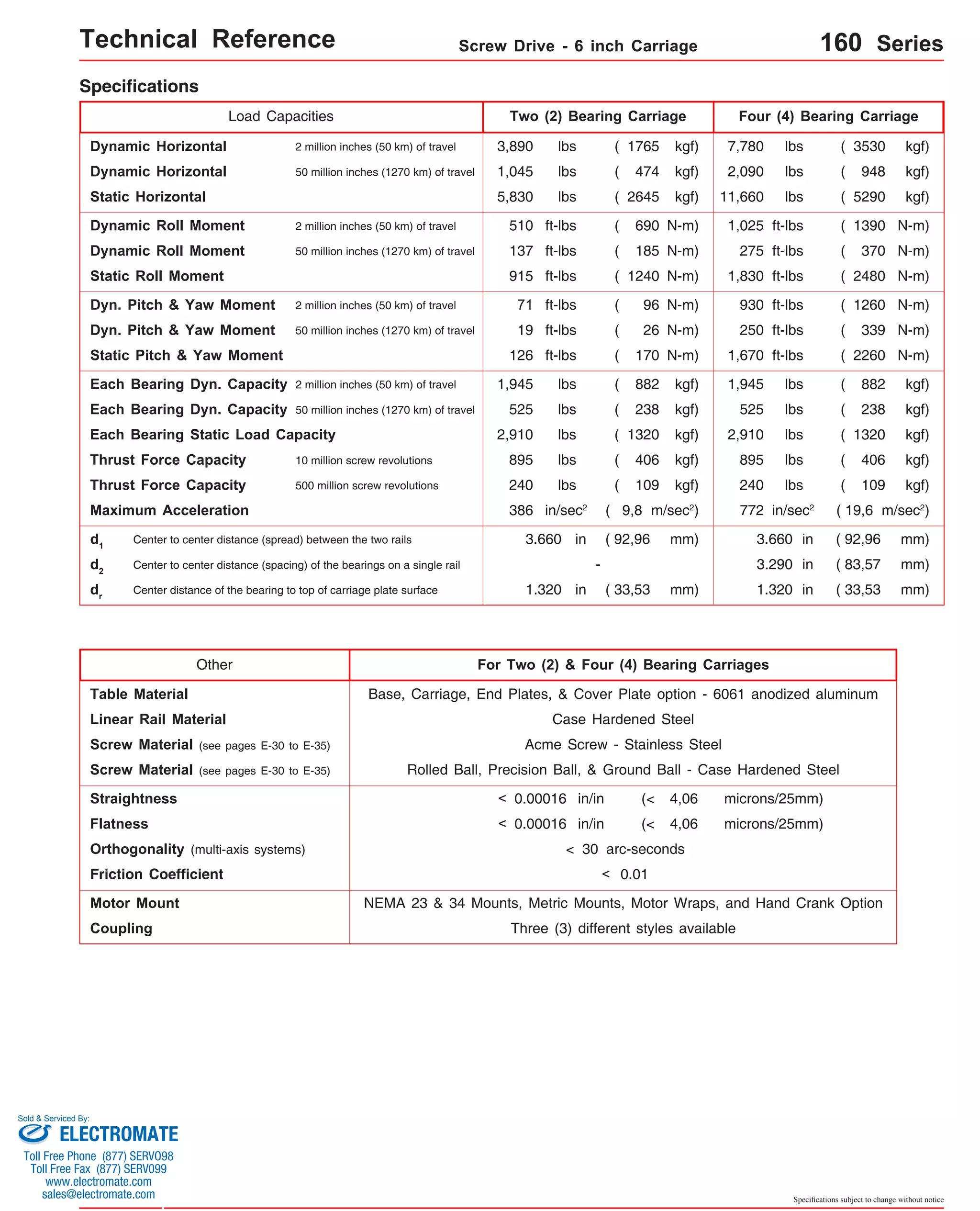
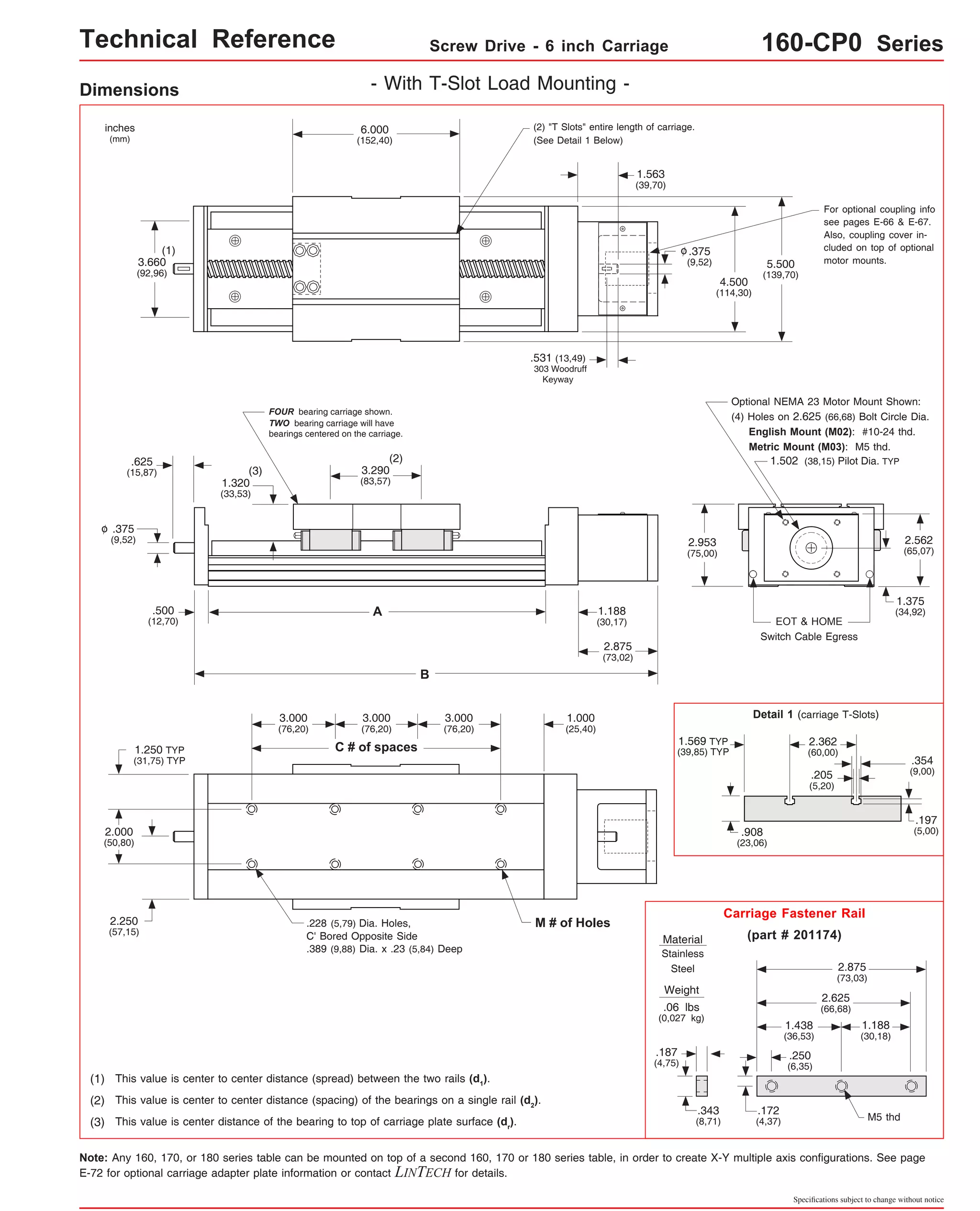
![Technical Reference Screw Drive - 6 inch Carriage 160-CP0 Series
Dimensions & Specifications
Travel
Length
Table Dimensions
Model
Number lbs
inches
(mm)
16x648-CP0 48
(1215)
Sold & Serviced By:
Specifications subject to change without notice
(kg)
inches
(mm)
C
inches
(mm)
Mounting Dimensions
A
16x606-CP0
12.125
14.2
(308,0)
(6,4) B
16.688
(423,9)
Screw
Length
inches
(mm)
16.00
(406)
Table
Weight
54.125
(1374,8)
58.688
(1490,7)
58.00
(1473) 17 36 29.6
(13,4)
x = 2; Carriage has 2 bearings; Carriage weight = 3.3 lbs. (1,50 kg)
x = 4; Carriage has 4 bearings; Carriage weight = 4.1 lbs. (1,86 kg)
(1)
16x612-CP0 18.125
(460,4)
6
(150)
12
(300)
16x618-CP0 18
(455)
16x624-CP0 24
(605)
16x630-CP0 30
(760)
16x636-CP0 36
(910)
16x642-CP0 42
(1060)
16x654-CP0 54
(1370)
16x660-CP0 60
(1520)
- With T-Slot Load Mounting -
M
3 8
22.688
(576,3)
22.00
(559) 5 12
24.125
(612,8)
28.688
(728,7)
28.00
(711) 7 16
30.125
(765,2)
34.688
(881,1)
34.00
(864) 9 20
36.125
(917,6)
40.688
(1033,5)
40.00
(1016) 11 24
42.125
(1070,0)
46.688
(1185,9)
46.00
(1168) 13 28
48.125
(1222,4)
52.688
(1338,3)
52.00
(1321) 15 32
60.125
(1527,1)
64.688
(1643,0)
64.00
(1625) 19 40
66.125
(1679,6)
70.688
(1795,5)
70.00
(1778) 21 44
16.4
(7,4)
18.6
(8,4)
20.8
(9,4)
23.0
(10,4)
25.2
(11,4)
27.4
(12,4)
31.8
(14,4)
34.0
(15,4)
Footnotes:
(1) Weight shown is with a 0.625 inch (16 mm) diameter screw, a NEMA 23 motor mount [0.42 lbs (0,19 kg)], a C100 style [0.09 lbs (0,04 kg)] coupling,
and a 2 bearing carriage. When using a 0.750 inch (20 mm) diameter screw add 0.042 lbs per inch (0,00075 kg per mm) of screw length for a given
model number. When using a 4 bearing carriage add 0.8 lbs (0,36 kg) to each value.
version: 01/2014
ELECTROMATE
Toll Free Phone (877) SERVO98
Toll Free Fax (877) SERV099
www.electromate.com
sales@electromate.com](https://image.slidesharecdn.com/lintechpositioningsystemscatalog-141018113223-conversion-gate01/75/Lintech-positioning-systems_catalog-189-2048.jpg)

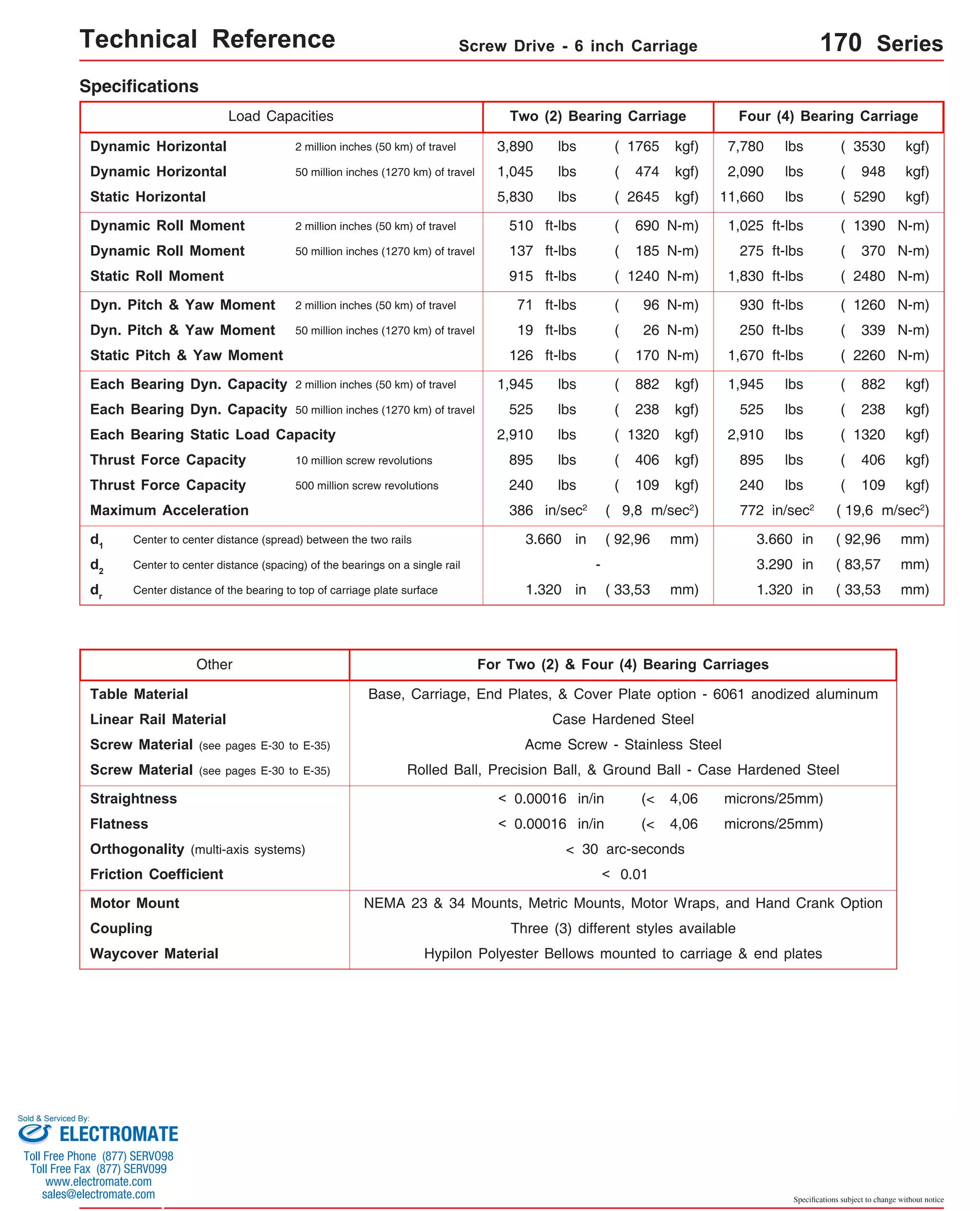
![Technical Reference Screw Drive - 6 inch Carriage 170-CP0 Series
Dimensions & Specifications
Travel
Length
Table Dimensions
Model
Number lbs
17x648-CP0 48
(1215)
17x654-CP0 54
(1370)
Sold & Serviced By:
Specifications subject to change without notice
(kgf)
inches
(mm)
C
inches
(mm)
Mounting Dimensions
17x606-CP0
inches
(mm)
A
B
16.688
(423,9)
Screw
Length
inches
(mm)
Table
Weight
12.125
(308,0)
18.125
(460,4)
24.125
(612,8)
30.125
(765,2)
36.125
(917,6)
42.125
(1070,0)
48.125
(1222,4)
54.125
(1374,8)
60.125
(1527,1)
66.125
(1679,6)
58.688
(1490,7) 17 36 26.8
(12,2)
64.688
(1643,0)
19 40 (1625) 28.6
(13,0)
x = 2; Carriage has 2 bearings; Carriage weight = 2.5 lbs. (1,13 kg)
x = 4; Carriage has 4 bearings; Carriage weight = 3.3 lbs. (1,50 kg)
(1)
17x612-CP0
6
(150)
12
(300)
17x618-CP0 18
(455)
17x624-CP0 24
(605)
17x630-CP0 30
(760)
17x636-CP0 36
(910)
17x642-CP0 42
(1060)
17x660-CP0 60
(1520)
- Without Cover Plates -
M
3 8
22.688
(576,3) 5 12
28.688
(728,7) 7 16
34.688
(881,1) 9 20
40.688
(1033,5) 11 24
46.688
(1185,9) 13 28
52.688
(1338,3) 15 32
70.688
(1795,5) 21 44
14.2
(6,4)
16.0
(7,3)
17.8
(8,1)
19.6
(8,9)
21.4
(9,7)
23.2
(10,5)
25.0
(11,3)
30.4
(13,8)
16.00
(406)
22.00
(559)
28.00
(711)
34.00
(864)
40.00
(1016)
46.00
(1168)
52.00
(1321)
58.00
(1473)
64.00
70.00
(1778)
Footnotes:
(1) Weight shown is with a 0.625 inch (16 mm) diameter screw, a NEMA 23 motor mount [0.42 lbs (0,19 kg)], a C100 style [0.09 lbs (0,04 kg)] coupling,
and a 2 bearing carriage. When using a 0.750 inch (20 mm) diameter screw add 0.042 lbs per inch (0,00075 kg per mm) of screw length for a given
model number. When using a 4 bearing carriage add 0.8 lbs (0,36 kg) to each value.
version: 01/2014
ELECTROMATE
Toll Free Phone (877) SERVO98
Toll Free Fax (877) SERV099
www.electromate.com
sales@electromate.com](https://image.slidesharecdn.com/lintechpositioningsystemscatalog-141018113223-conversion-gate01/75/Lintech-positioning-systems_catalog-193-2048.jpg)
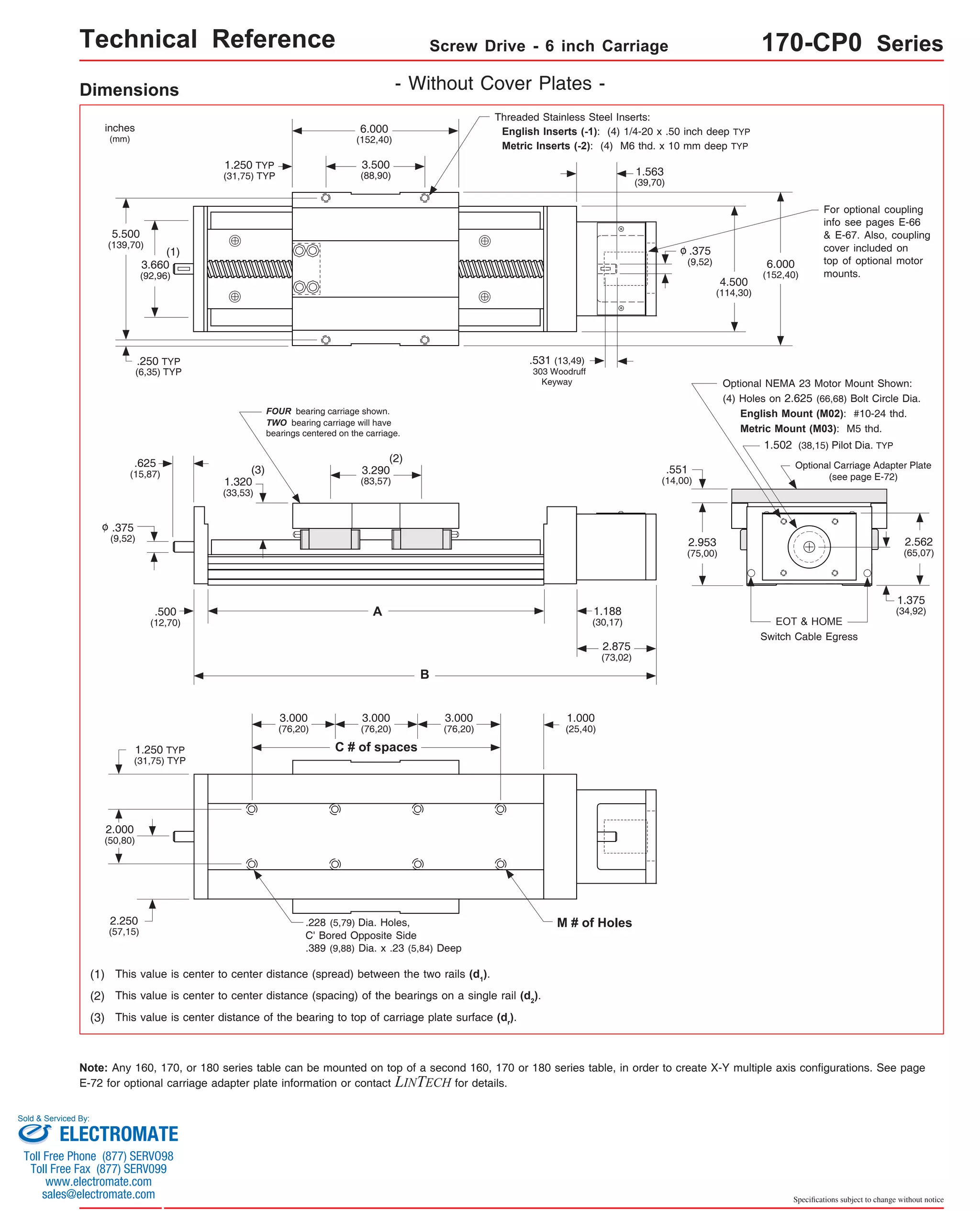
![Technical Reference Screw Drive - 6 inch Carriage 170-CP1 Series
Dimensions & Specifications
Travel
Length
Table Dimensions
Model
Number lbs
17x648-CP1 48
(1215)
17x654-CP1 54
(1370)
Sold & Serviced By:
Specifications subject to change without notice
(kg)
inches
(mm)
C
inches
(mm)
Mounting Dimensions
17x606-CP1
inches
(mm)
A
B
16.688
(423,9)
Screw
Length
inches
(mm)
Table
Weight
12.125
(308,0)
18.125
(460,4)
24.125
(612,8)
30.125
(765,2)
36.125
(917,6)
42.125
(1070,0)
48.125
(1222,4)
54.125
(1374,8)
60.125
(1527,1)
66.125
(1679,6)
58.688
(1490,7) 17 36 30.4
(13,8)
64.688
(1643,0)
19 40 (1625) 32.6
(14,8)
x = 2; Carriage has 2 bearings; Carriage weight = 2.5 lbs. (1,13 kg)
(1)
17x612-CP1
6
(150)
12
(300)
17x618-CP1 18
(455)
17x624-CP1 24
(605)
17x630-CP1 30
(760)
17x636-CP1 36
(910)
17x642-CP1 42
(1060)
17x660-CP1 60
(1520)
- With Top Cover Plate Only -
M
3 8
22.688
(576,3) 5 12
28.688
(728,7) 7 16
34.688
(881,1) 9 20
40.688
(1033,5) 11 24
46.688
(1185,9) 13 28
52.688
(1338,3) 15 32
70.688
(1795,5) 21 44
x = 4; Carriage has 4 bearings; Carriage weight = 3.3 lbs. (1,50 kg)
15.0
(6,8)
17.2
(7,8)
19.4
(8,8)
21.6
(9,8)
23.8
(10,8)
26.0
(11,8)
28.2
(12,8)
34.8
(15,8)
16.00
(406)
22.00
(559)
28.00
(711)
34.00
(864)
40.00
(1016)
46.00
(1168)
52.00
(1321)
58.00
(1473)
64.00
70.00
(1778)
Footnotes:
(1) Weight shown is with a 0.625 inch (16 mm) diameter screw, a NEMA 23 motor mount [0.42 lbs (0,19 kg)], a C100 style [0.09 lbs (0,04 kg)] coupling, and
a 2 bearing carriage. When using a 0.750 inch (20 mm) diameter screw add 0.042 lbs per inch (0,00075 kg per mm) of screw length for a given model
number. When using a 4 bearing carriage add 0.8 lbs (0,36 kg) to each value.
ELECTROMATE
Toll Free Phone (877) SERVO98
Toll Free Fax (877) SERV099
www.electromate.com
sales@electromate.com](https://image.slidesharecdn.com/lintechpositioningsystemscatalog-141018113223-conversion-gate01/75/Lintech-positioning-systems_catalog-195-2048.jpg)
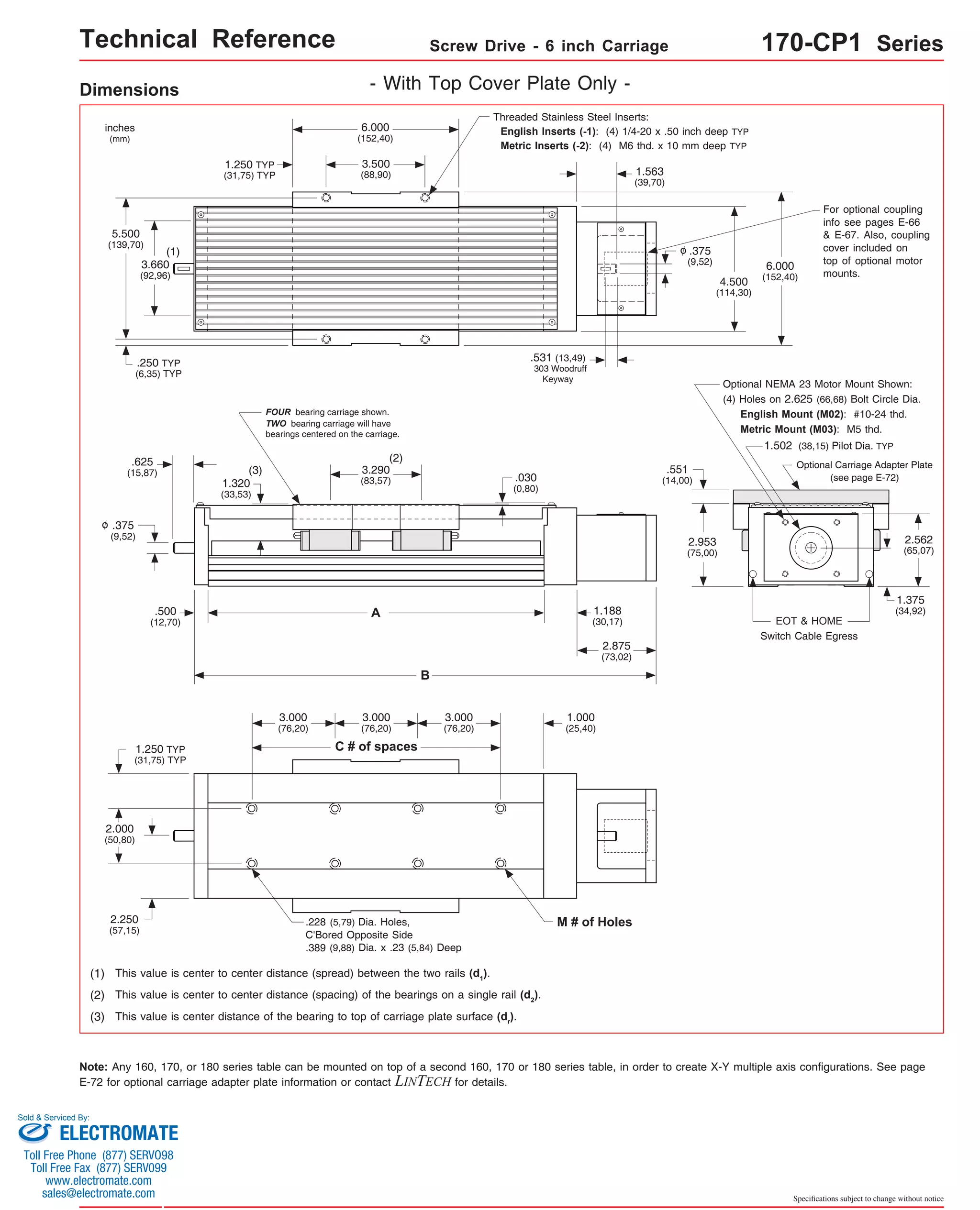
![Technical Reference Screw Drive - 6 inch Carriage 170-CP2 Series
Dimensions & Specifications
Travel
Length
Table Dimensions
Model
Number lbs
17x654-CP2 54
(1370)
Sold & Serviced By:
Specifications subject to change without notice
(kg)
inches
(mm)
C
inches
(mm)
Mounting Dimensions
17x606-CP2
inches
(mm)
A
B
16.688
(423,9)
Screw
Length
inches
(mm)
Table
Weight
12.125
(308,0)
18.125
(460,4)
24.125
(612,8)
30.125
(765,2)
36.125
(917,6)
42.125
(1070,0)
48.125
(1222,4)
54.125
(1374,8)
60.125
(1527,1)
66.125
(1679,6)
64.688
(1643,0)
19 40 (1625) 37.1
(16,8)
x = 2; Carriage has 2 bearings; Carriage weight = 2.5 lbs. (1,13 kg)
(1)
17x612-CP2
6
(150)
12
(300)
17x618-CP2 18
(455)
17x624-CP2 24
(605)
17x630-CP2 30
(760)
17x636-CP2 36
(910)
17x642-CP2 42
(1060)
17x648-CP2 48
(1215)
17x660-CP2 60
(1520)
- With Top & Side Cover Plates -
M
3 8
22.688
(576,3) 5 12
28.688
(728,7) 7 16
34.688
(881,1) 9 20
40.688
(1033,5) 11 24
46.688
(1185,9) 13 28
52.688
(1338,3) 15 32
58.688
(1490,7) 17 36
70.688
(1795,5) 21 44
x = 4; Carriage has 4 bearings; Carriage weight = 3.3 lbs. (1,50 kg)
16.6
(7,5)
19.1
(8,7)
21.7
(9,8)
24.3
(11,0)
26.8
(12,2)
29.4
(13,3)
32.0
(14,5)
34.5
(15,6)
39.6
(17,9)
16.00
(406)
22.00
(559)
28.00
(711)
34.00
(864)
40.00
(1016)
46.00
(1168)
52.00
(1321)
58.00
(1473)
64.00
70.00
(1778)
Footnotes:
(1) Weight shown is with a 0.625 inch (16 mm) diameter screw, a NEMA 23 motor mount [0.42 lbs (0,19 kg)], a C100 style [0.09 lbs (0,04 kg)] coupling, and
a 2 bearing carriage. When using a 0.750 inch (20 mm) diameter screw add 0.042 lbs per inch (0,00075 kg per mm) of screw length for a given model
number. When using a 4 bearing carriage add 0.8 lbs (0,36 kg) to each value.
ELECTROMATE
Toll Free Phone (877) SERVO98
Toll Free Fax (877) SERV099
www.electromate.com
sales@electromate.com](https://image.slidesharecdn.com/lintechpositioningsystemscatalog-141018113223-conversion-gate01/75/Lintech-positioning-systems_catalog-197-2048.jpg)
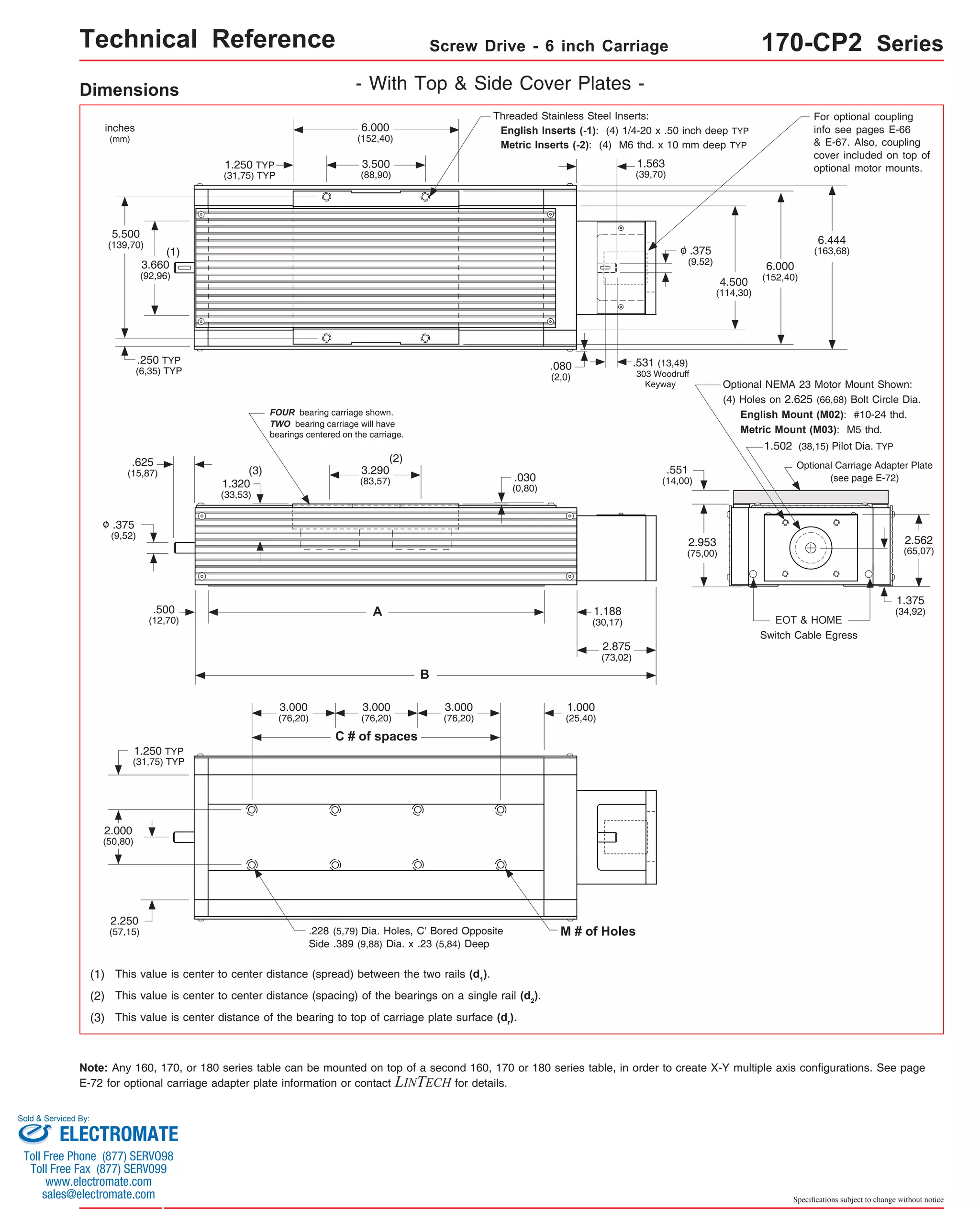
![Technical Reference Screw Drive - 6 inch Carriage 170-WC1 Series
Dimensions & Specifications
Travel
Length
Table Dimensions
Model
Number lbs
17x641-WC1 41.5
(1050)
Sold & Serviced By:
Specifications subject to change without notice
(kg)
inches
(mm)
C
inches
(mm)
Mounting Dimensions
17x603-WC1
inches
(mm)
A
B
16.688
(423,9)
Screw
Length
inches
(mm)
Table
Weight
12.125
(308,0)
18.125
(460,4)
24.125
(612,8)
30.125
(765,2)
36.125
(917,6)
42.125
(1070,0)
48.125
(1222,4)
54.125
(1374,8)
60.125
(1527,1)
66.125
(1679,6)
64.688
(1643,0)
19 40 (1625) 30.8
(14,0)
x = 2; Carriage has 2 bearings; Carriage weight = 2.5 lbs. (1,13 kg)
(1)
17x608-WC1
3.7
(94)
8.0
(203)
17x612-WC1 12.8
(325)
17x617-WC1 17.5
(444)
17x622-WC1 22.0
(555)
17x628-WC1 28.0
(710)
17x632-WC1 32.5
(825)
17x637-WC1 37.0
(935)
17x647-WC1 47.5
(1205)
- With Waycovers -
M
3 8
22.688
(576,3) 5 12
28.688
(728,7) 7 16
34.688
(881,1) 9 20
40.688
(1033,5) 11 24
46.688
(1185,9) 13 28
52.688
(1338,3) 15 32
58.688
(1490,7) 17 36
70.688
(1795,5) 21 44
x = 4; Carriage has 4 bearings; Carriage weight = 3.3 lbs. (1,50 kg)
14.8
(6,7)
16.8
(7,6)
18.8
(8,5)
20.9
(9,5)
22.7
(10,3)
24.7
(11,2)
26.7
(12,1)
28.7
(13,0)
33.0
(15,0)
16.00
(406)
22.00
(559)
28.00
(711)
34.00
(864)
40.00
(1016)
46.00
(1168)
52.00
(1321)
58.00
(1473)
64.00
70.00
(1778)
Footnotes:
(1) Weight shown is with a 0.625 inch (16 mm) diameter screw, a NEMA 23 motor mount [0.42 lbs (0,19 kg)], a C100 style [0.09 lbs (0,04 kg)] coupling, and
a 2 bearing carriage. When using a 0.750 inch (20 mm) diameter screw add 0.042 lbs per inch (0,00075 kg per mm) of screw length for a given model
number. When using a 4 bearing carriage add 0.8 lbs (0,36 kg) to each value.
ELECTROMATE
Toll Free Phone (877) SERVO98
Toll Free Fax (877) SERV099
www.electromate.com
sales@electromate.com](https://image.slidesharecdn.com/lintechpositioningsystemscatalog-141018113223-conversion-gate01/75/Lintech-positioning-systems_catalog-199-2048.jpg)
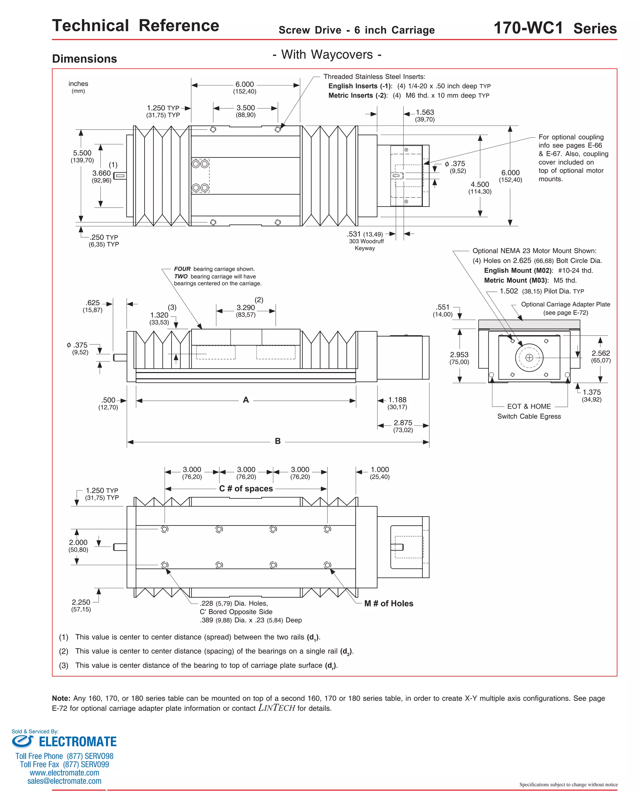
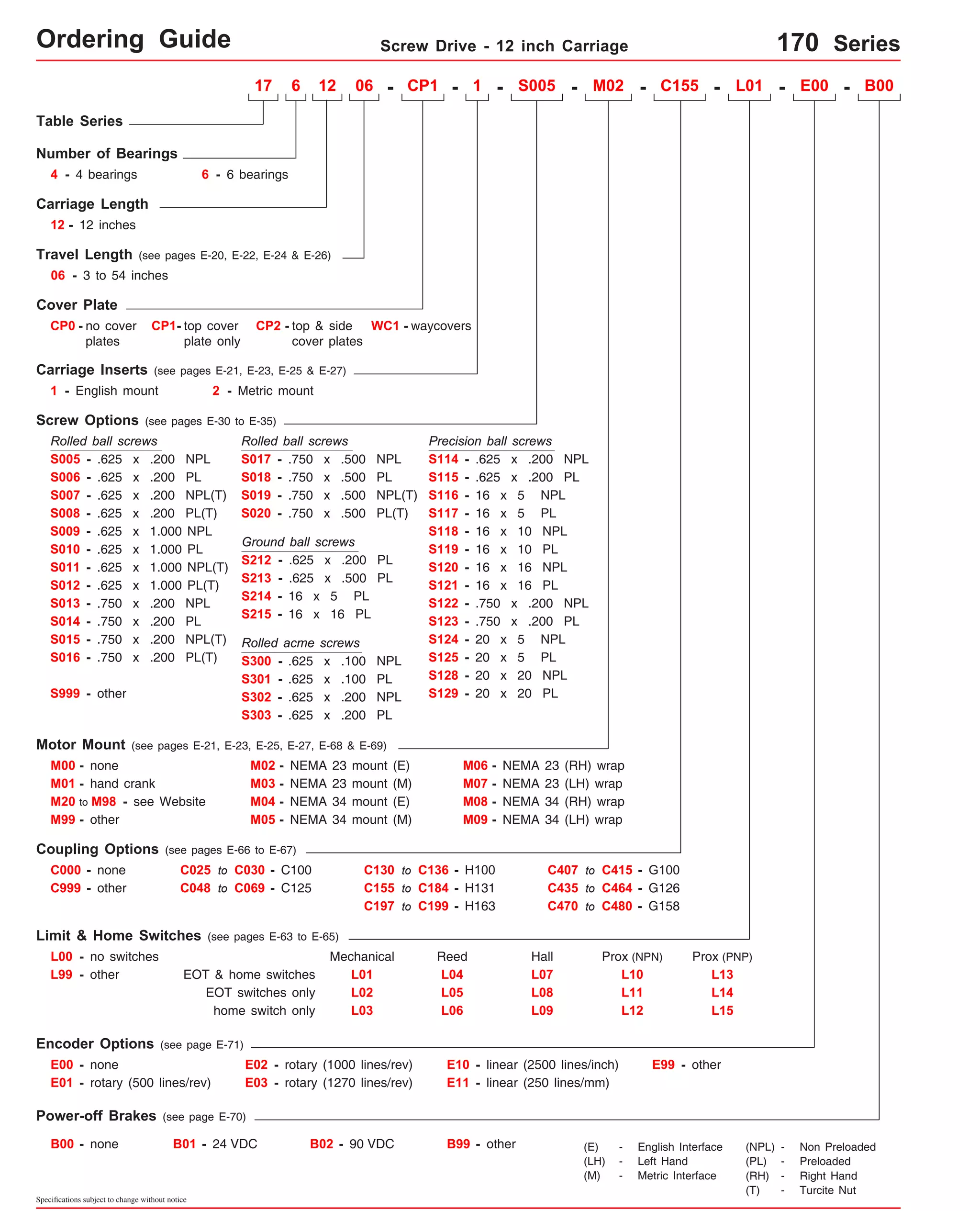

![Technical Reference Screw Drive - 12 inch Carriage 170-CP0 Series
Dimensions & Specifications
Travel
Length
Table Dimensions
Model
Number lbs
17x1248-CP0 48
22.00
(559)
28.00
(711)
34.00
(864)
40.00
(1016)
46.00
(1168)
52.00
(1321)
58.00
(1473)
18.125
(460,4)
24.125
(612,8)
30.125
(765,2)
36.125
(917,6)
42.125
(1070,0)
48.125
(1222,4)
54.125
(1374,8)
64.688
(1643,1)
64.00
(1626)
60.125
(1527,2)
(1215) 19 40 31.2
(14,2)
17x1254-CP0 54
(1370)
70.688
21 44 70.00
33.0
(1795,5) (1778)
(15,0)
66.125
(1679,6)
Sold & Serviced By:
Specifications subject to change without notice
(kgf)
inches
(mm)
C
inches
(mm)
Mounting Dimensions
17x1206-CP0
inches
(mm)
A
B
Screw
Length
inches
(mm)
Table
Weight
x = 4; Carriage has 4 bearings; Carriage weight = 5.0 lbs. (2,27 kg)
x = 6; Carriage has 6 bearings; Carriage weight = 5.8 lbs. (2,63 kg)
(1)
17x1212-CP0
6
(150)
17x1218-CP0
12
(300)
17x1224-CP0
18
(455)
17x1230-CP0
24
(605)
17x1236-CP0
30
(760)
17x1242-CP0
36
(910)
42
(1060)
- Without Cover Plates -
M
22.688
(576,3) 5 12
28.688
(728,7) 7 16
34.688
(881,1) 9 20
40.688
(1033,5) 11 24
46.688
(1185,9) 13 28
52.688
(1338,3) 15 32
58.688
(1490,7) 17 36
18.5
(8,4)
20.3
(9,2)
22.1
(10,2)
23.9
(10,8)
25.7
(11,7)
27.5
(12,5)
29.3
(13,3)
Footnotes:
(1) Weight shown is with a 0.625 inch (16 mm) diameter screw, a NEMA 23 motor mount [0.42 lbs (0,19 kg)], a C100 style [0.09 lbs (0,04 kg)] coupling, and
a 4 bearing carriage. When using a 0.750 inch (20 mm) diameter screw add 0.042 lbs per inch (0,00075 kg per mm) of screw length for a given model
number. When using a 6 bearing carriage add 0.8 lbs (0,36 kg) to each value.
ELECTROMATE
Toll Free Phone (877) SERVO98
Toll Free Fax (877) SERV099
www.electromate.com
sales@electromate.com](https://image.slidesharecdn.com/lintechpositioningsystemscatalog-141018113223-conversion-gate01/75/Lintech-positioning-systems_catalog-203-2048.jpg)
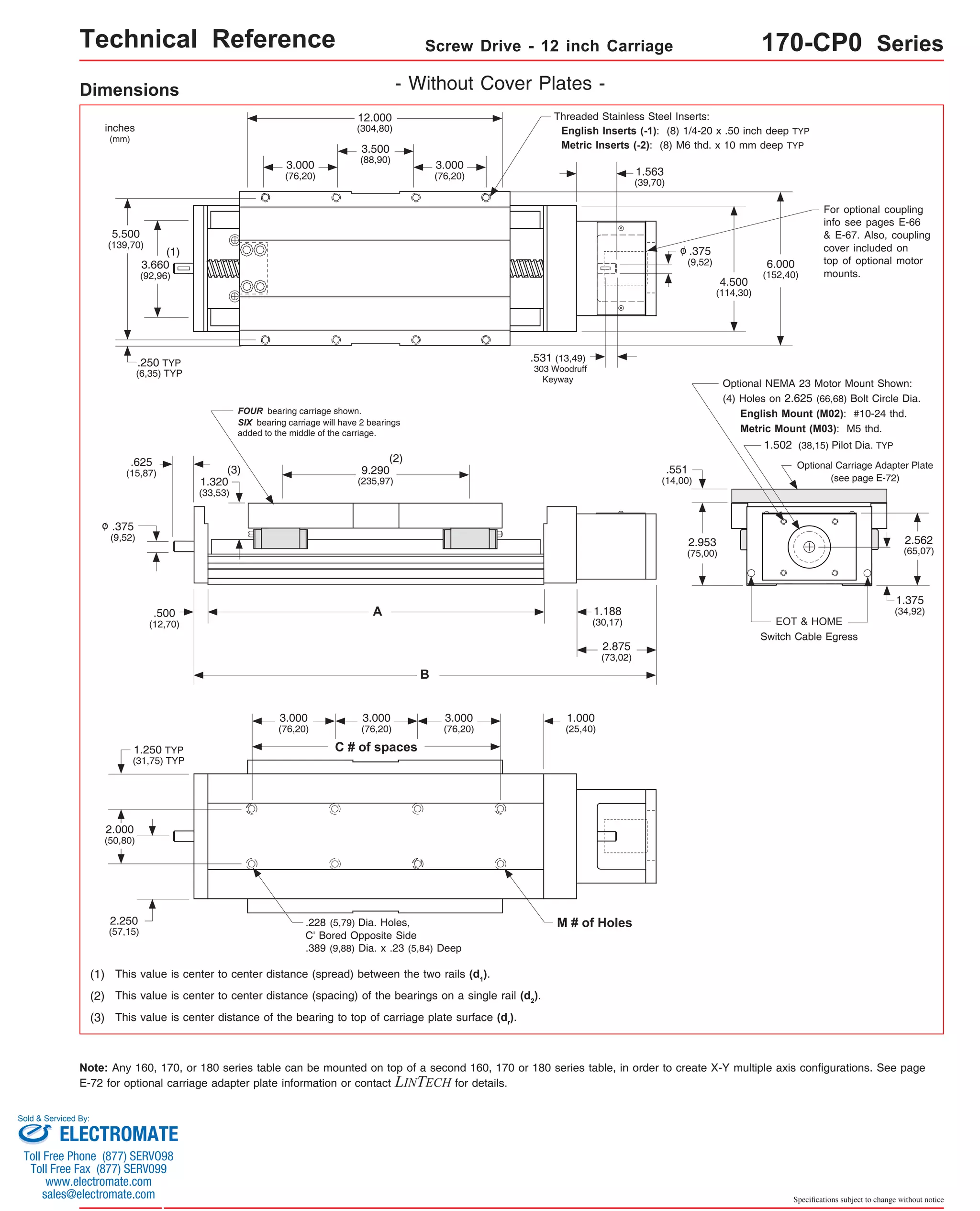
![Technical Reference Screw Drive - 12 inch Carriage 170-CP1 Series
Mounting Dimensions
inches
(mm)
Dimensions & Specifications
Table Dimensions
inches
(mm)
Travel
Length
Screw
Length
inches
(mm)
Table
Weight
Model
Number lbs
inches
(mm)
6
(150)
12
(300)
18
(455)
24
(605)
30
(760)
17x1206-CP1
17x1212-CP1
17x1218-CP1
17x1224-CP1
17x1230-CP1
17x1236-CP1
17x1242-CP1
36
(910)
42
(1060)
17x1248-CP1 48
C
A
B
M
22.688
(576,3) 5 12
28.688
(728,7) 7 16
34.688
(881,1) 9 20
40.688
(1033,5) 11 24
46.688
(1185,9) 13 28
52.688
(1338,3) 15 32
58.688
(1490,7) 17 36
18.125
(460,4)
24.125
(612,8)
30.125
(765,2)
36.125
(917,6)
42.125
(1070,0)
48.125
(1222,4)
54.125
(1374,8)
64.688
(1643,1)
60.125
(1527,2)
(1215) 19 40
17x1254-CP1 54
(1370)
x = 4; Carriage has 4 bearings; Carriage weight = 5.0 lbs. (2,27 kg)
x = 6; Carriage has 6 bearings; Carriage weight = 5.8 lbs. (2,63 kg)
Sold & Serviced By:
Specifications subject to change without notice
- With Top Cover Plate Only -
(kgf)
19.7
(8,9)
21.9
(9,9)
24.1
(10,9)
26.3
(11,9)
28.5
(12,9)
30.7
(13,9)
32.9
(14,9)
35.1
(15,9)
22.00
(559)
28.00
(711)
34.00
(864)
40.00
(1016)
46.00
(1168)
52.00
(1321)
58.00
(1473)
64.00
(1626)
70.688
(1795,5) 21 44 70.00
(1778)
66.125
(1679,6)
(1)
37.3
(16,9)
Footnotes:
(1) Weight shown is with a 0.625 inch (16 mm) diameter screw, a NEMA 23 motor mount [0.42 lbs (0,19 kg)], a C100 style [0.09 lbs (0,04 kg)] coupling, and
a 4 bearing carriage. When using a 0.750 inch (20 mm) diameter screw add 0.042 lbs per inch (0,00075 kg per mm) of screw length for a given model
number. When using a 6 bearing carriage add 0.8 lbs (0,36 kg) to each value.
ELECTROMATE
Toll Free Phone (877) SERVO98
Toll Free Fax (877) SERV099
www.electromate.com
sales@electromate.com](https://image.slidesharecdn.com/lintechpositioningsystemscatalog-141018113223-conversion-gate01/75/Lintech-positioning-systems_catalog-205-2048.jpg)
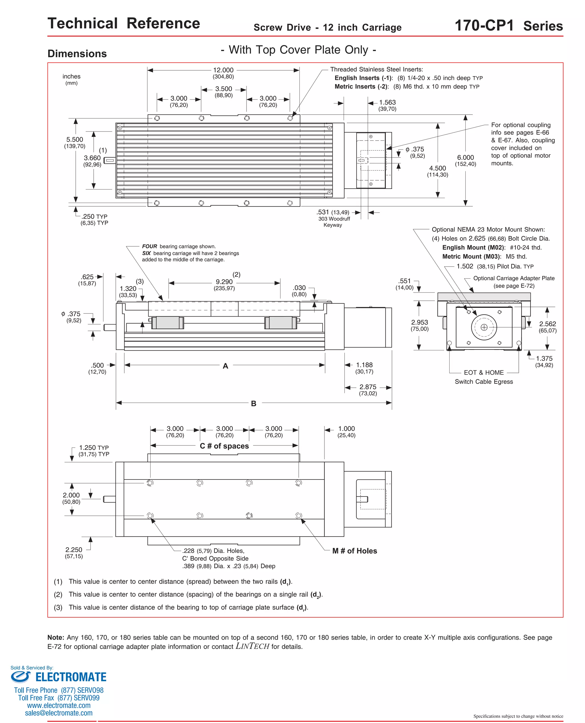
![Technical Reference Screw Drive - 12 inch Carriage 170-CP2 Series
Mounting Dimensions
inches
(mm)
Dimensions & Specifications
Table Dimensions
inches
(mm)
Travel
Length
Screw
Length
inches
(mm)
Table
Weight
Model
Number lbs
17x1206-CP2
inches
(mm)
17x1212-CP2
6
(150)
17x1218-CP2
12
(300)
17x1224-CP2
18
(455)
17x1230-CP2
24
(605)
17x1236-CP2
30
(760)
17x1242-CP2
36
(910)
42
(1060)
17x1248-CP2 48
C
A
B
M
22.688
(576,3) 5 12
28.688
(728,7) 7 16
34.688
(881,1) 9 20
40.688
(1033,5) 11 24
46.688
(1185,9) 13 28
52.688
(1338,3) 15 32
58.688
(1490,7) 17 36
18.125
(460,4)
24.125
(612,8)
30.125
(765,2)
36.125
(917,6)
42.125
(1070,0)
48.125
(1222,4)
54.125
(1374,8)
64.688
(1643,1)
60.125
(1527,2)
(1215) 19 40
17x1254-CP2 54
(1370)
x = 4; Carriage has 4 bearings; Carriage weight = 5.0 lbs. (2,27 kg)
x = 6; Carriage has 6 bearings; Carriage weight = 5.8 lbs. (2,63 kg)
Sold & Serviced By:
Specifications subject to change without notice
- With Top & Side Cover Plates -
(kgf)
21.6
(9,8)
24.2
(11,0)
26.1
(11,8)
28.7
(13,1)
31.3
(14,2)
34.5
(15,7)
37.0
(16,8)
39.6
(18,0)
22.00
(559)
28.00
(711)
34.00
(864)
40.00
(1016)
46.00
(1168)
52.00
(1321)
58.00
(1473)
64.00
(1626)
70.688
(1795,5) 21 44 70.00
(1778)
66.125
(1679,6)
(1)
42.1
(19,1)
Footnotes:
(1) Weight shown is with a 0.625 inch (16 mm) diameter screw, a NEMA 23 motor mount [0.42 lbs (0,19 kg)], a C100 style [0.09 lbs (0,04 kg)] coupling, and
a 4 bearing carriage. When using a 0.750 inch (20 mm) diameter screw add 0.042 lbs per inch (0,00075 kg per mm) of screw length for a given model
number. When using a 6 bearing carriage add 0.8 lbs (0,36 kg) to each value.
ELECTROMATE
Toll Free Phone (877) SERVO98
Toll Free Fax (877) SERV099
www.electromate.com
sales@electromate.com](https://image.slidesharecdn.com/lintechpositioningsystemscatalog-141018113223-conversion-gate01/75/Lintech-positioning-systems_catalog-207-2048.jpg)
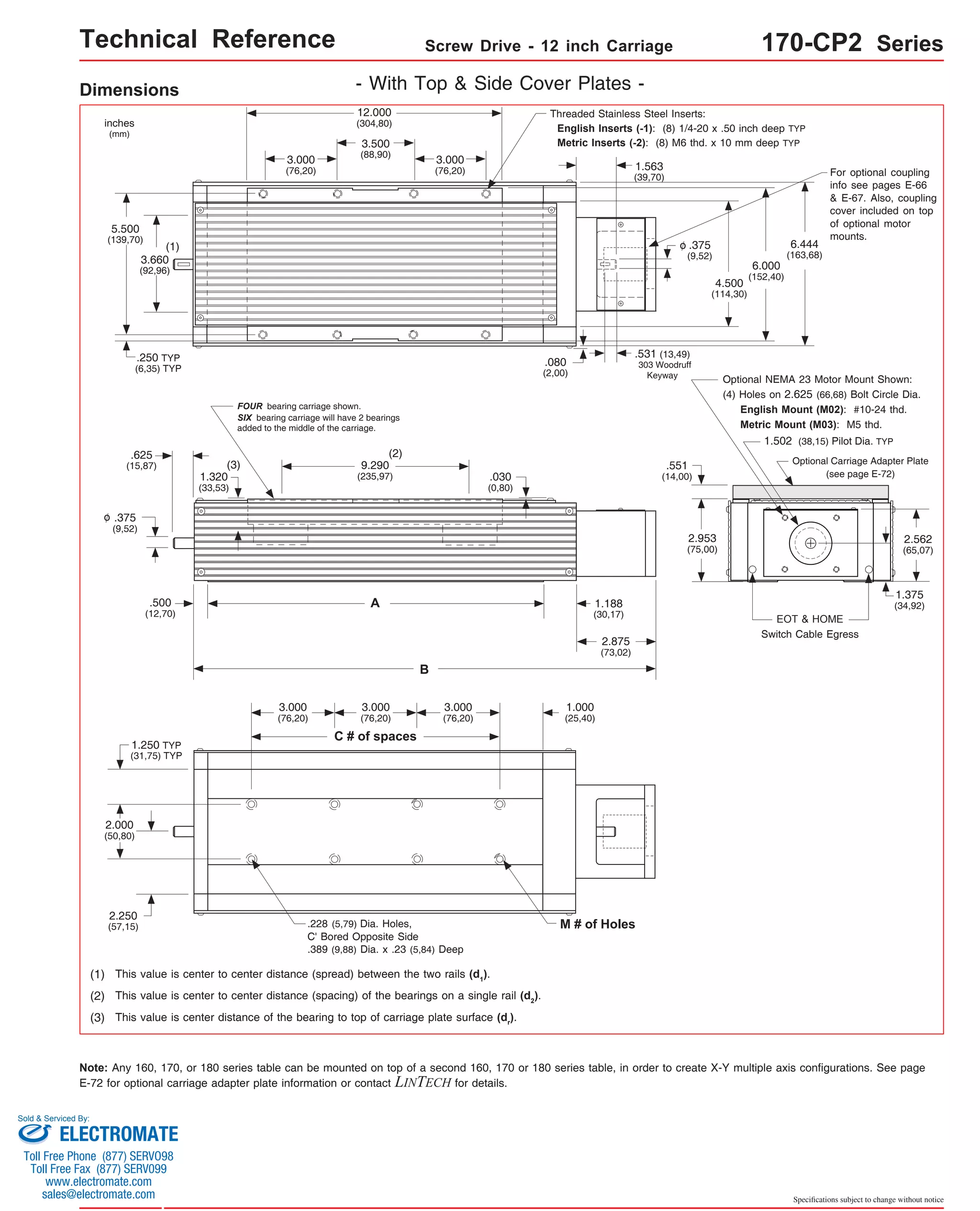
![Technical Reference Screw Drive - 12 inch Carriage 170-WC1 Series
Travel
Length
Table Dimensions
Model
Number lbs
17x1203-WC1 3.7
(94)
17x1208-WC1 8.0
(203)
17x1212-WC1 12.8
(444)
17x1217-WC1 17.5
(597)
17x1222-WC1 22.0
(555)
17x1228-WC1 28.0
(710)
17x1232-WC1 32.5
(825)
17x1237-WC1 37.0
(935)
17x1241-WC1 41.5
(1050)
64.688
(1643,1) 21 44 30.9
(14,0)
60.125
(1527,2)
x = 4; Carriage has 4 bearings; Carriage weight = 5.0 lbs. (2,27 kg)
x = 6; Carriage has 6 bearings; Carriage weight = 5.8 lbs. (2,63 kg)
Sold & Serviced By:
Specifications subject to change without notice
(kg)
inches
(mm)
C
inches
(mm)
Mounting Dimensions
inches
(mm)
A
B
Screw
Length
inches
(mm)
Table
Weight
(1)
Dimensions & Specifications - With Waycovers -
M
22.688
(576,3) 5 12
28.688
(728,7) 7 16
34.688
(881,1) 9 20
40.688
(1033,5) 11 24
46.688
(1185,9) 13 28
52.688
(1338,3) 15 32
58.688
(1490,7) 17 36
70.688
(1795,5) 21 44
16.8
(7,6)
18.8
(8,5)
20.9
(9,5)
22.7
(10,3)
24.7
(11,2)
26.7
(12,1)
28.7
(13,0)
33.0
(15,0)
22.00
(559)
28.00
(711)
34.00
(864)
40.00
(1016)
46.00
(1168)
52.00
(1321)
58.00
(1473)
64.00
(1626)
70.00
(1778)
18.125
(460,4)
24.125
(612,8)
30.125
(765,2)
36.125
(917,6)
42.125
(1070,0)
48.125
(1222,4)
54.125
(1374,8)
66.125
(1679,6)
Footnotes:
(1) Weight shown is with a 0.625 inch (16 mm) diameter screw, a NEMA 23 motor mount [0.42 lbs (0,19 kg)], a C100 style [0.09 lbs (0,04 kg)] coupling, and
a 2 bearing carriage. When using a 0.750 inch (20 mm) diameter screw add 0.042 lbs per inch (0,00075 kg per mm) of screw length for a given model
number. When using a 4 bearing carriage add 0.8 lbs (0,36 kg) to each value.
ELECTROMATE
Toll Free Phone (877) SERVO98
Toll Free Fax (877) SERV099
www.electromate.com
sales@electromate.com](https://image.slidesharecdn.com/lintechpositioningsystemscatalog-141018113223-conversion-gate01/75/Lintech-positioning-systems_catalog-209-2048.jpg)
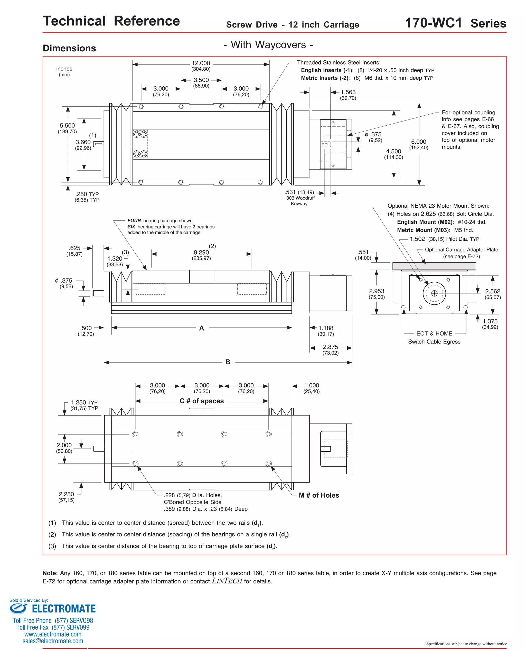
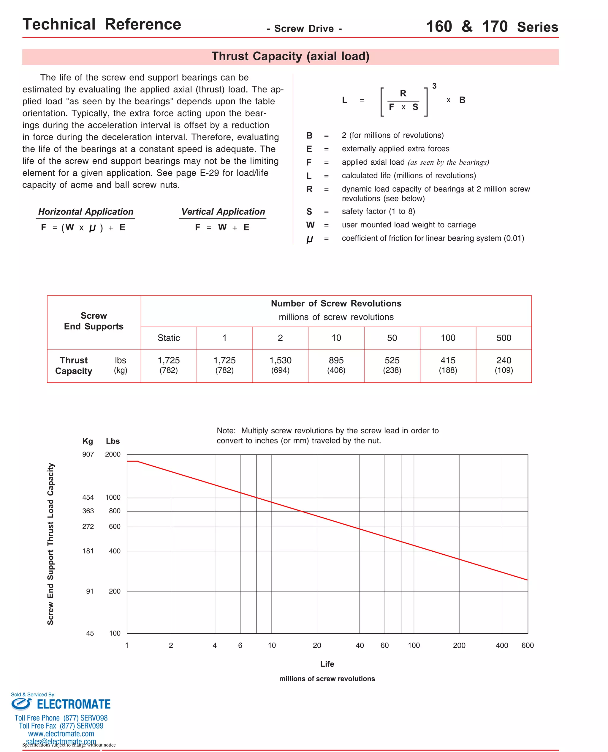
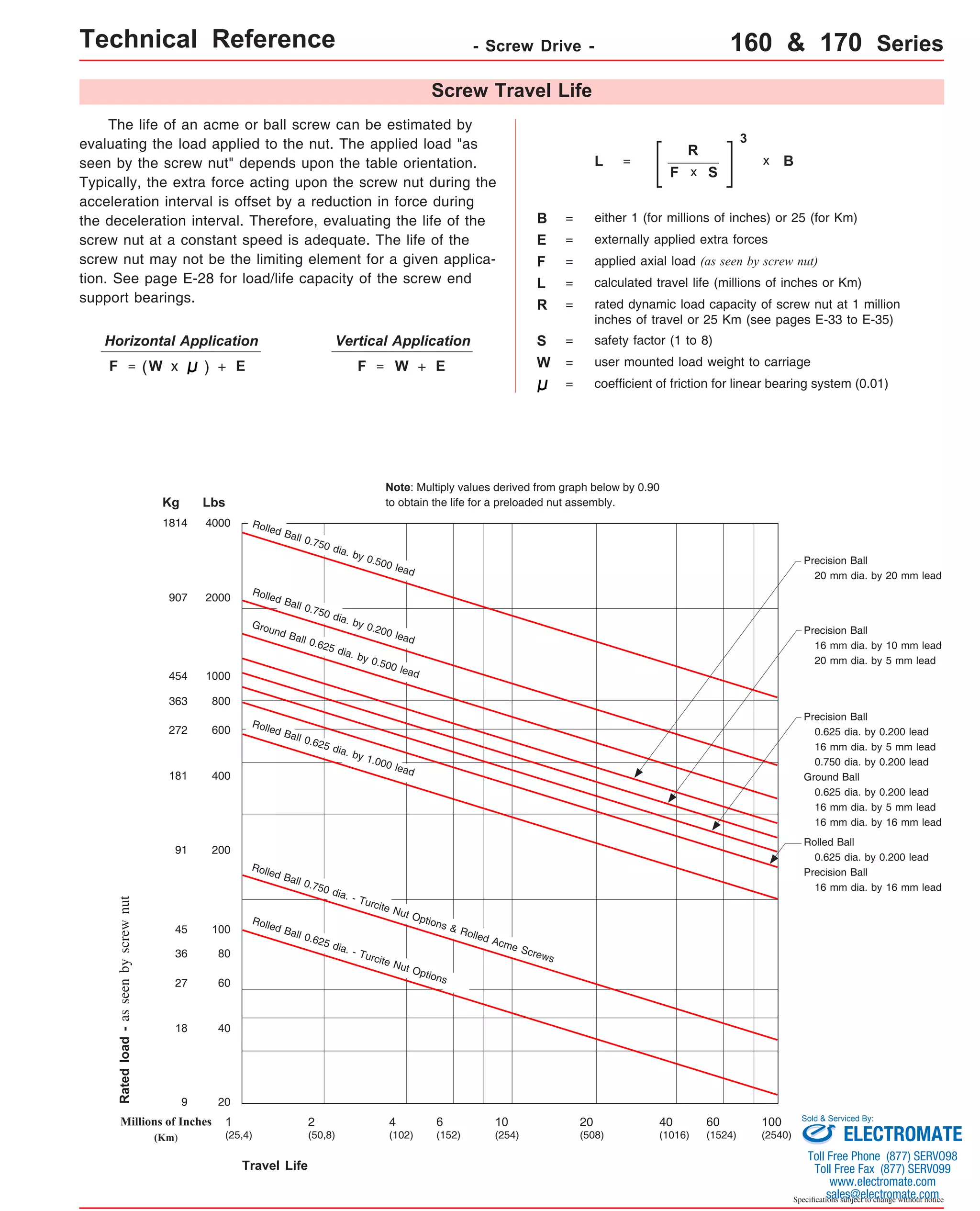
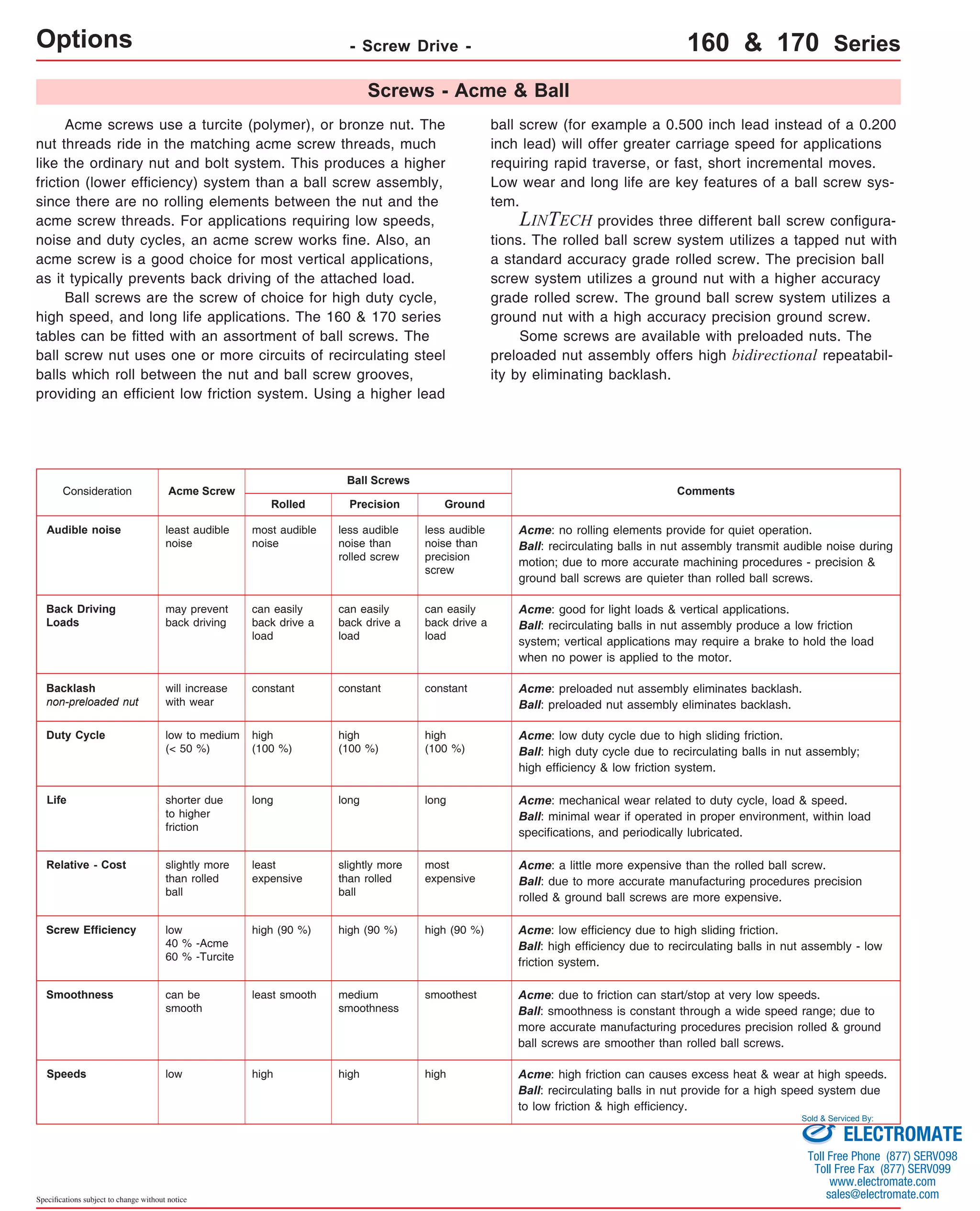
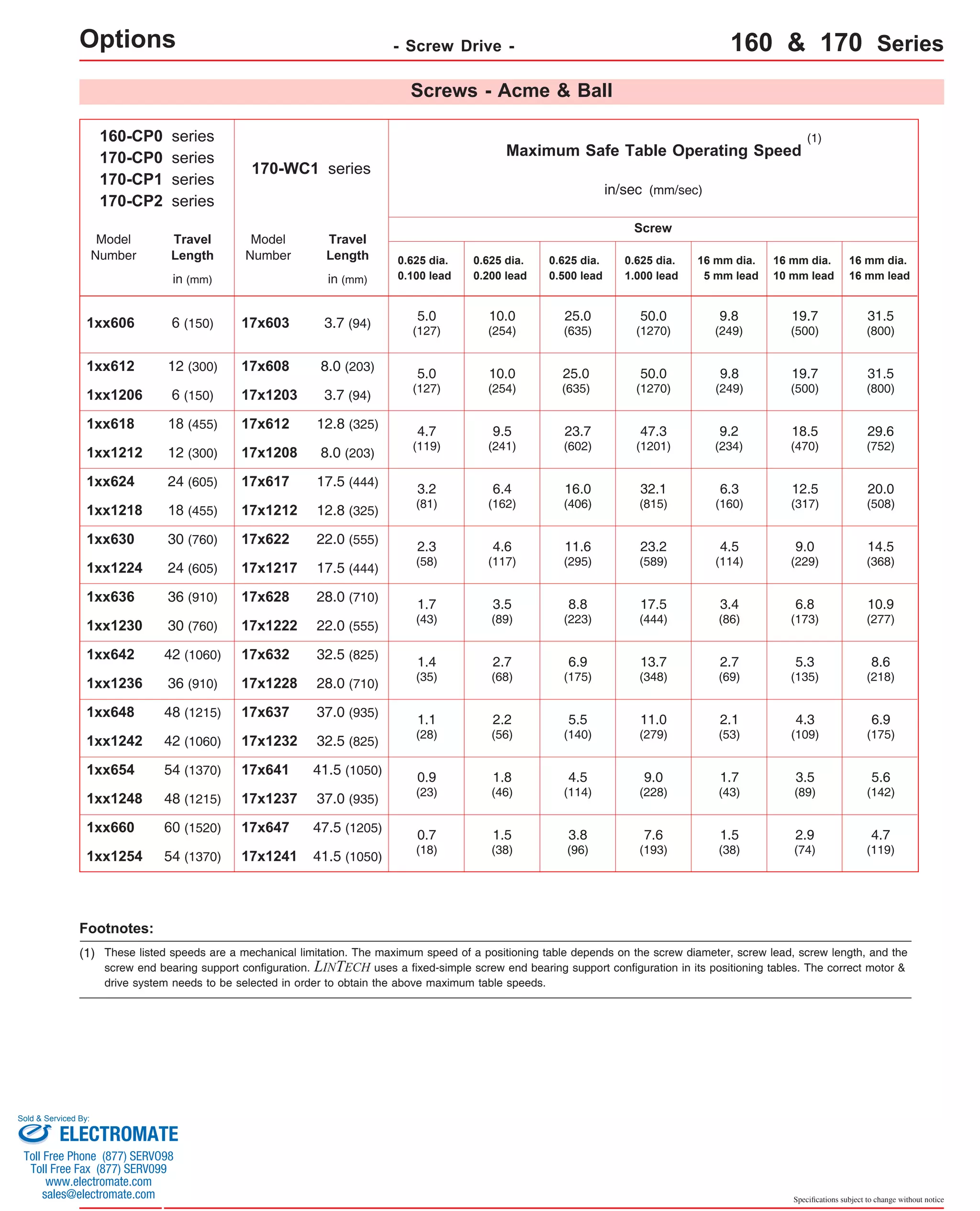
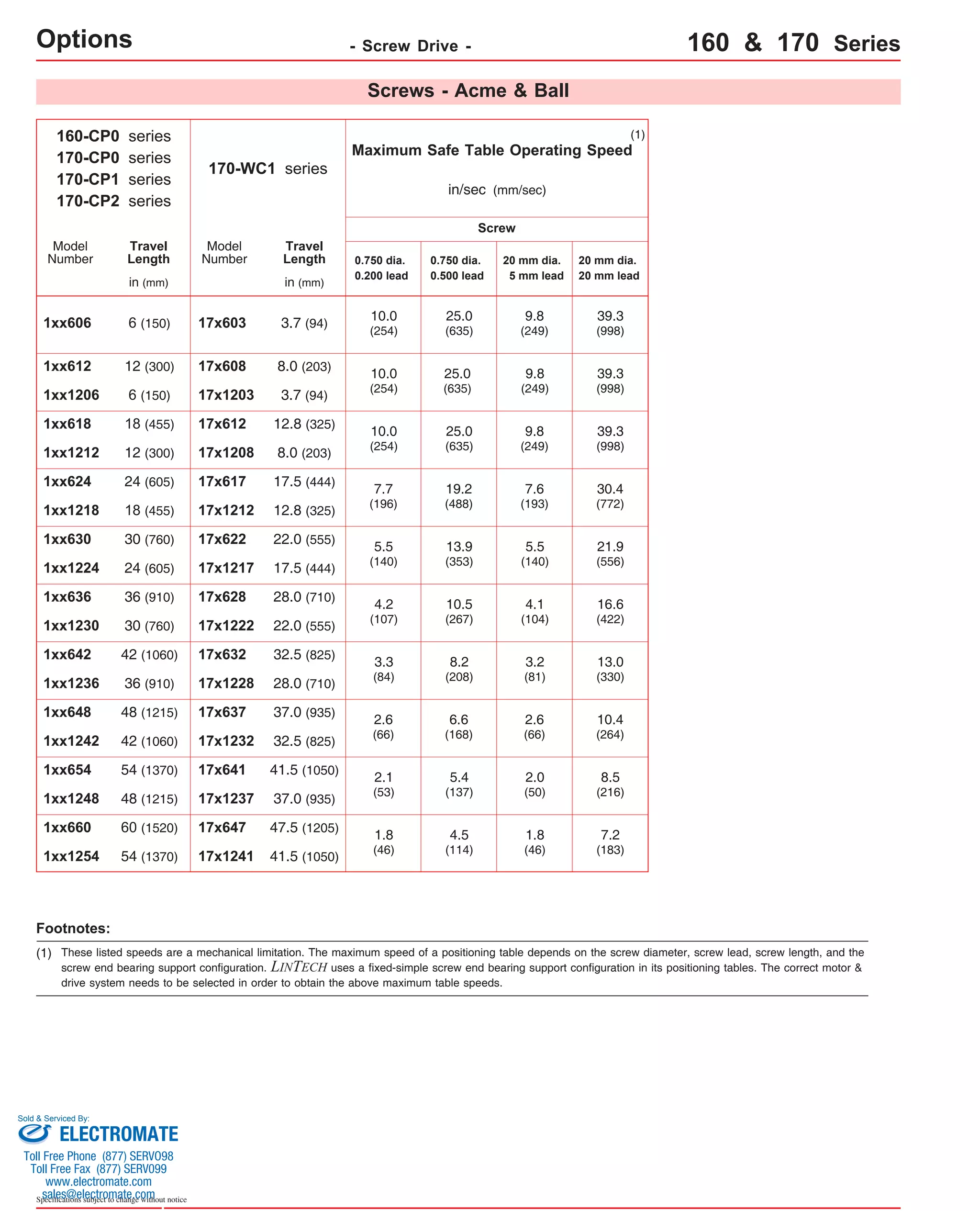

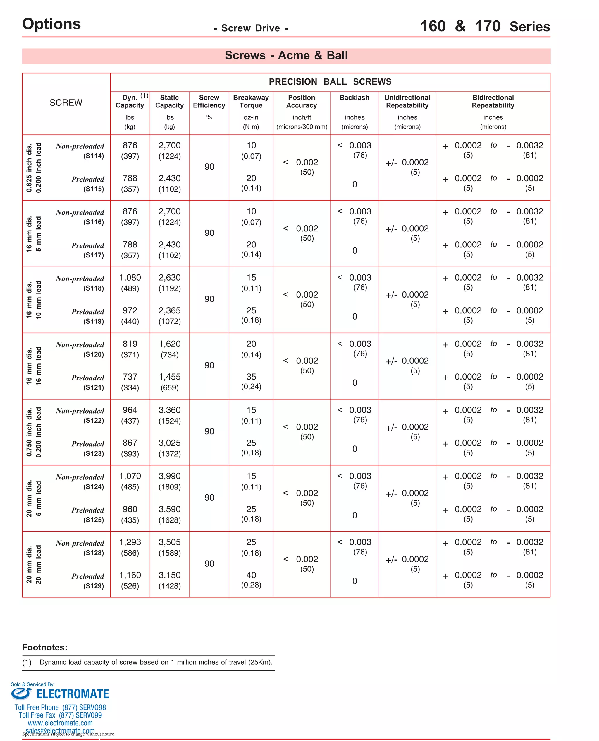
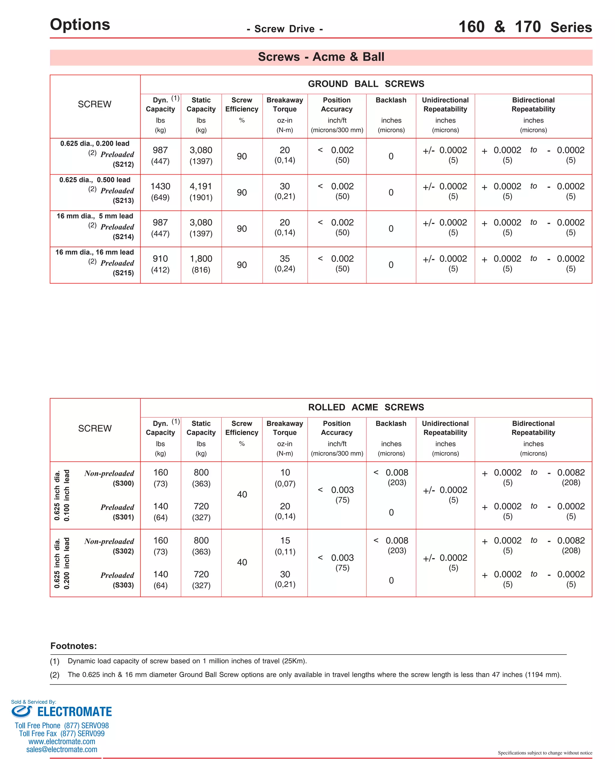

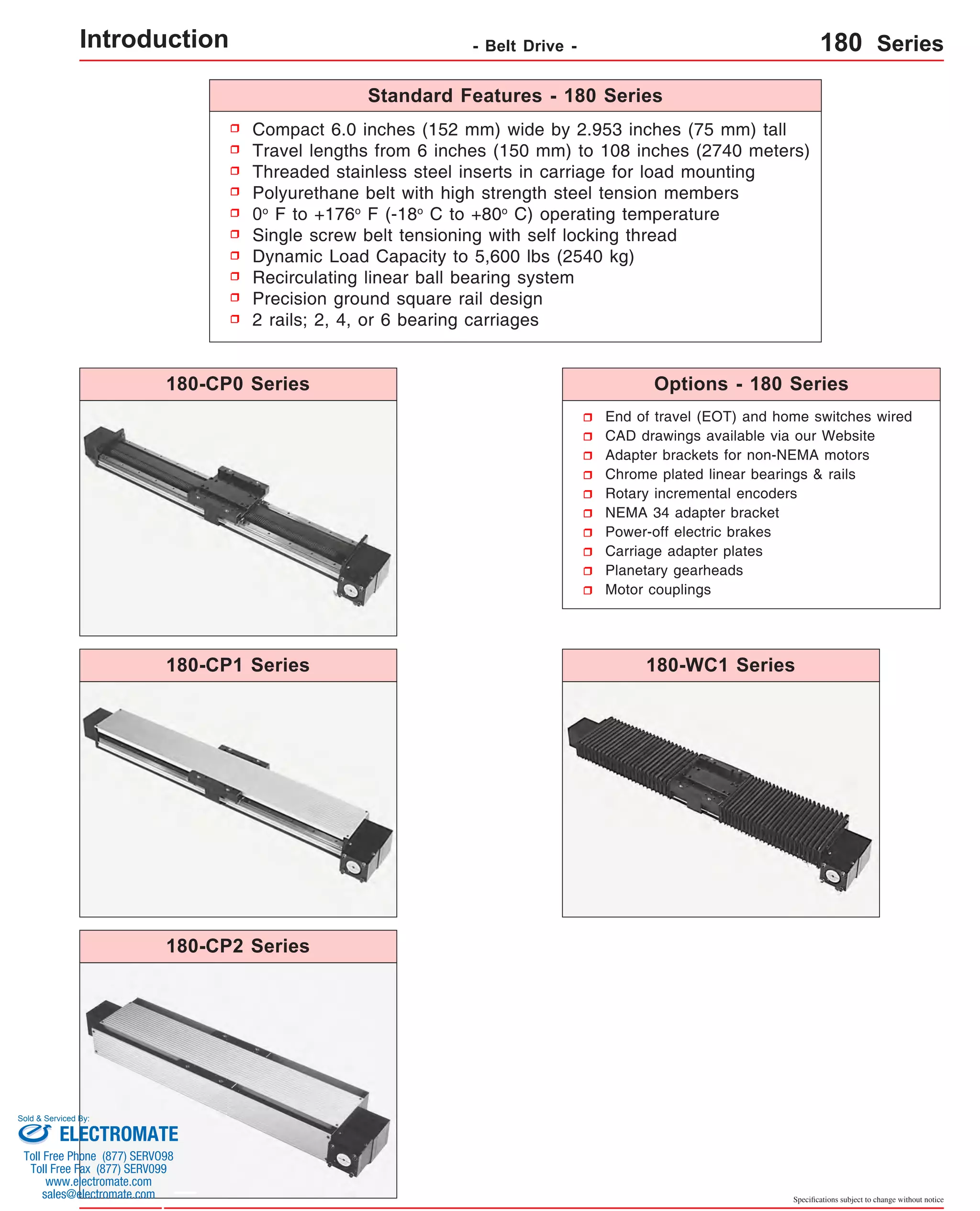
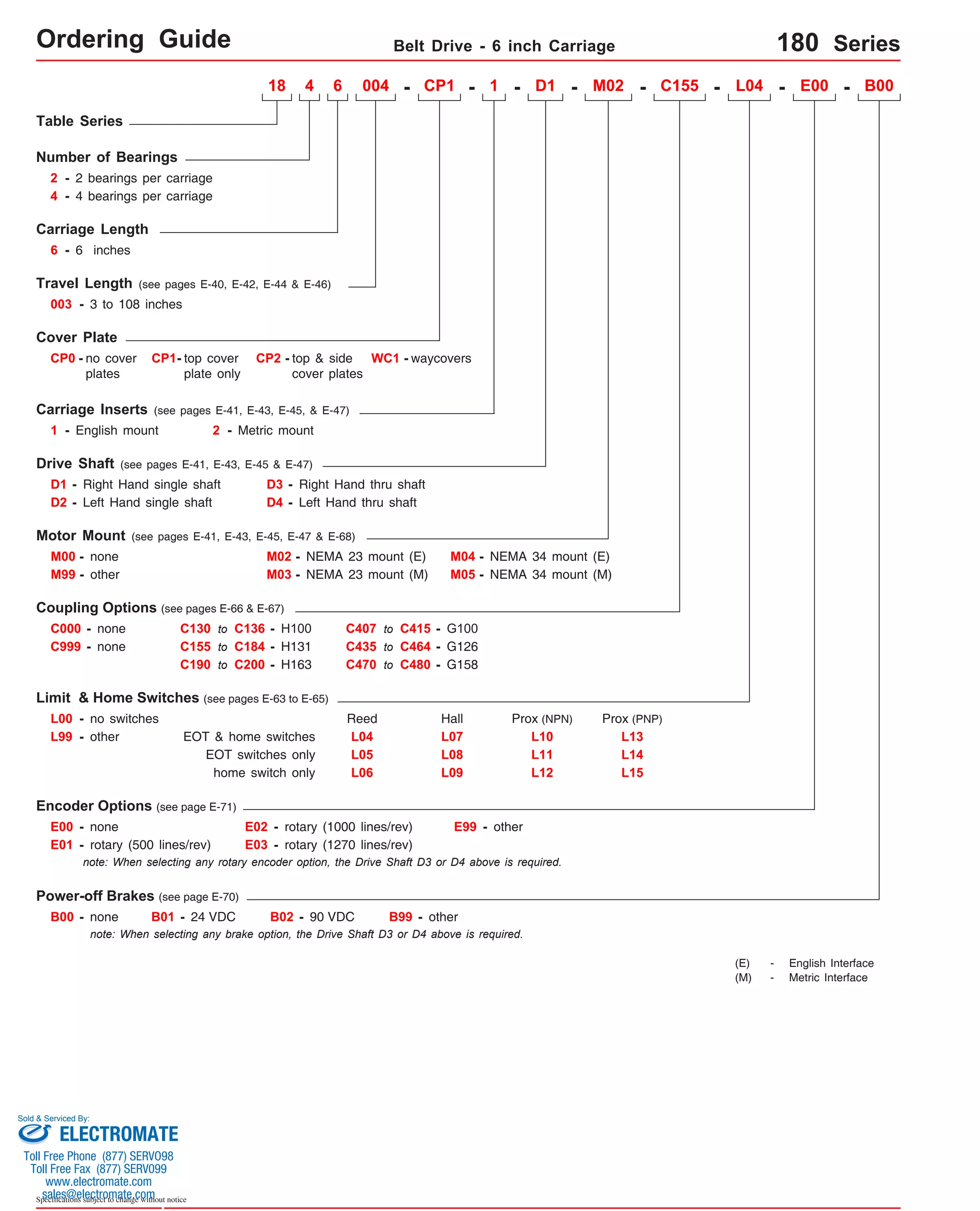
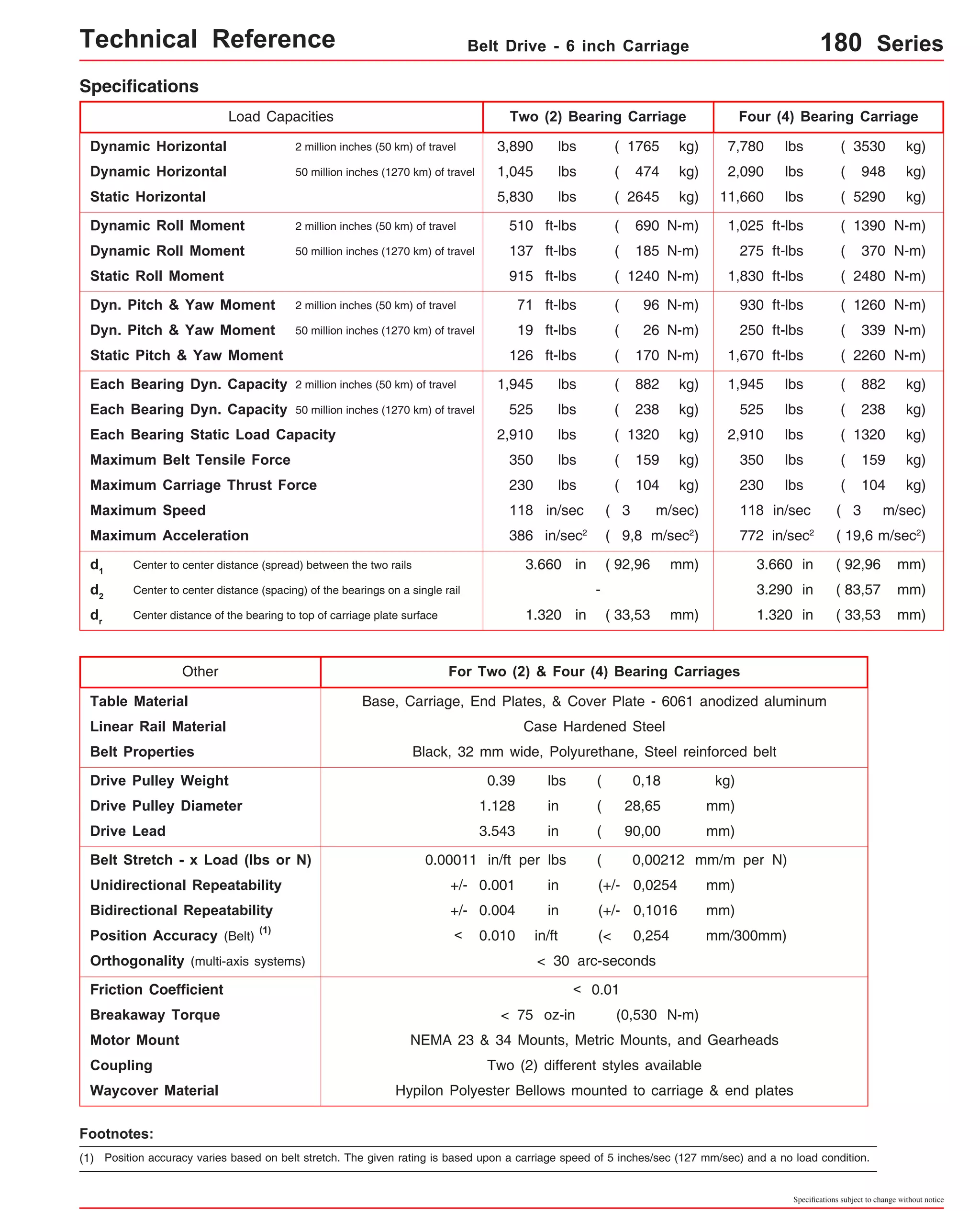
![Technical Reference Belt Drive - 6 inch Carriage 180-CP0 Series
Dimensions & Specifications
Travel
Length
Table Dimensions
Model
Number lbs
18x6054-CP0 54
(1370)
18x6072-CP0 72
(1825)
18x6084-CP0 84
(2130)
18x6096-CP0 96
(2435)
18x6108-CP0 108
(2740)
Sold & Serviced By:
Specifications subject to change without notice
(kg)
inches
(mm)
C
inches
(mm)
Mounting Dimensions
18x6006-CP0
inches
(mm)
A
B
18.250
(463,6)
Belt
Weight
ounces
(kg)
Table
Weight
3.8
(0,11)
(1)
18x6012-CP0
6
(150)
12
(300)
18x6018-CP0 18
(455)
18x6024-CP0 24
(605)
18x6030-CP0 30
(760)
18x6036-CP0 36
(910)
18x6042-CP0 42
(1060)
18x6048-CP0 48
(1215)
18x6060-CP0 60
(1520)
- Without Cover Plates -
M
3 8
24.250
(616,0)
5.3
5 12 (0,15)
30.250
(768,4)
6.8
7 16 (0,19)
36.250
(920,8)
8.3
9 20 (0,23)
42.250
(1073,2)
9.8
11 24 (0,28)
48.250
(1225,6)
11.3
13 28 (0,32)
54.250
(1378,0)
12.8
15 32 (0,36)
60.250
(1530,4)
14.3
17 36 (0,41)
66.250
(1682,7)
72.250
(1835,2)
17.3
21 44 (0,49)
17.4
(7,9)
19.6
(8,9)
21.8
(9,9)
24.0
(10,9)
26.2
(11,9)
28.4
(12,9)
30.6
(13,9)
32.8
(14,9)
37.2
(16,9)
12.125
(308,0)
18.125
(460,4)
24.125
(612,8)
30.125
(765,2)
36.125
(917,6)
42.125
(1070,0)
48.125
(1222,4)
54.125
(1374,8)
66.125
(1679,6)
78.125
(1984,4)
84.250
(2140,0)
x = 2; Carriage has 2 bearings; Carriage weight = 2.5 lbs. (1,13 kg)
x = 4; Carriage has 4 bearings; Carriage weight = 3.3 lbs. (1,50 kg)
20.3
25 52 (0,58)
90.125
(2289,2)
96.250
(2444,8)
23.3
29 60 (0,66)
102.125
(2594,0)
108.250
(2749,6)
26.3
33 68 (0,75)
114.125
(2898,8)
120.250
(3054,4)
29.3
37 76 (0,83)
41.6
(18,9)
46.0
(20,9)
50.4
(22,9)
54.8
(24,9)
Footnotes:
(1) Weight shown is with a 2 bearing carriage [2.5 lbs (1,13 kg)], a NEMA 23 motor mount [0.39 lbs (0,18 kg)], and a H100 style [0.08 lbs (0,04 kg)] coupling.
When using a 4 bearing carriage add 0.8 lbs (0,36 kg) to each value.
15.8
19 40 (0,45) 35.0
(15,9)
60.125
(1527,1)
version: 01/2014
ELECTROMATE
Toll Free Phone (877) SERVO98
Toll Free Fax (877) SERV099
www.electromate.com
sales@electromate.com](https://image.slidesharecdn.com/lintechpositioningsystemscatalog-141018113223-conversion-gate01/75/Lintech-positioning-systems_catalog-223-2048.jpg)
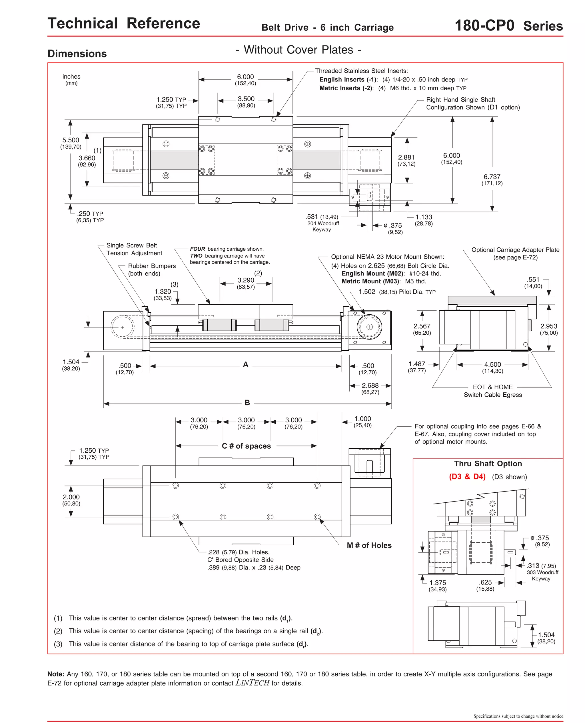
![Technical Reference Belt Drive - 6 inch Carriage 180-CP1 Series
Dimensions & Specifications
Travel
Length
Table Dimensions
(1)
Model
Number lbs
18x6054-CP1 54
(1370)
Sold & Serviced By:
Specifications subject to change without notice
(kg)
inches
(mm)
C
inches
(mm)
Mounting Dimensions
18x6006-CP1
inches
(mm)
A
B
18.250
(463,6)
Belt
Weight
ounces
(kg)
Table
Weight
3.8
(0,11)
(2)
18x6012-CP1
6
(150)
12
(300)
18x6018-CP1 18
(455)
18x6024-CP1 24
(605)
18x6030-CP1 30
(760)
18x6036-CP1 36
(910)
18x6042-CP1 42
(1060)
18x6048-CP1 48
(1215)
18x6060-CP1 60
(1520)
- With Top Cover Plate Only -
M
3 8
24.250
(616,0)
5.3
5 12 (0,15)
30.250
(768,4)
6.8
7 16 (0,19)
36.250
(920,8)
8.3
9 20 (0,23)
42.250
(1073,2)
9.8
11 24 (0,28)
48.250
(1225,6)
11.3
13 28 (0,32)
54.250
(1378,0)
12.8
15 32 (0,36)
60.250
(1530,4)
14.3
17 36 (0,41)
66.250
(1682,7)
72.250
(1835,2)
17.3
21 44 (0,49)
18.2
(8,3)
20.8
(9,4)
23.4
(10,6)
26.0
(11,8)
28.6
(13,0)
31.2
(14,2)
33.8
(15,3)
36.4
(16,5)
41.6
(18,9)
12.125
(308,0)
18.125
(460,4)
24.125
(612,8)
30.125
(765,2)
36.125
(917,6)
42.125
(1070,0)
48.125
(1222,4)
54.125
(1374,8)
66.125
(1679,6)
x = 2; Carriage has 2 bearings; Carriage weight = 2.5 lbs. (1,13 kg)
x = 4; Carriage has 4 bearings; Carriage weight = 3.3 lbs. (1,50 kg)
Footnotes:
(1) For travels greater than 60 inches (1520 mm) a top cover plate (-CP1) cannot be used due to the sag of the cover plate.
(2) Weight shown is with a 2 bearing carriage [2.5 lbs (1,13 kg)], a NEMA 23 motor mount [0.39 lbs (0,18 kg)], and a H100 style [0.08 lbs (0,04 kg)] coupling.
When using a 4 bearing carriage add 0.8 lbs (0,36 kg) to each value.
15.8
19 40 (0,45) 39.0
(17,7)
60.125
(1527,1)
ELECTROMATE
Toll Free Phone (877) SERVO98
Toll Free Fax (877) SERV099
www.electromate.com
sales@electromate.com](https://image.slidesharecdn.com/lintechpositioningsystemscatalog-141018113223-conversion-gate01/75/Lintech-positioning-systems_catalog-225-2048.jpg)
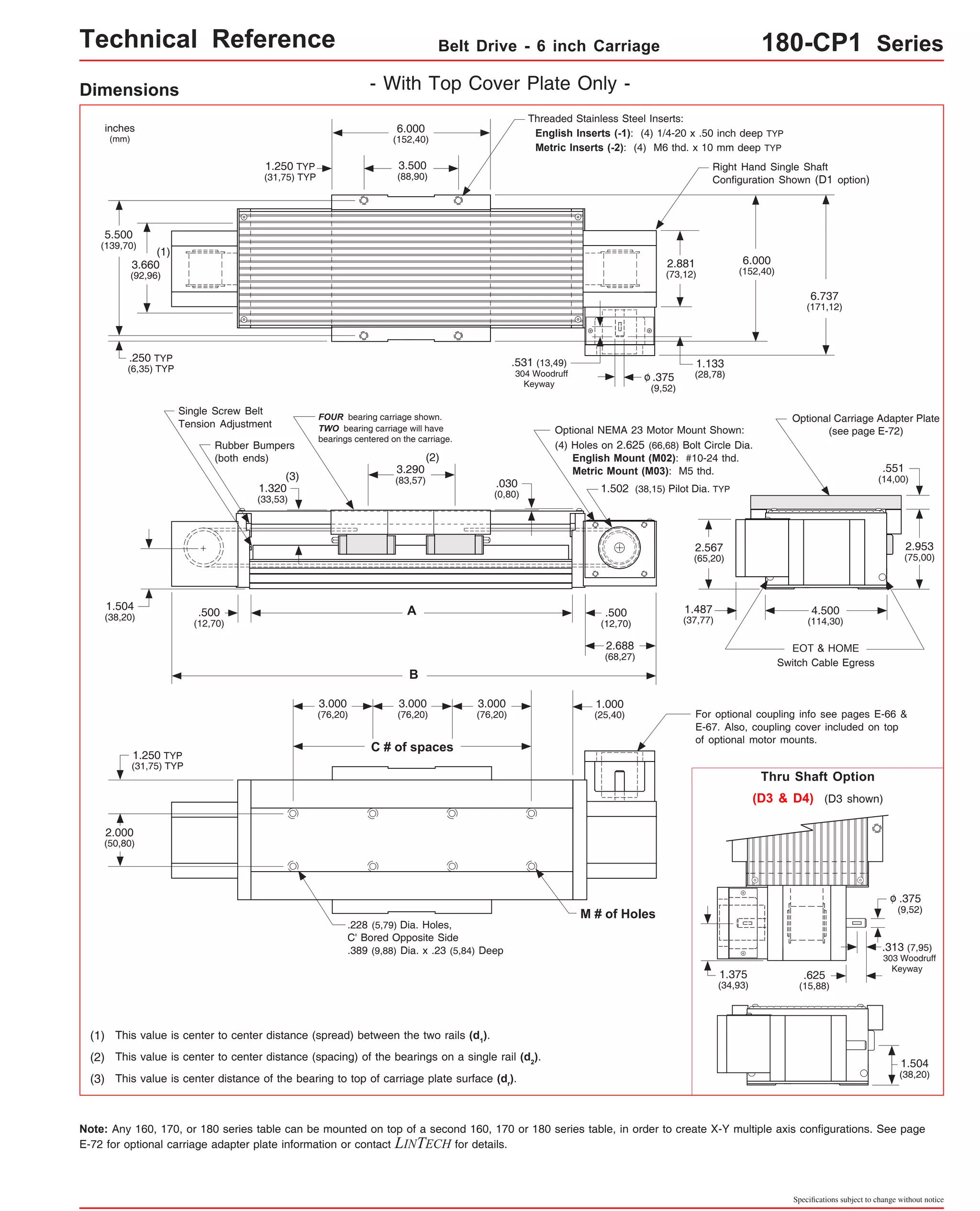
![Technical Reference Belt Drive - 6 inch Carriage 180-CP2 Series
Dimensions & Specifications
Travel
Length
Table Dimensions
Model
Number lbs
(1)
18x6072-CP2 72
(1825)
(1)
18x6084-CP2 84
(2130)
(1)
18x6096-CP2 96
(2435)
18x6108-CP2 108
(2740)
Sold & Serviced By:
Specifications subject to change without notice
(kg)
inches
(mm)
C
inches
(mm)
Mounting Dimensions
18x6006-CP2
inches
(mm)
A
B
18.250
(463,6)
Belt
Weight
ounces
(kg)
Table
Weight
3.8
(0,11)
(2)
18x6012-CP2
6
(150)
12
(300)
18x6018-CP2 18
(455)
18x6024-CP2 24
(605)
18x6030-CP2 30
(760)
18x6036-CP2 36
(910)
18x6042-CP2 42
(1060)
18x6048-CP2 48
(1215)
18x6060-CP2 60
(1520)
- With Top & Side Cover Plates -
M
3 8
24.250
(616,0)
5.3
5 12 (0,15)
30.250
(768,4)
6.8
7 16 (0,19)
36.250
(920,8)
8.3
9 20 (0,23)
42.250
(1073,2)
9.8
11 24 (0,28)
48.250
(1225,6)
11.3
13 28 (0,32)
54.250
(1378,0)
12.8
15 32 (0,36)
60.250
(1530,4)
14.3
17 36 (0,41)
72.250
(1835,2)
17.3
21 44 (0,49)
84.250
(2140,0)
12.125
(308,0)
18.125
(460,4)
24.125
(612,8)
30.125
(765,2)
36.125
(917,6)
42.125
(1070,0)
48.125
(1222,4)
54.125
(1374,8)
66.125
(1679,6)
x = 2; Carriage has 2 bearings; Carriage weight = 2.5 lbs. (1,13 kg)
x = 4; Carriage has 4 bearings; Carriage weight = 3.3 lbs. (1,50 kg)
20.3
25 52 (0,58)
96.250
(2444,8)
23.3
29 60 (0,66)
108.250
(2749,6)
26.3
33 68 (0,75)
120.250
(3054,4)
29.3
37 76 (0,83)
47.2
(21,4)
52.4
(23,8)
57.6
(26,1)
62.8
(28,5)
(1)
(1)
Footnotes:
(1) For travels greater than 60 inches (1520 mm) the top cover plate cannot be used due to the sag of the cover plate. Just the two side cover plates are
installed.
(2) Weight shown is with a 2 bearing carriage [2.5 lbs (1,13 kg)], a NEMA 23 motor mount [0.39 lbs (0,18 kg)], and a H100 style [0.08 lbs (0,04 kg)] coupling.
When using a 4 bearing carriage add 0.8 lbs (0,36 kg) to each value.
19.8
(9,0)
22.7
(10,3)
25.7
(11,7)
28.7
(13,0)
31.6
(14,3)
34.6
(15,7)
37.6
(17,1)
40.5
(18,4)
46.4
(21,0)
78.125
(1984,4)
90.125
(2289,2)
102.125
(2594,0)
114.125
(2898,8)
18x6054-CP2 54
(1370)
66.250
(1682,7)
15.8
19 40 (0,45) 43.5
(19,7)
60.125
(1527,1)
ELECTROMATE
Toll Free Phone (877) SERVO98
Toll Free Fax (877) SERV099
www.electromate.com
sales@electromate.com](https://image.slidesharecdn.com/lintechpositioningsystemscatalog-141018113223-conversion-gate01/75/Lintech-positioning-systems_catalog-227-2048.jpg)
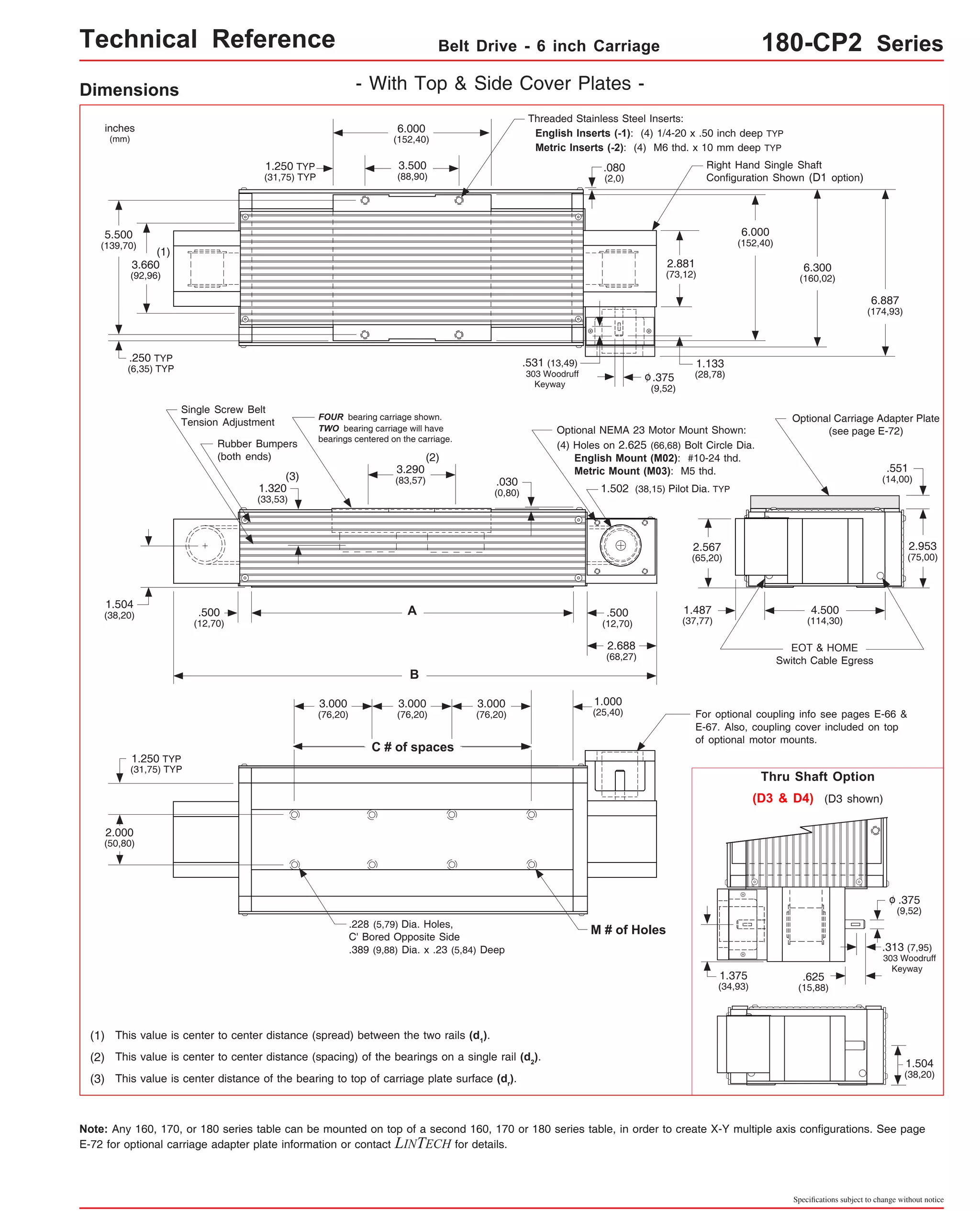
![Technical Reference Belt Drive - 6 inch Carriage 180-WC1 Series
Dimensions & Specifications
Travel
Length
Table Dimensions
Model
Number lbs
18x6041-WC1 41.5
(1050)
18x6056-WC1 56.7
(1440)
18x6065-WC1 65.5
(1660)
18x6074-WC1 74.5
(1890)
18x6084-WC1 84.0
(2130)
Sold & Serviced By:
Specifications subject to change without notice
(kg)
inches
(mm)
C
inches
(mm)
Mounting Dimensions
18x6003-WC1
inches
(mm)
A
B
Belt
Weight
ounces
(kg)
Table
Weight
3.8
(0,11)
(1)
18x6008-WC1
3.7
(94)
8.0
(203)
18x6012-WC1 12.8
(325)
18x6017-WC1 17.5
(444)
18x6022-WC1 22.0
(555)
18x6028-WC1 28.0
(710)
18x6032-WC1 32.5
(825)
18x6037-WC1 37.0
(935)
18x6047-WC1 47.5
(1205)
- With Waycovers -
M
3 8
5.3
5 12 (0,15)
6.8
7 16 (0,19)
8.3
9 20 (0,23)
9.8
11 24 (0,28)
11.3
13 28 (0,32)
12.8
15 32 (0,36)
14.3
17 36 (0,41)
17.3
21 44 (0,49)
18.0
(8,2)
20.4
(9,3)
22.8
(10,3)
25.3
(11,5)
27.5
(12,7)
29.9
(13,6)
32.3
(14,7)
34.7
(15,7)
39.8
(18,1)
12.125
(308,0)
18.125
(460,4)
24.125
(612,8)
30.125
(765,2)
36.125
(917,6)
42.125
(1070,0)
48.125
(1222,4)
54.125
(1374,8)
66.125
(1679,6)
78.125
(1984,4)
90.125
(2289,2)
102.125
(2594,0)
114.125
(2898,8)
18.250
(463,6)
24.250
(616,0)
30.250
(768,4)
36.250
(920,8)
42.250
(1073,2)
48.250
(1225,6)
54.250
(1378,0)
60.250
(1530,4)
66.250
(1682,7)
72.250
(1835,2)
84.250
(2140,0)
96.250
(2444,8)
108.250
(2749,6)
120.250
(3054,4)
x = 2; Carriage has 2 bearings; Carriage weight = 2.5 lbs. (1,13 kg)
x = 4; Carriage has 4 bearings; Carriage weight = 3.3 lbs. (1,50 kg)
20.3
25 52 (0,58)
23.3
29 60 (0,66)
26.3
33 68 (0,75)
29.3
37 76 (0,83)
45.0
(20,4)
50.2
(22,8)
55.4
(25,1)
60.6
(27,5)
Footnotes:
(1) Weight shown is with a 2 bearing carriage [2.5 lbs (1,13 kg)], a NEMA 23 motor mount [0.39 lbs (0,18 kg)], and a H100 style [0.08 lbs (0,04 kg)] coupling.
When using a 4 bearing carriage add 0.8 lbs (0,36 kg) to each value.
15.8
19 40 (0,45) 37.2
(16,9)
60.125
(1527,1)
ELECTROMATE
Toll Free Phone (877) SERVO98
Toll Free Fax (877) SERV099
www.electromate.com
sales@electromate.com](https://image.slidesharecdn.com/lintechpositioningsystemscatalog-141018113223-conversion-gate01/75/Lintech-positioning-systems_catalog-229-2048.jpg)
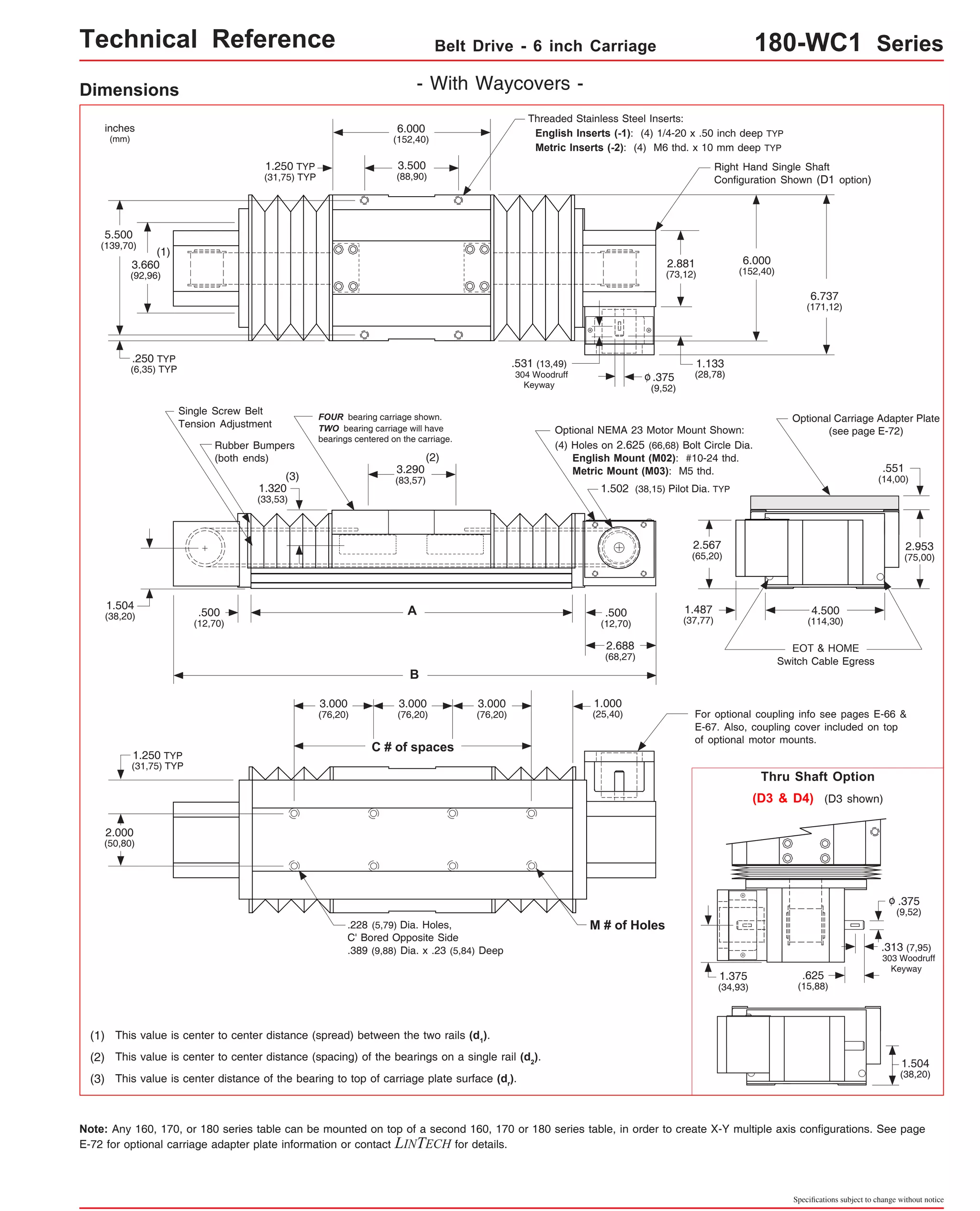

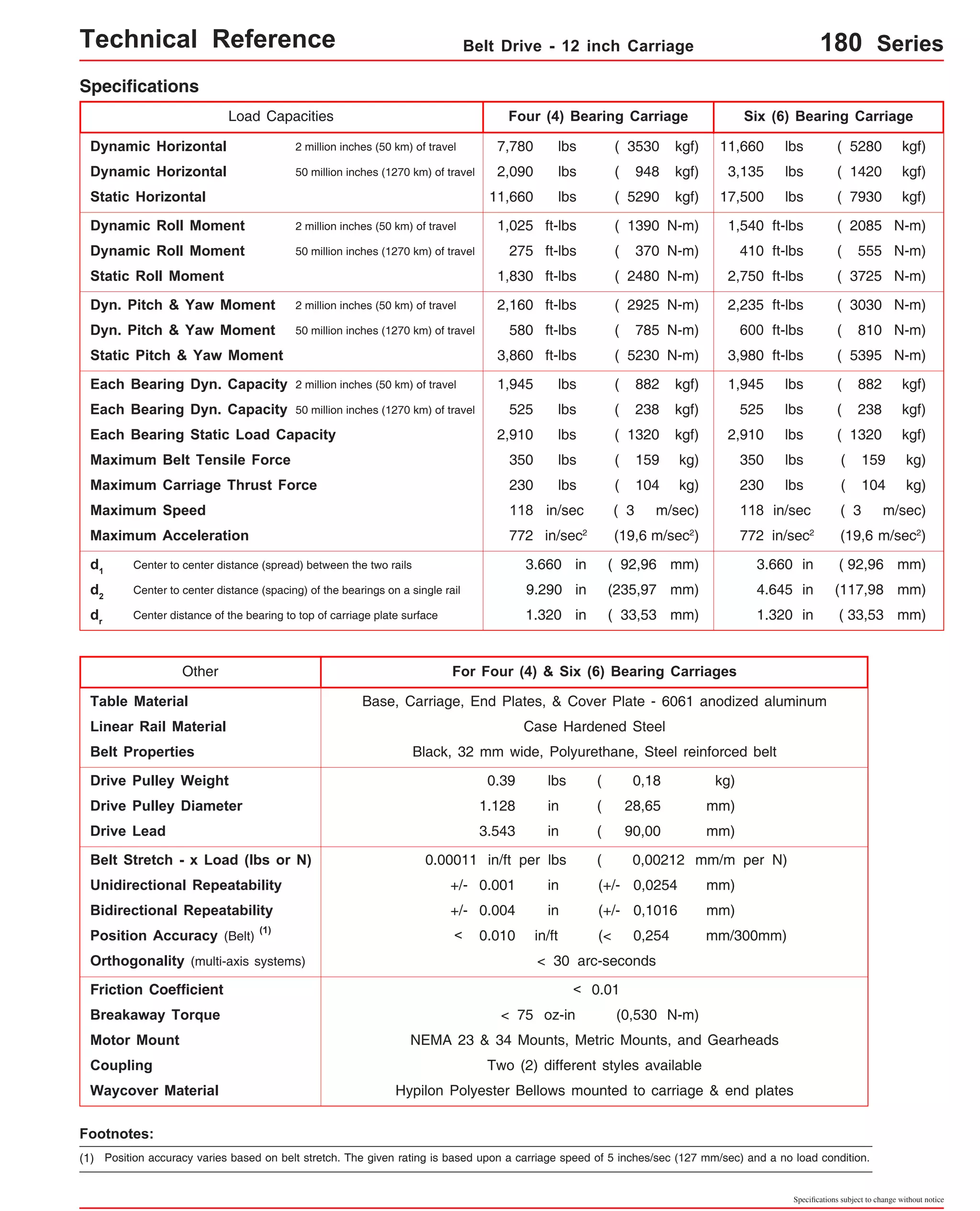
![Technical Reference Belt Drive - 12 inch Carriage 180-CP0 Series
Dimensions & Specifications
Travel
Length
Table Dimensions
Model
Number lbs
6
(150)
18x12012-CP0 12
(300)
18x12018-CP0 18
(455)
18x12024-CP0 24
(605)
18x12030-CP0 30
(760)
18x12036-CP0 36
(910)
18x12042-CP0 42
(1060)
Sold & Serviced By:
Specifications subject to change without notice
(kg)
inches
(mm)
C
inches
(mm)
Mounting Dimensions
18x12048-CP0
inches
(mm)
A
B
66.250
(463,6)
Belt
Weight
ounces
(kg)
Table
Weight
3.8
(0,11)
(1)
18x12006-CP0
48
(1215)
18x12054-CP0 54
(1370)
- Without Cover Plates -
M
19 40
24.250
(616,0)
5.3
5 12 (0,15)
30.250
(768,4)
6.8
7 16 (0,19)
36.250
(920,8)
8.3
9 20 (0,23)
42.250
(1073,2)
9.8
11 24 (0,28)
48.250
(1225,6)
11.3
13 28 (0,32)
54.250
(1378,0)
12.8
15 32 (0,36)
60.250
(1530,4)
14.3
17 36 (0,41)
72.250
(1835,2)
15.8
21 44 (0,45)
22.1
(10,0)
24.3
(11,0)
26.5
(12,0)
28.7
(13,0)
30.9
(14,0)
33.1
(15,0)
35.3
(16,0)
37.5
(17,0)
39.7
(18,0)
18x12066-CP0 66
(1675)
18x12078-CP0 78
(1980)
18x12090-CP0 90
(2285)
18x12102-CP0 102
(2590)
18.125
(460,4)
24.125
(612,8)
30.125
(765,2)
36.125
(917,6)
42.125
(1070,0)
48.125
(1222,4)
54.125
(1374,8)
78.125
(1984,4)
84.250
(2140,0)
20.3
25 52 (0,58)
90.125
(2289,2)
96.250
(2444,8)
23.3
29 60 (0,66)
102.125
(2594,0)
108.250
(2749,6)
26.3
33 68 (0,75)
114.125
(2898,8)
120.250
(3054,4)
29.3
37 76 (0,83)
44.1
(20,0)
48.5
(22,0)
52.9
(24,0)
57.3
(26,0)
Footnotes:
(1)
60.125
(308,0)
66.125
(1679,6)
x = 4; Carriage has 4 bearings; Carriage weight = 5.0 lbs. (2,27 kg)
x = 6; Carriage has 6 bearings; Carriage weight = 5.8 lbs. (2,63 kg)
Weight shown is with a 4 bearing carriage [5.0 lbs (2,26 kg)], a NEMA 23 motor mount [0.39 lbs (0,18 kg)], and a H100 style [0.08 lbs (0,04 kg)] coupling.
When using a 6 bearing carriage add 0.8 lbs (0,36 kg) to each value.
ELECTROMATE
Toll Free Phone (877) SERVO98
Toll Free Fax (877) SERV099
www.electromate.com
sales@electromate.com](https://image.slidesharecdn.com/lintechpositioningsystemscatalog-141018113223-conversion-gate01/75/Lintech-positioning-systems_catalog-233-2048.jpg)

![Technical Reference Belt Drive - 12 inch Carriage 180-CP1 Series
Dimensions & Specifications
Travel
Length
Table Dimensions
Model
Number lbs
3.8
19 40 (0,11) 41.5
(18,8)
17.3
(0,49)
44.1
(20,0)
x = 4; Carriage has 4 bearings; Carriage weight = 5.0 lbs. (2,27 kg)
x = 6; Carriage has 6 bearings; Carriage weight = 5.8 lbs. (2,63 kg)
Sold & Serviced By:
Specifications subject to change without notice
(kg)
inches
(mm)
C
inches
(mm)
Mounting Dimensions
18x12006-CP1
inches
(mm)
A
B
Belt
Weight
ounces
(kg)
(2)
Table
Weight
18x12012-CP1
6
(150)
12
(300)
18x12018-CP1 18
(455)
18x12024-CP1 24
(605)
18x12030-CP1 30
(760)
18x12036-CP1 36
(910)
18x12042-CP1 42
(1060)
18x12048-CP1 48
(1215)
18x12054-CP1 54
(1370)
- With Top Cover Plate Only -
M
24.250
(616,0)
5.3
5 12 (0,15)
30.250
(768,4)
6.8
7 16 (0,19)
36.250
(920,8)
8.3
9 20 (0,23)
42.250
(1073,2)
9.8
11 24 (0,28)
48.250
(1225,6)
11.3
13 28 (0,32)
54.250
(1378,0)
12.8
15 32 (0,36)
60.250
(1530,4)
14.3
17 36 (0,41)
66.250
(463,6)
72.250
(1835,2) 21 44
23.3
(10,6)
25.9
(11,7)
28.5
(12,9)
31.1
(14,1)
33.7
(15,3)
36.3
(16,5)
38.9
(17,6)
(1)
18.125
(460,4)
24.125
(612,8)
30.125
(765,2)
36.125
(917,6)
42.125
(1070,0)
48.125
(1222,4)
54.125
(1374,8)
60.125
(308,0)
66.125
(1679,6)
Footnotes:
(1) For travels greater than 54 inches (1520 mm) a top cover plate (-CP1) cannot be used due to the sag of the cover plate.
(2)
Weight shown is with a 4 bearing carriage [5.0 lbs (2,26 kg)], a NEMA 23 motor mount [0.39 lbs (0,18 kg)], and a H100 style [0.08 lbs (0,04 kg)] coupling.
When using a 6 bearing carriage add 0.8 lbs (0,36 kg) to each value.
ELECTROMATE
Toll Free Phone (877) SERVO98
Toll Free Fax (877) SERV099
www.electromate.com
sales@electromate.com](https://image.slidesharecdn.com/lintechpositioningsystemscatalog-141018113223-conversion-gate01/75/Lintech-positioning-systems_catalog-235-2048.jpg)
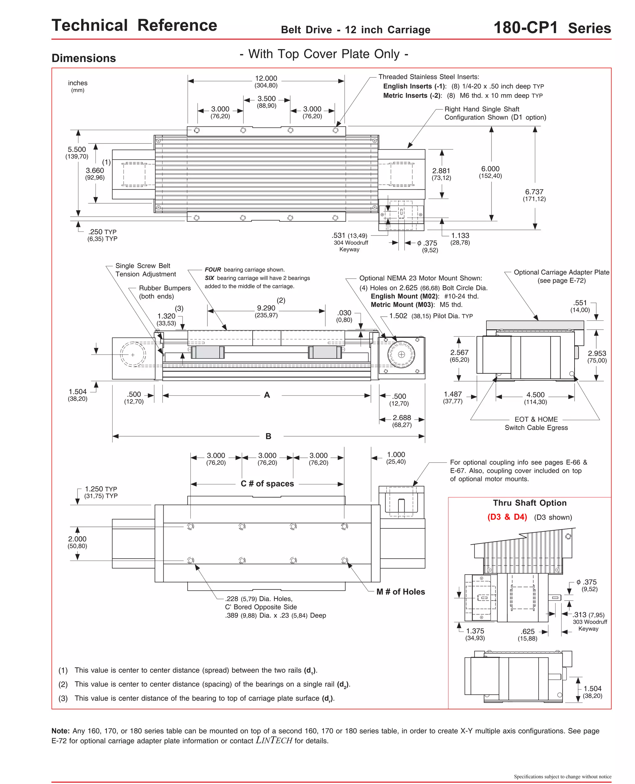
![Technical Reference Belt Drive - 12 inch Carriage 180-CP2 Series
Travel
Length
Table Dimensions
Model
Number lbs
18x12006-CP2
18x12012-CP2
18x12018-CP2
18x12024-CP2
18x12030-CP2
18x12036-CP2
18x12042-CP2
6
(150)
12
(300)
18
(455)
24
(605)
30
(760)
36
(910)
42
(1060)
(1) 66
18x12066-CP2
(1)
18x12078-CP2
(1)
(1675)
78
(1980)
18x12048-CP2
18x12054-CP2
18x12090-CP2
(1)
18x12102-CP2
48
(1215)
54
(1370)
90
(2285)
102
(2590)
Sold & Serviced By:
Specifications subject to change without notice
(kg)
inches
(mm)
C
inches
(mm)
Mounting Dimensions
inches
(mm)
A
B
18.250
(463,6)
Belt
Weight
ounces
(kg)
Table
Weight
3.8
(0,11)
(2)
Dimensions & Specifications - With Top & Side Cover Plates -
M
3 8
24.250
(616,0)
5.3
5 12 (0,15)
30.250
(768,4)
6.8
7 16 (0,19)
36.250
(920,8)
8.3
9 20 (0,23)
42.250
(1073,2)
9.8
11 24 (0,28)
48.250
(1225,6)
11.3
13 28 (0,32)
54.250
(1378,0)
12.8
15 32 (0,36)
60.250
(1530,4)
14.3
17 36 (0,41)
72.250
(1835,2)
17.3
21 44 (0,49)
84.250
(2140,0)
20.3
25 52 (0,58)
96.250
(2444,8)
23.3
29 60 (0,66)
108.250
(2749,6)
26.3
33 68 (0,75)
120.250
(3054,4)
29.3
37 76 (0,83)
25.2
(11,4)
28.2
(12,8)
31.2
(14,2)
34.1
(15,5)
37.1
(16,8)
40.1
(18,2)
43.0
(19,5)
46.0
(20,9)
49.7
(22,5)
54.9
(24,9)
60.1
(27,3)
65.3
(29,6)
(1)
12.125
(308,0)
18.125
(460,4)
24.125
(612,8)
30.125
(765,2)
36.125
(917,6)
42.125
(1070,0)
48.125
(1222,4)
54.125
(1374,8)
66.125
(1679,6)
Footnotes:
(1) For travels greater than 60 inches (1520 mm) the top cover plate cannot be used due to the sag of the cover plate. Just the two side cover plates are
installed.
(2)
78.125
(1984,4)
90.125
(2289,2)
102.125
(2594,0)
114.125
(2898,8)
x = 4; Carriage has 4 bearings; Carriage weight = 5.0 lbs. (2,27 kg)
x = 6; Carriage has 6 bearings; Carriage weight = 5.8 lbs. (2,63 kg)
48.9
(22,2)
Weight shown is with a 4 bearing carriage [5.0 lbs (2,26 kg)], a NEMA 23 motor mount [0.39 lbs (0,18 kg)], and a H100 style [0.08 lbs (0,04 kg)] coupling.
When using a 6 bearing carriage add 0.8 lbs (0,36 kg) to each value.
ELECTROMATE
Toll Free Phone (877) SERVO98
Toll Free Fax (877) SERV099
www.electromate.com
sales@electromate.com](https://image.slidesharecdn.com/lintechpositioningsystemscatalog-141018113223-conversion-gate01/75/Lintech-positioning-systems_catalog-237-2048.jpg)

![Technical Reference Belt Drive - 12 inch Carriage 180-WC1 Series
Travel
Length
Table Dimensions
Model
Number lbs
18x12003-WC1
18x12008-WC1
3.7
(90)
8.0
(203)
18x12012-WC1 12.8
(325)
18x12017-WC1 17.5
(444)
18x12022-WC1 22.0
(555)
18x12028-WC1 28.0
(710)
18x12032-WC1 32.5
(825)
18x12037-WC1 37.0
(935)
18x12041-WC1 41.5
(1050)
18x12053-WC1 53.5
(1355)
x = 4; Carriage has 4 bearings; Carriage weight = 5.0 lbs. (2,27 kg)
x = 6; Carriage has 6 bearings; Carriage weight = 5.8 lbs. (2,63 kg)
Footnotes:
(1)
Sold & Serviced By:
Specifications subject to change without notice
(kg)
inches
(mm)
C
inches
(mm)
Mounting Dimensions
inches
(mm)
A
B
Belt
Weight
ounces
(kg)
Table
Weight
3.8
(0,11)
(1)
Dimensions & Specifications - With Waycovers -
M
3 8
5.3
5 12 (0,15)
6.8
7 16 (0,19)
8.3
9 20 (0,23)
9.8
11 24 (0,28)
11.3
13 28 (0,32)
12.8
15 32 (0,36)
14.3
17 36 (0,41)
17.3
21 44 (0,49)
22.9
(10,4)
25.3
(11,5)
27.8
(12,6)
30.0
(13,6)
32.4
(14,7)
34.8
(15,8)
37.2
(16,9)
39.7
(18,0)
42.3
(19,2)
20.3
25 52 (0,58) 47.5
(21,5)
12.125
(308,0)
18.125
(460,4)
24.125
(612,8)
30.125
(765,2)
36.125
(917,6)
42.125
(1070,0)
48.125
(1222,4)
54.125
(1374,8)
66.125
(1679,6)
78.125
(1984,4)
18.250
(463,6)
24.250
(616,0)
30.250
(768,4)
36.250
(920,8)
42.250
(1073,2)
48.250
(1225,6)
54.250
(1378,0)
60.250
(1530,4)
72.250
(1835,2)
84.250
(2140,0)
Weight shown is with a 4 bearing carriage [5.0 lbs (2,26 kg)], a NEMA 23 motor mount [0.39 lbs (0,18 kg)], and a H100 style [0.08 lbs (0,04 kg)] coupling.
When using a 6 bearing carriage add 0.8 lbs (0,36 kg) to each value.
ELECTROMATE
Toll Free Phone (877) SERVO98
Toll Free Fax (877) SERV099
www.electromate.com
sales@electromate.com](https://image.slidesharecdn.com/lintechpositioningsystemscatalog-141018113223-conversion-gate01/75/Lintech-positioning-systems_catalog-239-2048.jpg)
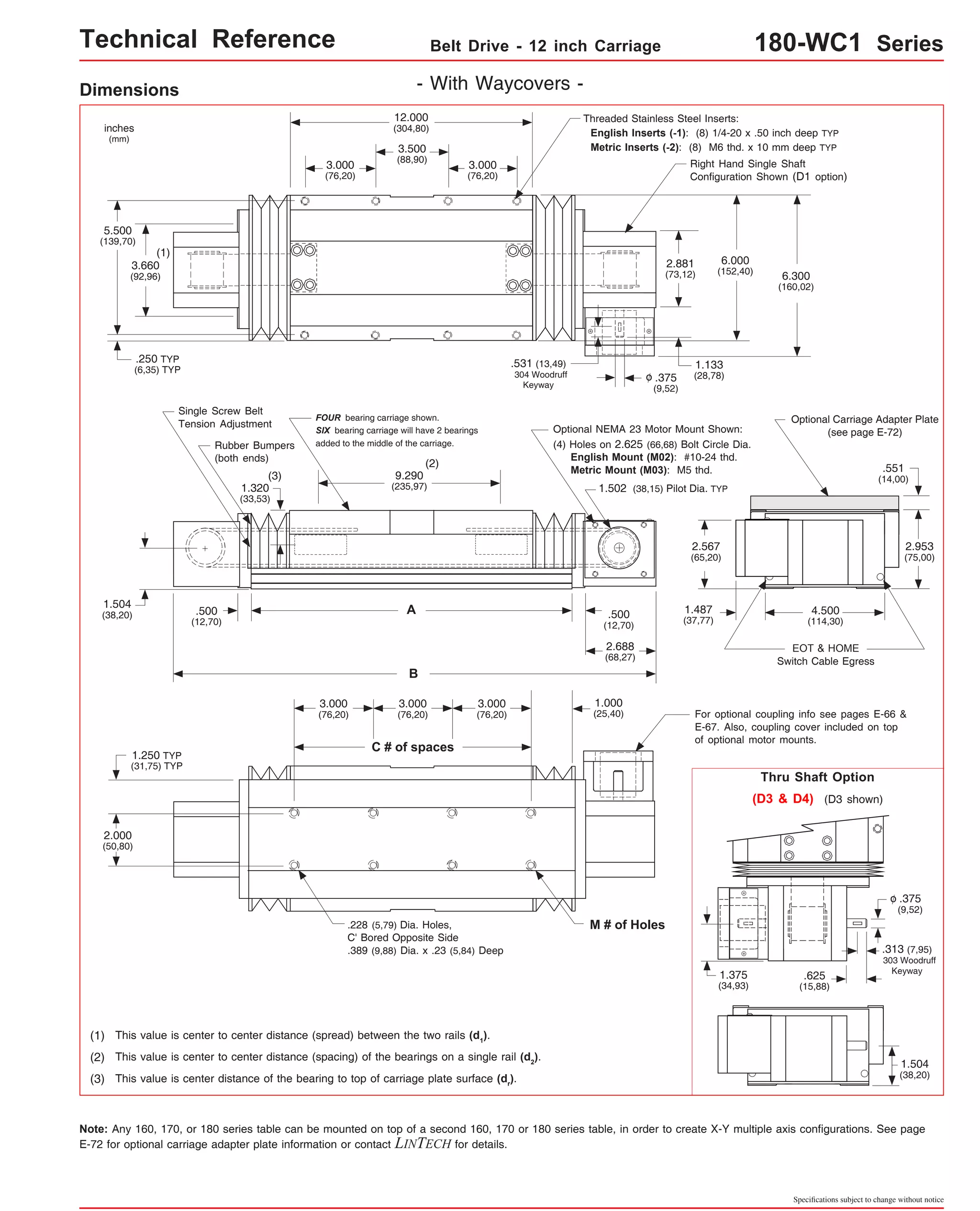

![Technical Reference - Belt Drive - 180 Series
Master/Slave 180 Series Configuration
For some X-Y belt drive applications, the
master/slave configuration shown to the right
may be required. This system provides two bot-tom
(X) axes spread apart a set distance, yet
driven by one motor. The spreading of the two
bottom axes minimizes the deflection on the Y
axis, reduces the moment loading on the X axes
carriages, increases the system rigidity, and
prevents twisting of the Y axis as it accelerates
to a set speed. LINTECH can provide the shaft
supports, the cross shaft, the couplings, and
the 180 series belt drive table without a motor
mount bracket. The shaft supports are required
as the couplings DO NOT provide adequate
support of the shaft by themselves. Also, the
shaft supports prevent the cross shaft from
"whipping" at long lengths and high speeds.
The chart below lists the maximum carriage
speed available with a given distance between
shaft supports. A minimum of two shaft supports
is always required. More than two can be used
to increase the speed of a longer spread sys-tem.
The equations below show the relationship
between the # of shaft supports, the spread be-tween
the two bottom axes (B), and the distance
between individual shaft supports (A).
inches
(mm) 1.000
Steel Cross Shaft: 0.500 inch (12,7 mm) diameter;
Example:
B = distance between 2 bottom axes
Maximum
Distance Between
Shaft Supports
(inches) (RPM)
30
36
48
<=
<=
<=
(in/sec)
54
60
66
<=
<=
<=
72
84
96
<=
<=
<=
108
<=
<= 120
118
89
50
39
32
26
22
16
12
10
8
2000
1500
840
660
535
440
370
270
208
164
133
A
Maximum
Shaft
Speed
Equivalent Car-riage
Speed
A = distance between shaft supports
2 Shaft Supports:
3 Shaft Supports:
4 Shaft Supports:
A = [B - 7.50 in (190,5 mm)]
A = [B - 8.53 in (216,7 mm)] / 2
A = [B - 9.56 in (242,8 mm)] / 3
Note: The user is required to supply the mounting surface
for the above configurations. LINTECH normally only sup-plies
all the positioning hardware. A common base plate can
be provided by LINTECH upon request.
Sold & Serviced By:
Specifications subject to change without notice
(mm)
762
914
1219
1372
1524
1676
1829
2134
2438
2743
3048
(mm/sec)
3000
2250
1260
990
802
660
555
405
312
246
200
A
(see chart)
Shaft Supports (203196)
B - 2.18
(B - 55,37)
(required shaft length)
Max. Ref.
C191 coupling C191 coupling
Shaft Supports (203196)
C' Bore for 1/4-20 (M6)
socket head cap screw
0.055 lbs/in (0,00098 kgf/mm);
Rockwell 60-65C
B
(25,4)
1.000 Max. Ref.
(25,4)
2.000
(50,8)
1.030
(26,16)
1.375
(34,93)
2.159
(54,84)
2.030
(51,56)
1.965
(49,91)
ELECTROMATE
Toll Free Phone (877) SERVO98
Toll Free Fax (877) SERV099
www.electromate.com
sales@electromate.com](https://image.slidesharecdn.com/lintechpositioningsystemscatalog-141018113223-conversion-gate01/75/Lintech-positioning-systems_catalog-242-2048.jpg)
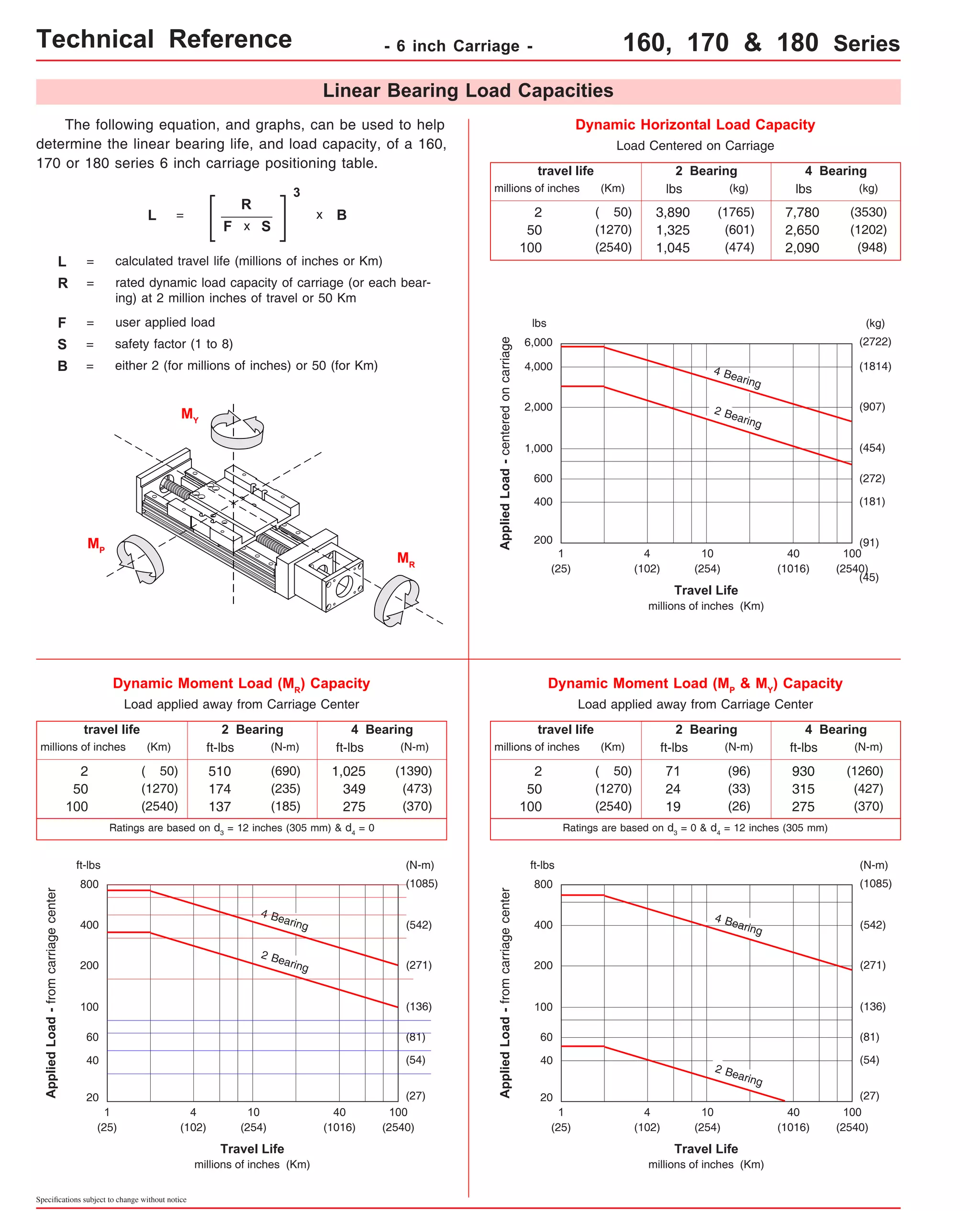
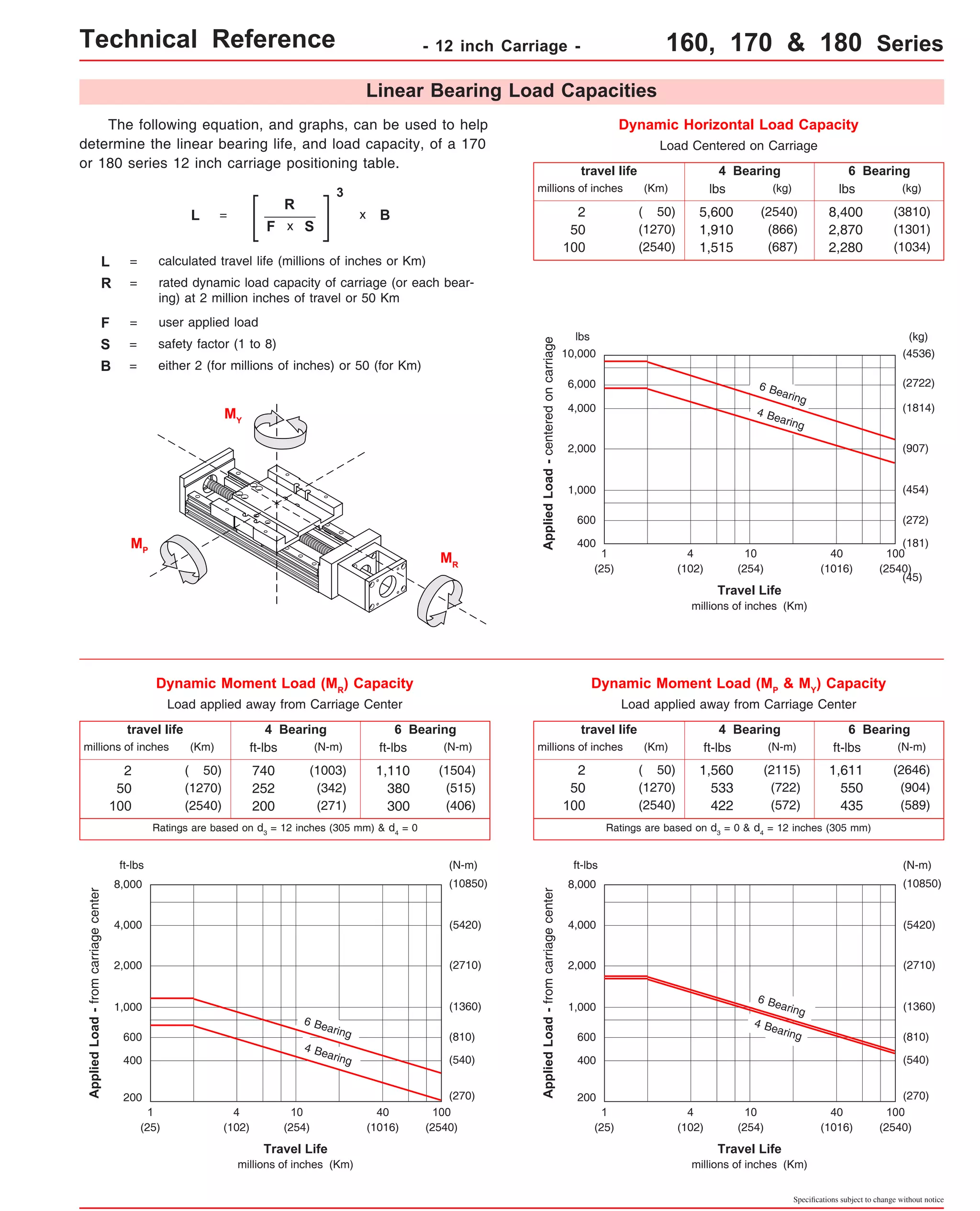
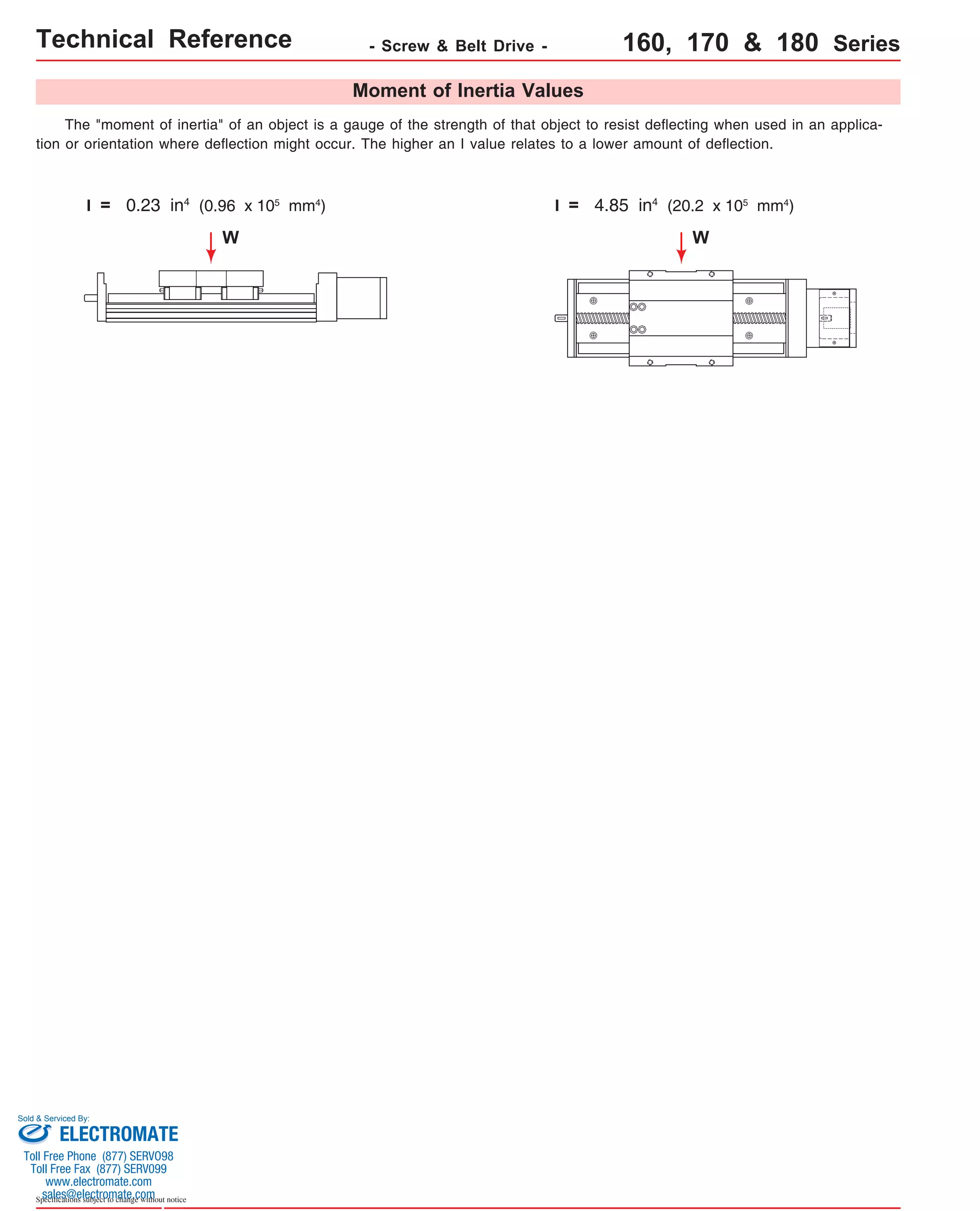
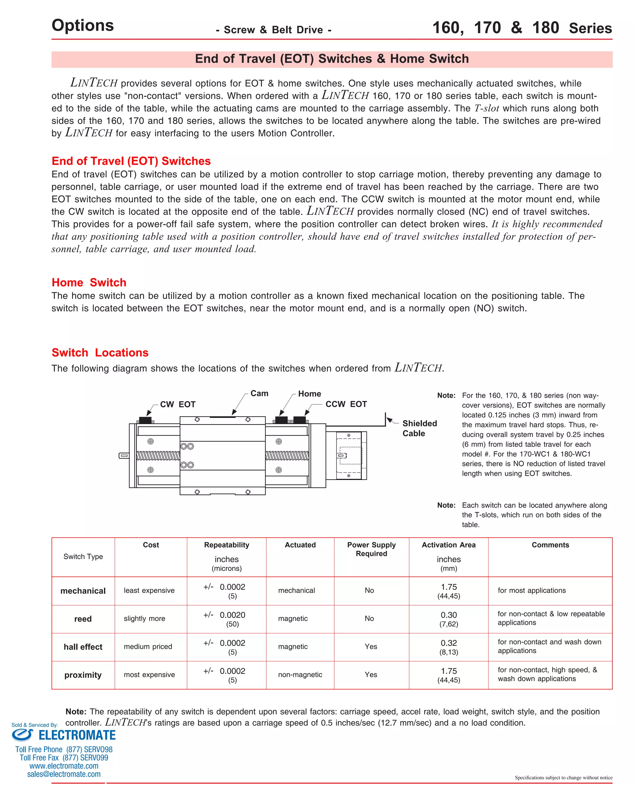

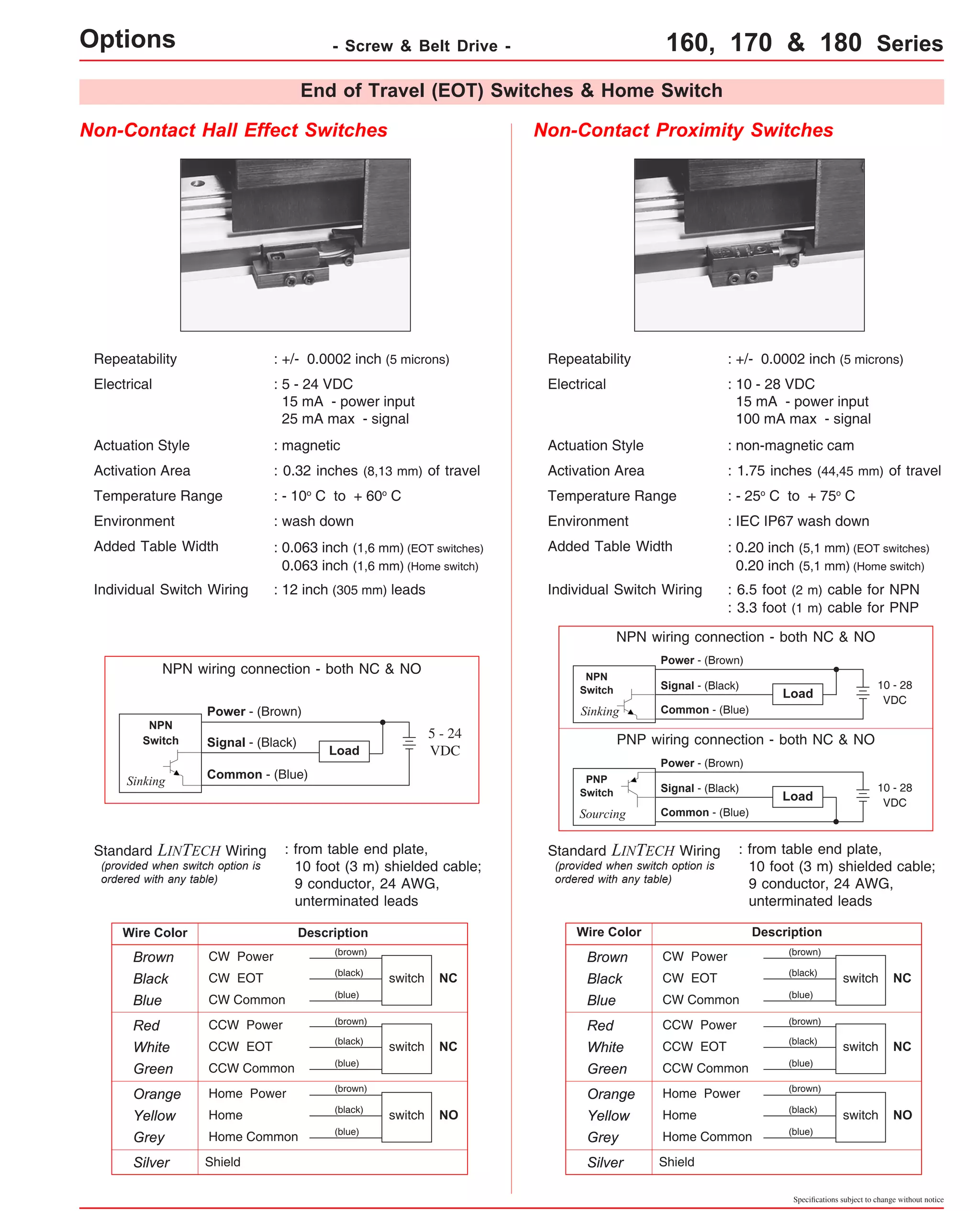
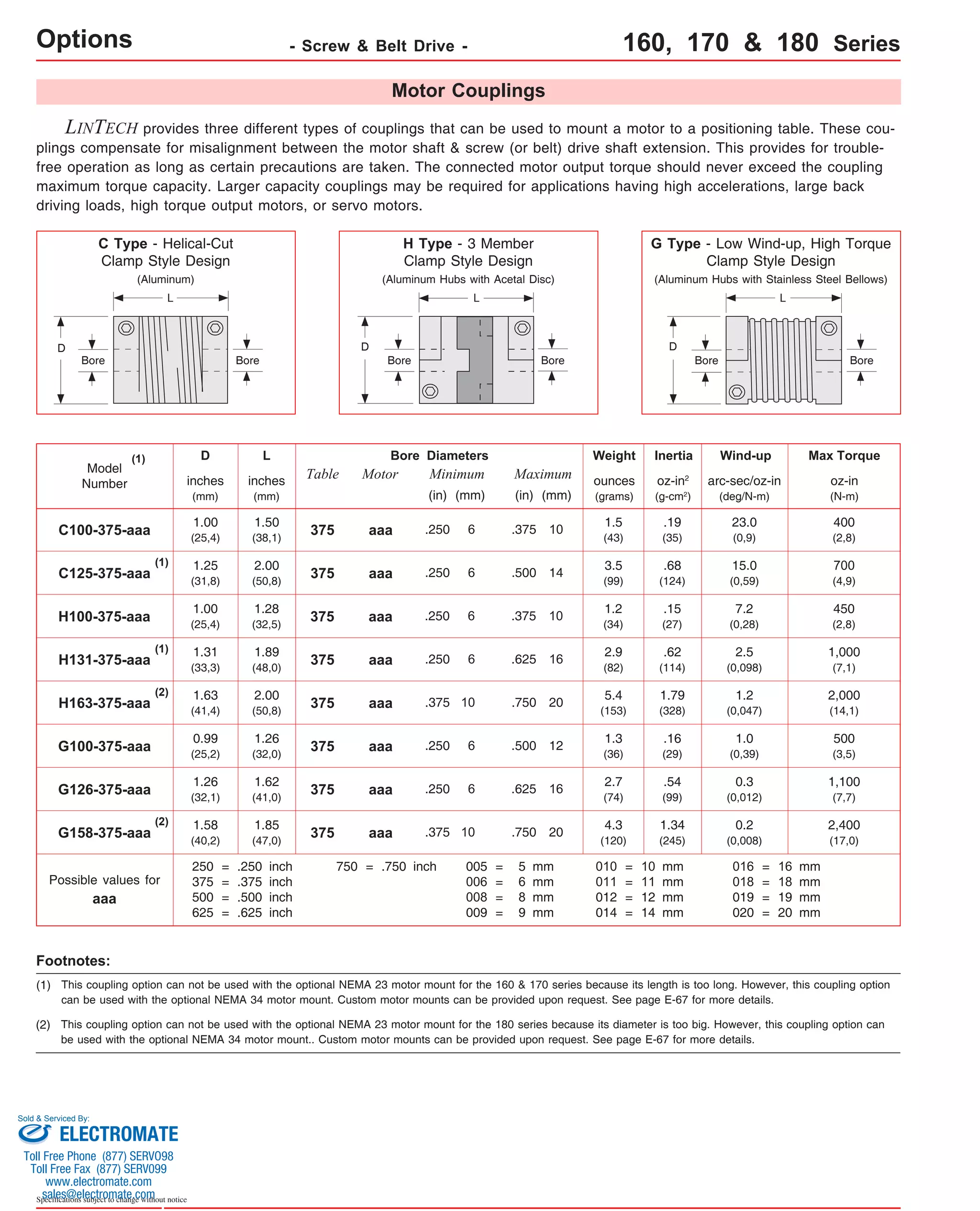

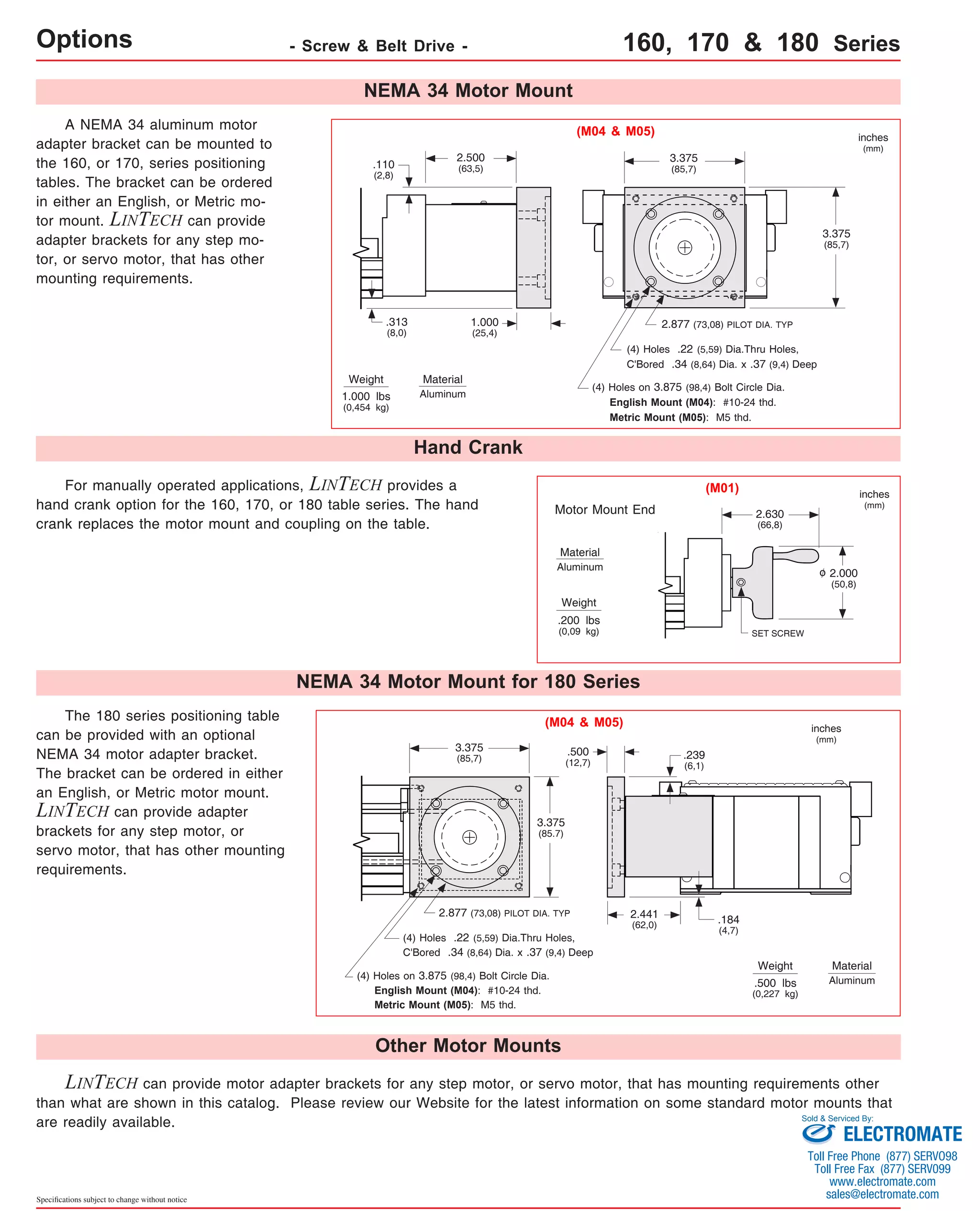
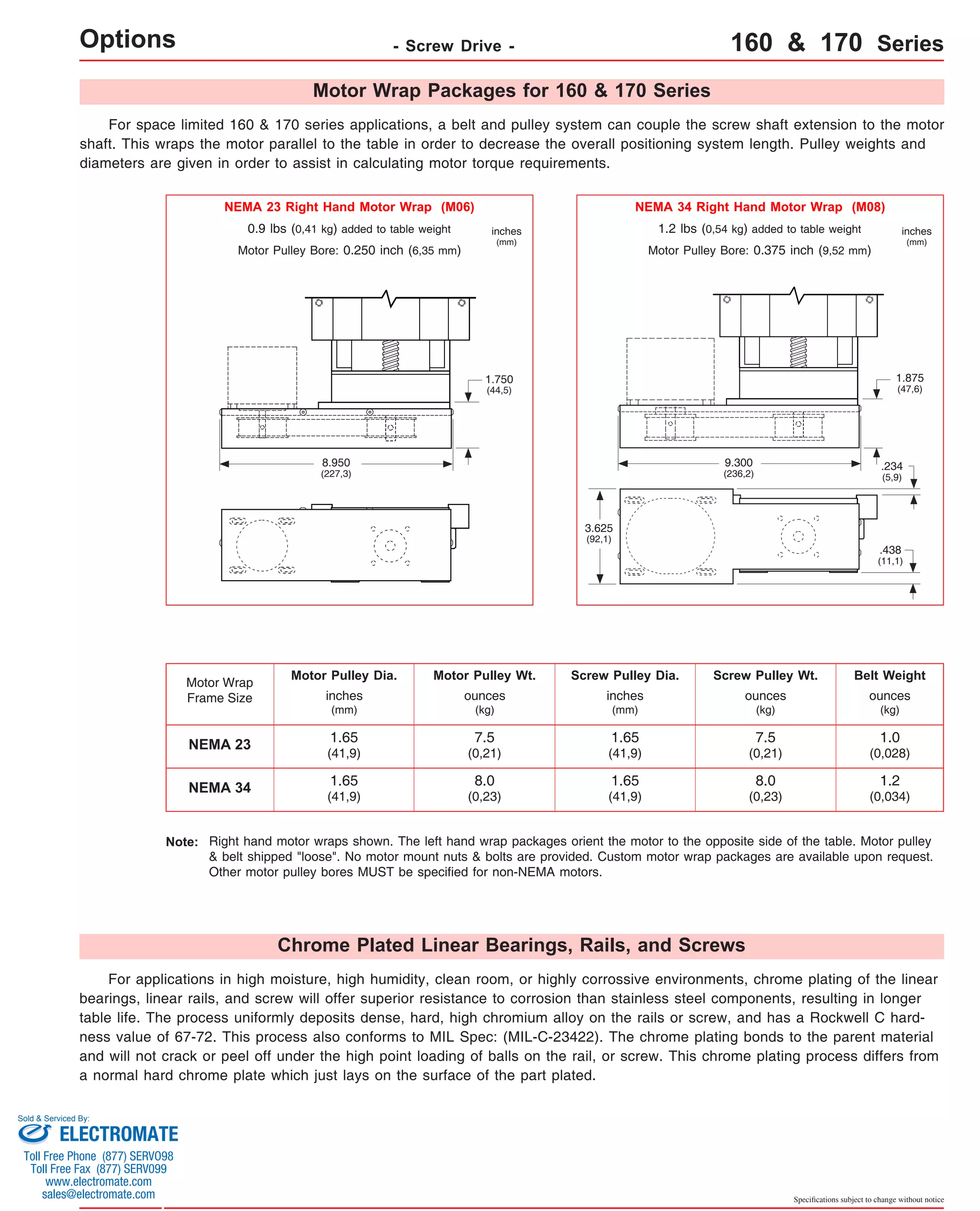
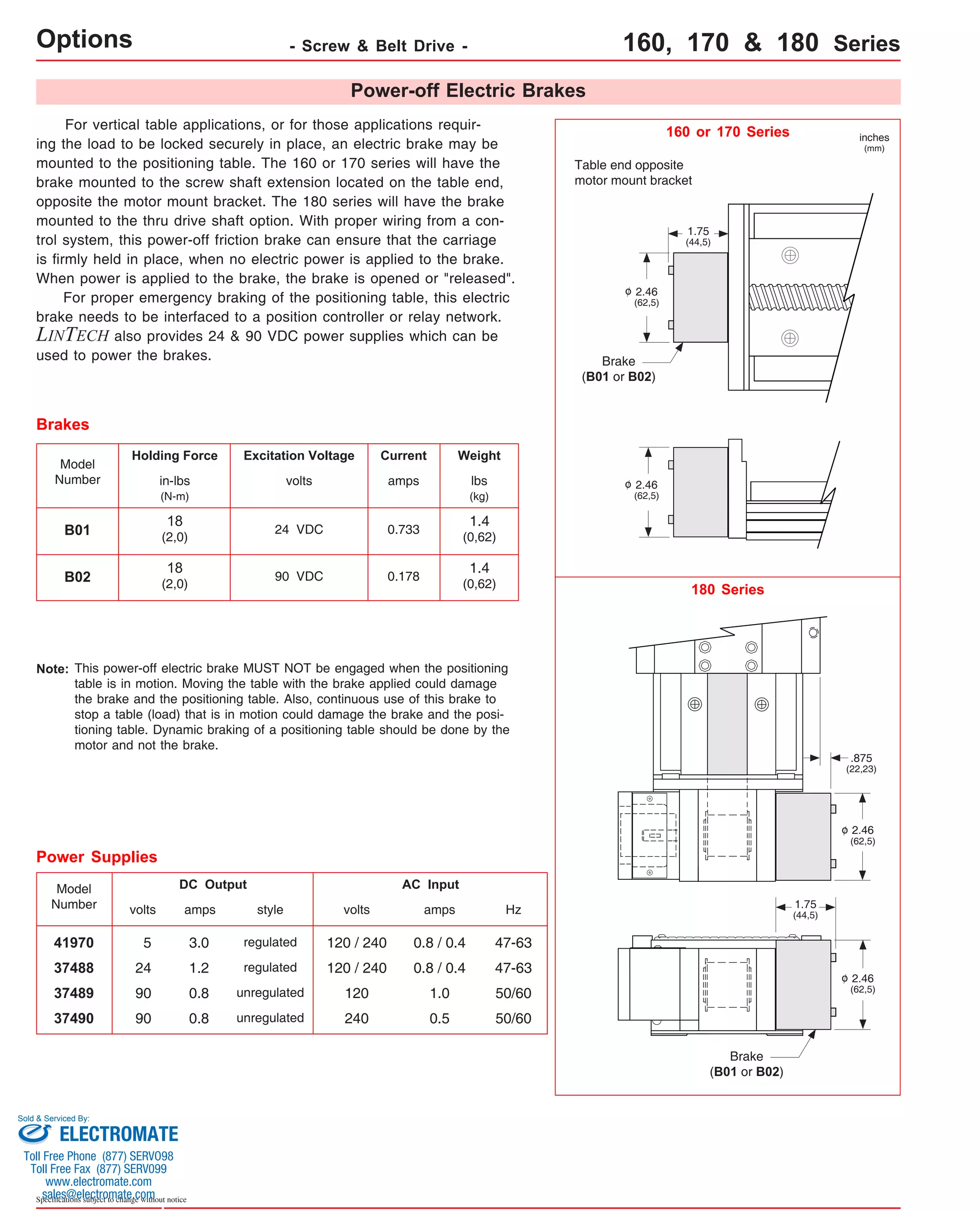
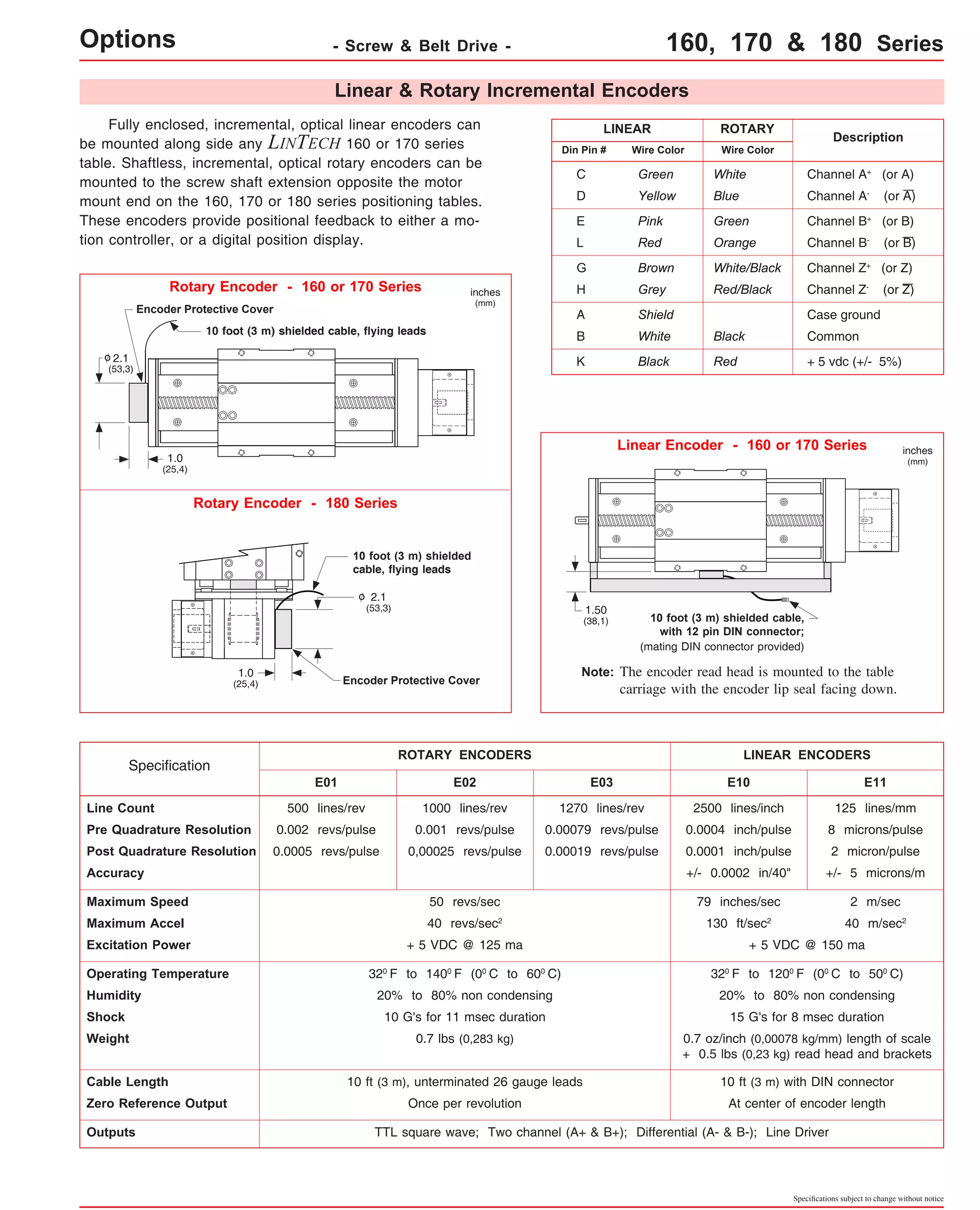
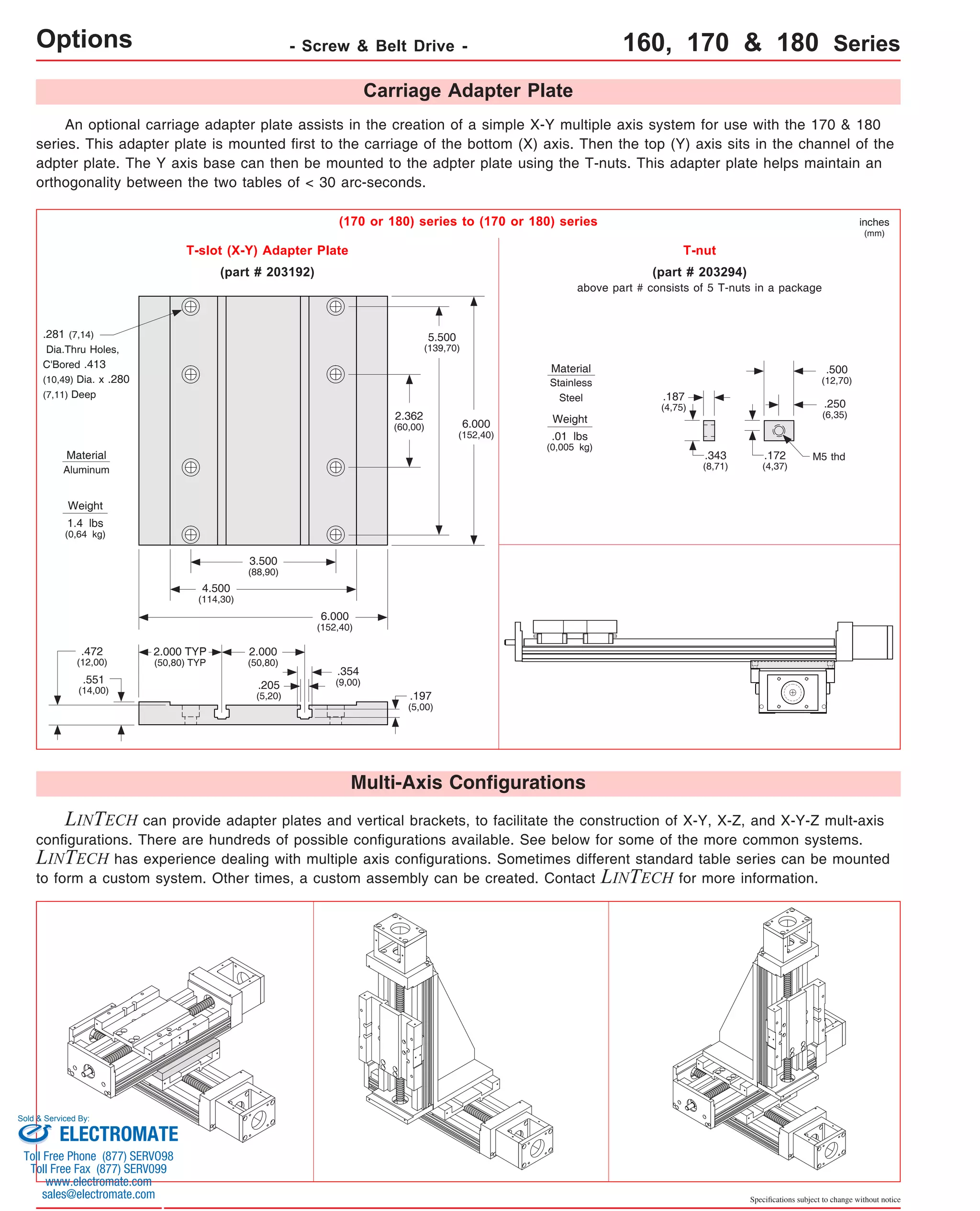
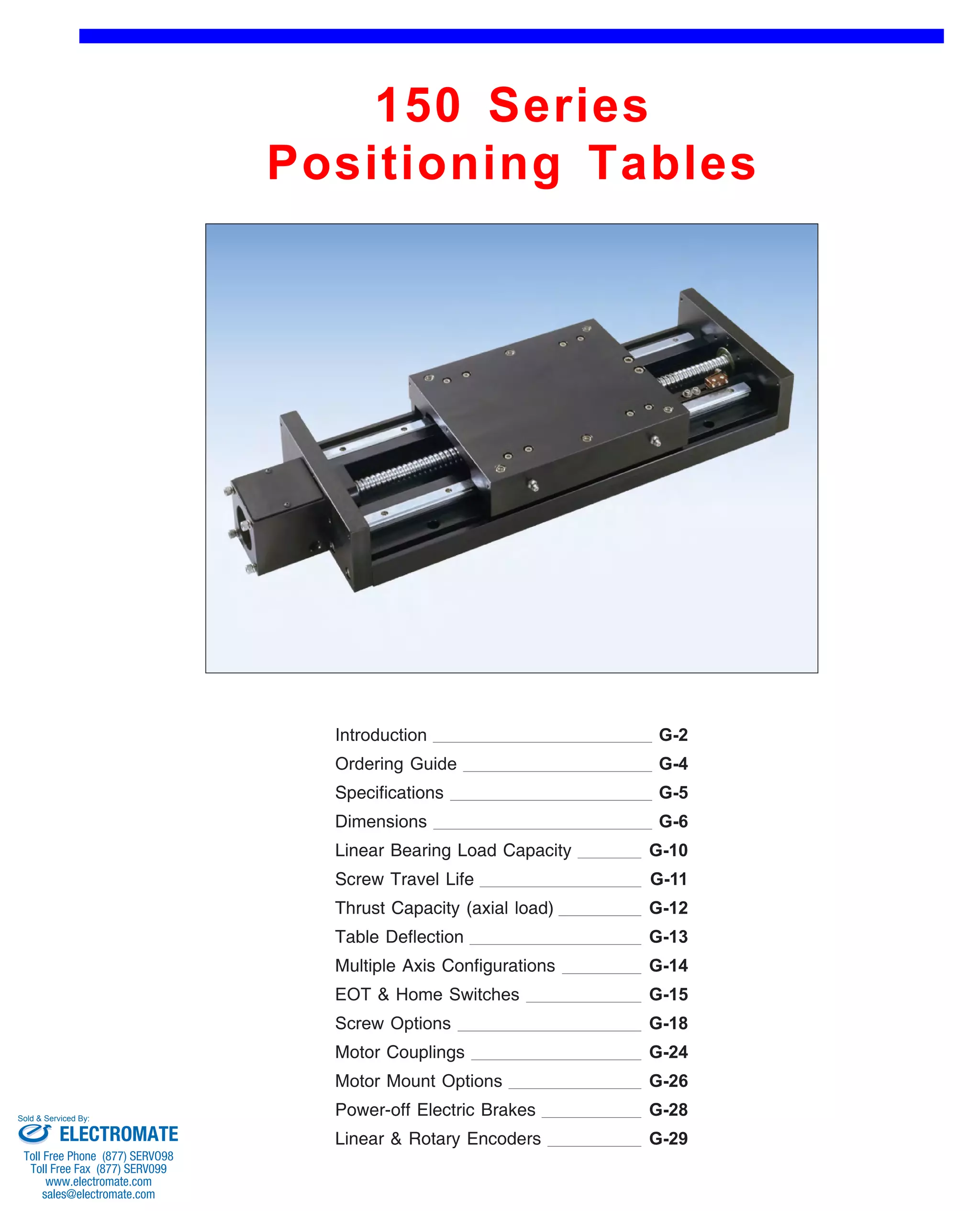
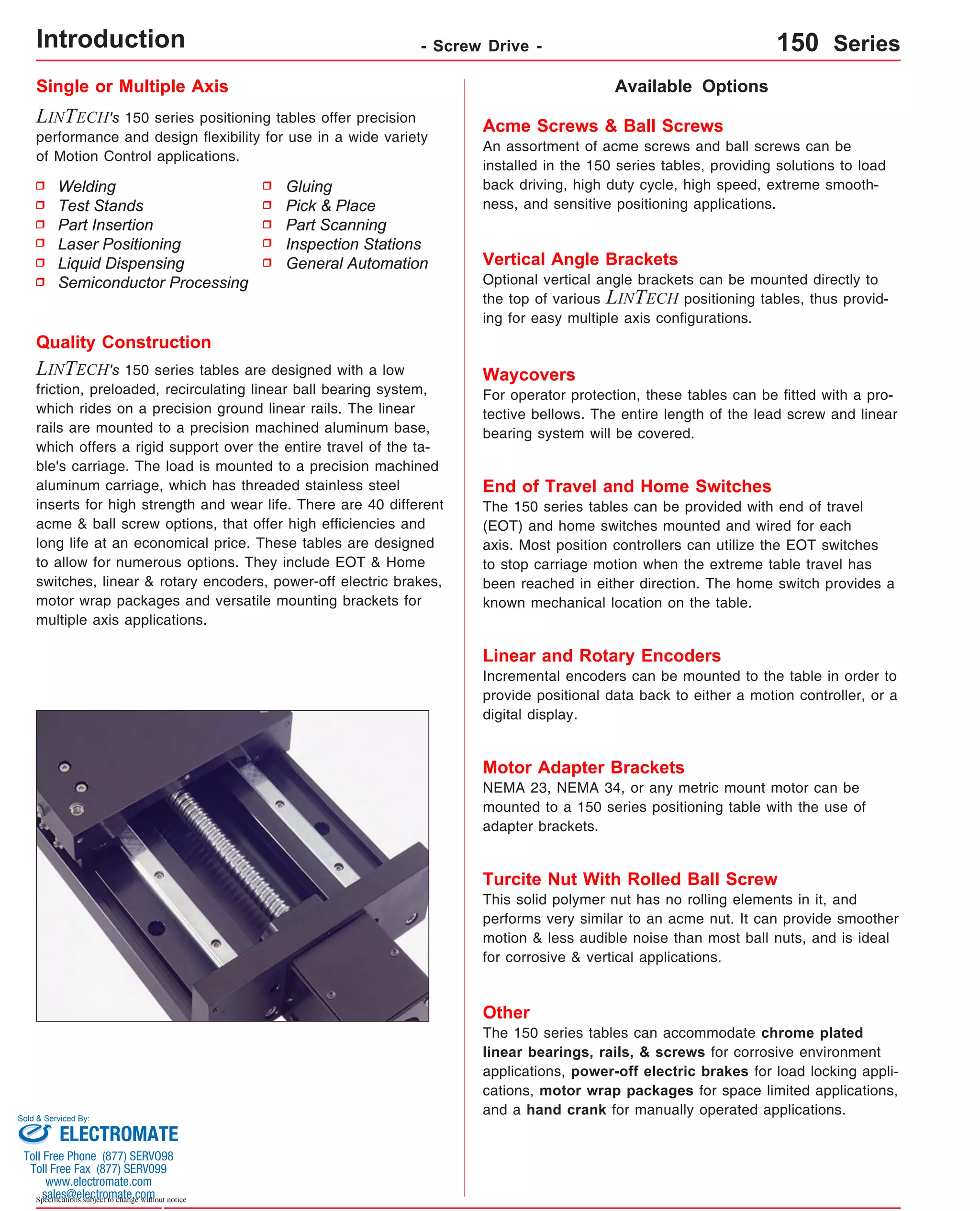
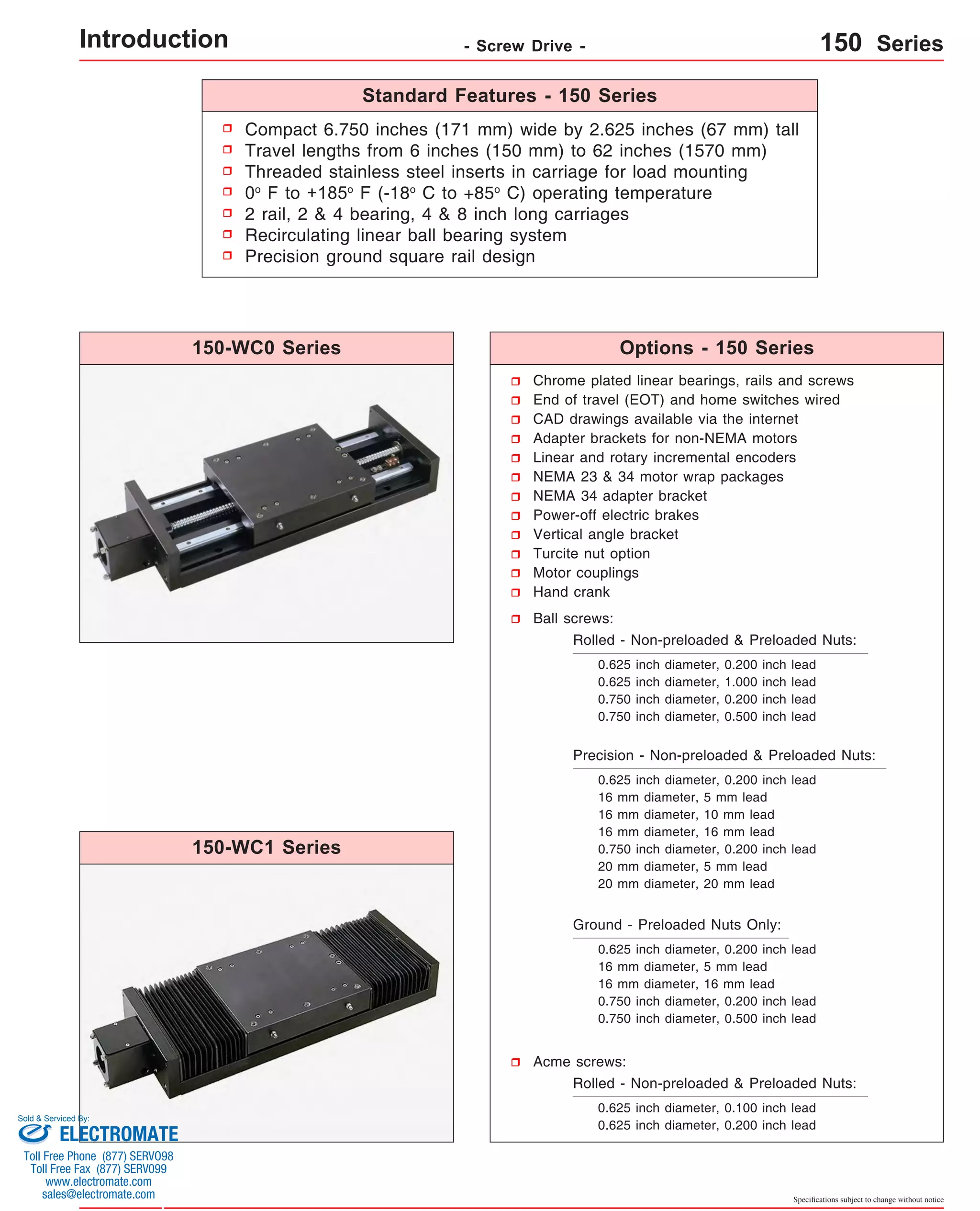
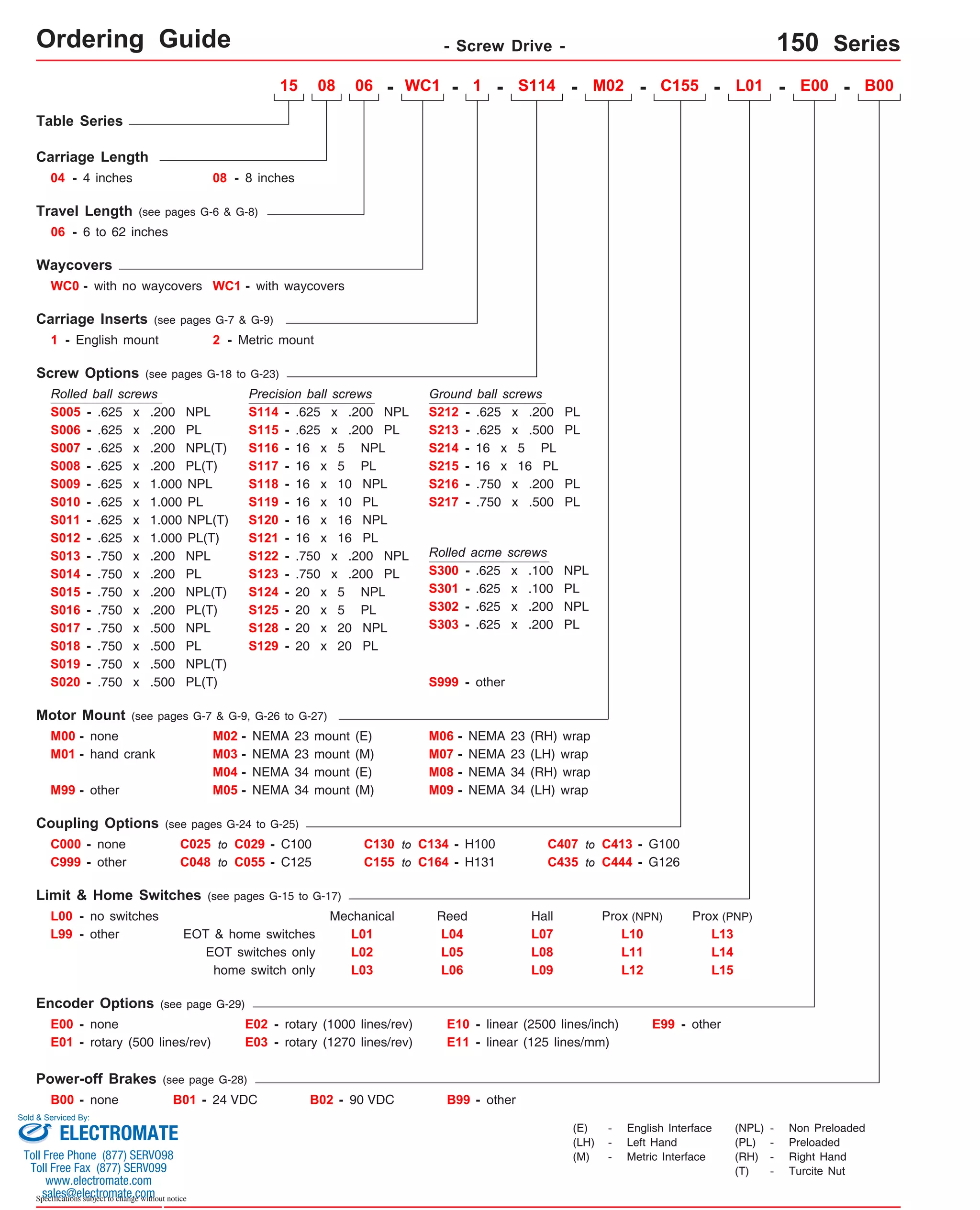
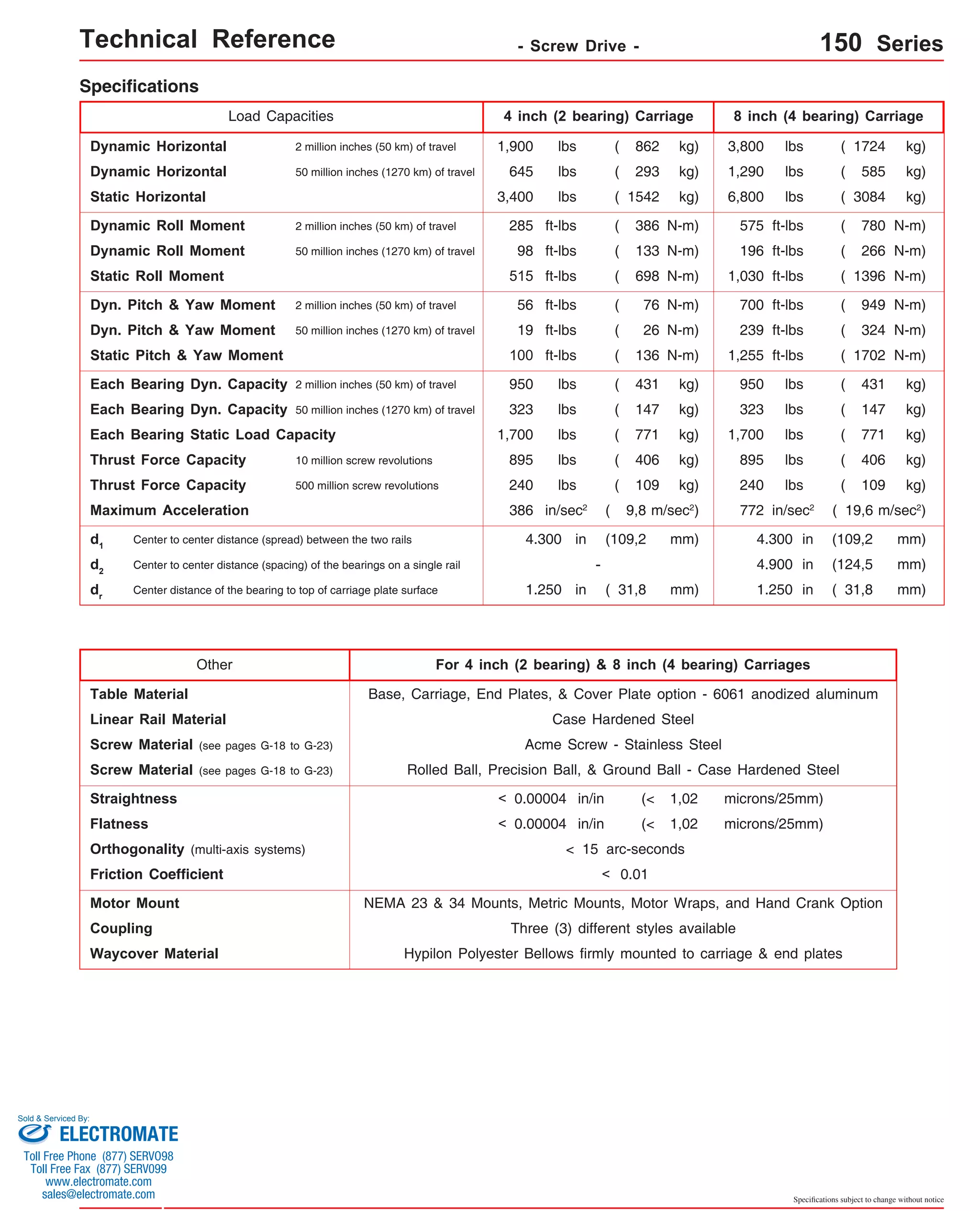
![Technical Reference - Screw Drive - 150-WC0 Series
Travel
Length
Table Dimensions
Model
Number lbs
inches
(mm)
1.250
(31,7) 16 30.41
(772) 23 7
(580)
1.380
(35,1) 20 38.16
(969) 31 9
(785)
1.500
(38,1) 24 45.91
(1166) 39 11
(990)
1.500
(38,1) 28 53.41
(1357) 46 13
(1165)
1.750
(44,4) 36 68.91
(1750) 62 17
(1570)
3.190
(81,0) 8 19.28
(490) 8 3
(200)
3.250
(82,5) 12 26.91
(684) 16 5
(400)
3.250
(82,5) 16 34.41
(874) 23 7
(580)
3.380
(85,8) 20 42.16
(1071) 31 9
(785)
1.875
(47,6) 38 72.91
(1852) 62 18
(1570)
Sold & Serviced By:
Specifications subject to change without notice
(kg)
inches
(mm)
C
inches
(mm)
Mounting Dimensions
A
150408-WC0
13.62
21.9
(345,9)
(9,9) B
16.12
(409,4)
1.190
(30,2)
D M
8
Screw
Length
inches
(mm)
15.28
(388)
Table
Weight
3
150416-WC0 21.25
23.75
1.250
5
12 22.91
28.4
(539,7)
(603,2)
(31,7) (582) (12,9) 8
(200)
16
(400)
150423-WC0 28.75
31.25
33.9
(730,2)
(793,7)
(15,4) Dimensions & Specifications
150431-WC0 36.50
39.00
40.3
(927,1)
(990,6)
(18,3) 150439-WC0 44.25
46.25
46.8
(1123,9)
(1174,7)
(21,2) 150446-WC0 51.75
54.25
53.3
(1314,4)
(1377,9)
(24,2) 150462-WC0 67.25
69.75
66.2
(1708,1)
(1771,6)
(30,0) 150808-WC0 17.62
20.12
24.9
(447,5)
(511,0)
(11,3) 150816-WC0 25.25
27.75
31.4
(641,3)
(704,8)
(15,0) 150823-WC0 32.75
35.25
37.9
(831,8)
(895,3)
(17,2) 150831-WC0 40.50
43.00
44.3
(1028,7)
(1092,2)
(20,1) 50.8
50.75
(1289,0)
3.500
(88,9) 24 49.91
150839-WC0 39
48.25
(990)
(1225,5)
11 (1268) (23,1) 150846-WC0 46 55.75
58.25
1.625
14
30 57.41
57.3
(1165)
(1416,0)
(1479,5)
(41,1)
(1458)
(26,0) 150862-WC0 71.25
73.75
70.2
(1809,7)
(1873,2)
(31,8) - Without Waycovers -
04 = 4 inch (101,6 mm) carriage length; 2 bearings; carriage weight = 4.0 lbs. (1,81 kg)
08 = 8 inch (203,2 mm) carriage length; 4 bearings; carriage weight = 7.0 lbs. (3,17 kg)
Footnotes:
(1)
(1)
Weight shown is with a 0.625 inch (16 mm) diameter screw, a NEMA 23 motor mount [0.34 lbs (0,16 kg)], and a C100 style [0.09 lbs (0,04 kg)] coupling.
When using a 0.750 inch (20 mm) diameter screw add 0.042 lbs per inch (0,00075 kg per mm) of screw length for a given model number.
version: 01/2014
ELECTROMATE
Toll Free Phone (877) SERVO98
Toll Free Fax (877) SERV099
www.electromate.com
sales@electromate.com](https://image.slidesharecdn.com/lintechpositioningsystemscatalog-141018113223-conversion-gate01/75/Lintech-positioning-systems_catalog-261-2048.jpg)
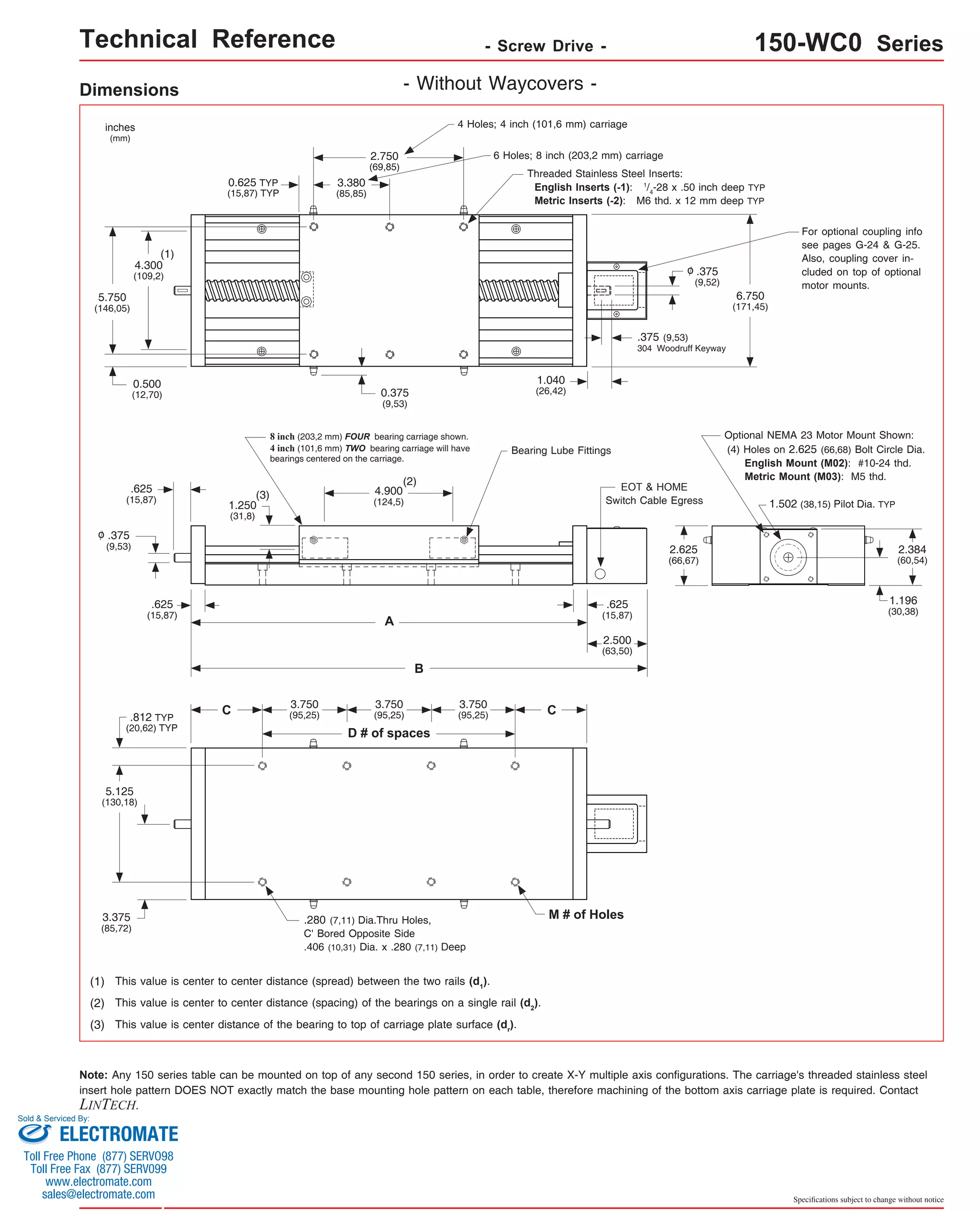
![Technical Reference - Screw Drive - 150-WC1 Series
Travel
Length
Table Dimensions
Model
Number lbs
inches
(mm)
1.250
(31,7) 18 7 16
(455)
1.380
(35,1) 24 9 20
(605)
1.500
(38,1) 30 11 24
(760)
1.500
(38,1) 36 13 28
(910)
1.750
(44,4) 48 17 36
(1215)
3.190
(81,0) 6 3 8
(150)
3.250
(82,5) 12 5 12
(300)
3.250
(82,5) 18 7 16
(455)
3.380
(85,8) 24 9 20
(605)
3.500
(88,9) 11 24 30
(760)
36 14 30
(910)
1.875
(47,6) 48 18 38
(1215)
Sold & Serviced By:
Specifications subject to change without notice
(kg)
inches
(mm)
C
inches
(mm)
Mounting Dimensions
A
150406-WC1
13.62
23.0
(345,9)
(10,4) B
16.12
(409,4)
1.190
(30,2)
D M
8
Screw
Length
inches
(mm)
Table
Weight
3
15.28
(388)
22.91
(582)
30.41
(772)
38.16
(969)
45.91
(1166)
53.41
(1357)
68.91
(1750)
19.28
(490)
26.91
(684)
34.41
(874)
42.16
(1071)
49.91
(1268)
57.41
(1458)
72.91
(1852)
150412-WC1 21.25
23.75
1.250
5 12
30.0
(539,7)
(603,2)
(31,7) (13,6) 6
(150)
12
(300)
150418-WC1 28.75
31.25
36.0
(730,2)
(793,7)
(16,3) Dimensions & Specifications
150424-WC1 36.50
39.00
43.0
(927,1)
(990,6)
(19,5) 150430-WC1 44.25
46.25
50.0
(1123,9)
(1174,7)
(22,7) 150436-WC1 51.75
54.25
57.0
(1314,4)
(1377,9)
(25,8) 150448-WC1 67.25
69.75
71.0
(1708,1)
(1771,6)
(32,2) 150806-WC1 17.62
20.12
26.0
(447,5)
(511,0)
(11,8) 150812-WC1 25.25
27.75
33.0
(641,3)
(704,8)
(15,0) 150818-WC1 32.75
35.25
40.0
(831,8)
(895,3)
(18,1) 150824-WC1 40.50
43.00
47.0
(1028,7)
(1092,2)
(21,3) 54.0
50.75
(1289,0)
150830-WC1 (24,5) 48.25
(1225,5)
150836-WC1 55.75
58.25
1.625
61.0
(1416,0)
(1479,5)
(41,1)
(27,7) 150848-WC1 71.25
73.75
75.0
(1809,7)
(1873,2)
(34,0) - With Waycovers -
04 = 4 inch (101,6 mm) carriage length; 2 bearings; carriage weight = 4.0 lbs. (1,81 kg)
08 = 8 inch (203,2 mm) carriage length; 4 bearings; carriage weight = 7.0 lbs. (3,17 kg)
(1)
Footnotes:
(1) Weight shown is with a 0.625 inch (16 mm) diameter screw, a NEMA 23 motor mount [0.34 lbs (0,16 kg)], and a C100 style [0.09 lbs (0,04 kg)] coupling.
When using a 0.750 inch (20 mm) diameter screw add 0.042 lbs per inch (0,00075 kg per mm) of screw length for a given model number.
ELECTROMATE
Toll Free Phone (877) SERVO98
Toll Free Fax (877) SERV099
www.electromate.com
sales@electromate.com](https://image.slidesharecdn.com/lintechpositioningsystemscatalog-141018113223-conversion-gate01/75/Lintech-positioning-systems_catalog-263-2048.jpg)

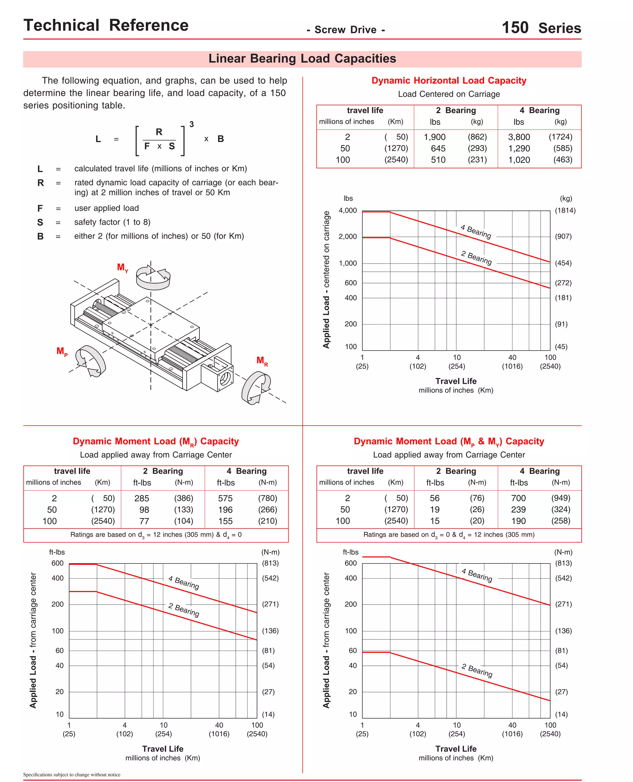
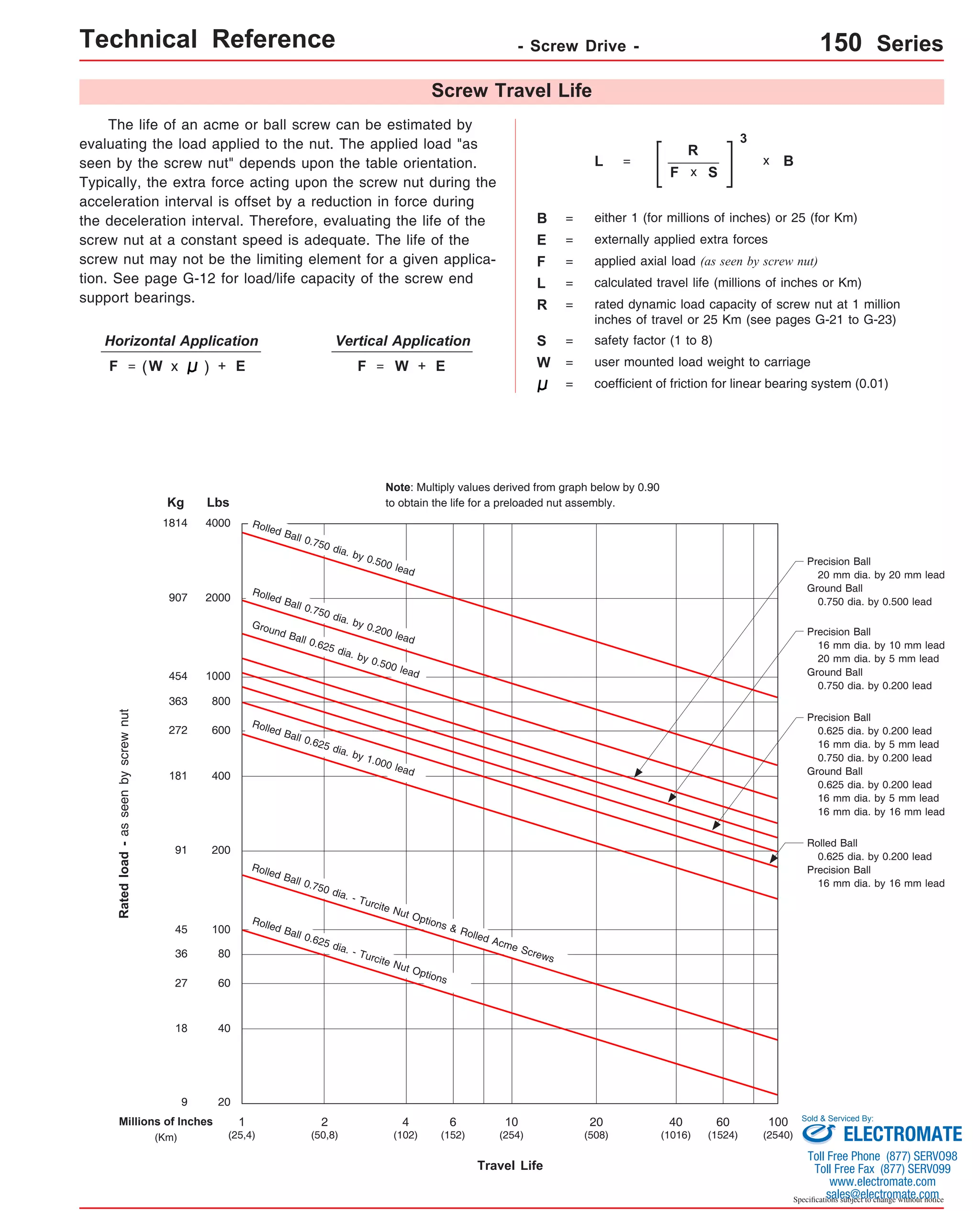

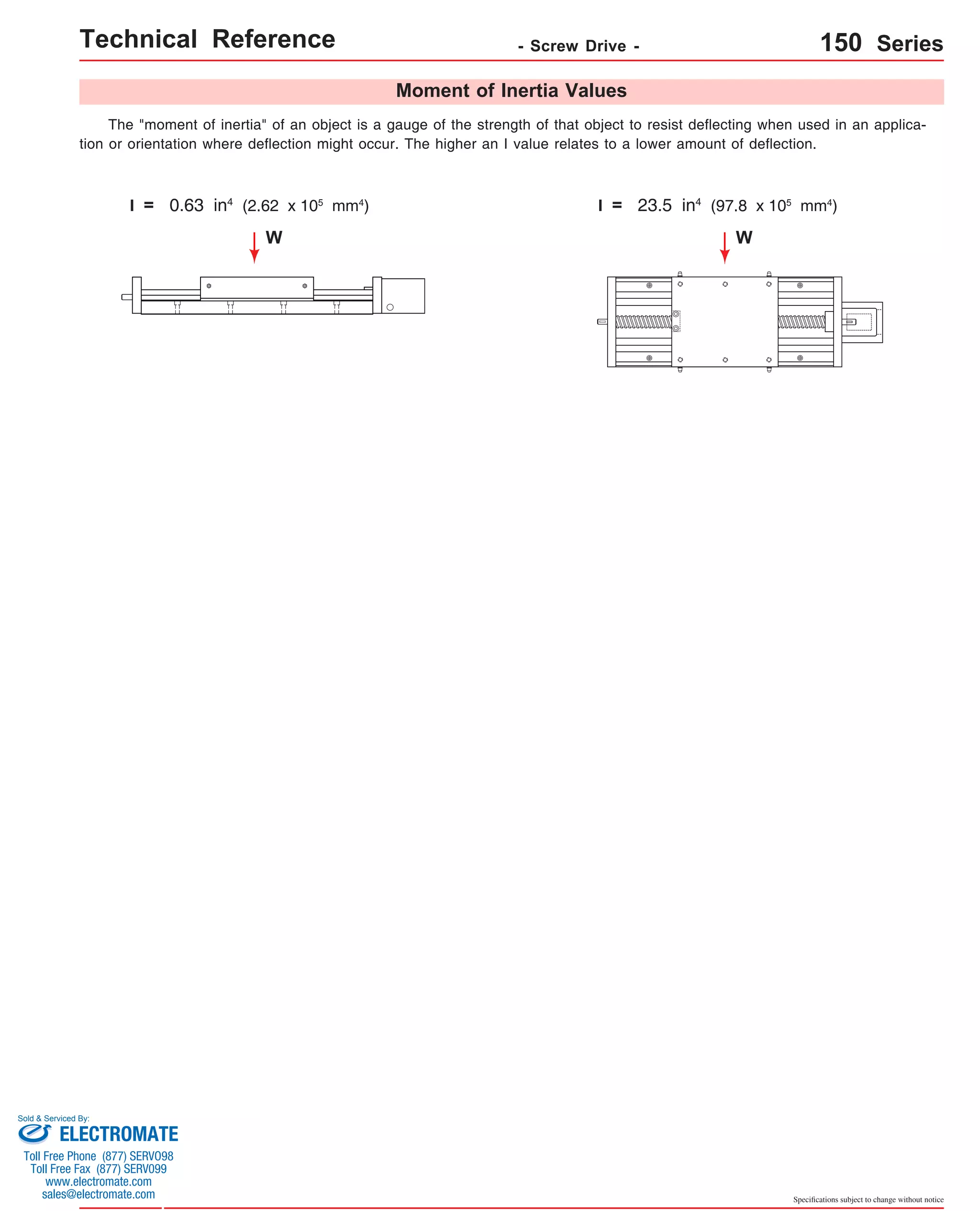
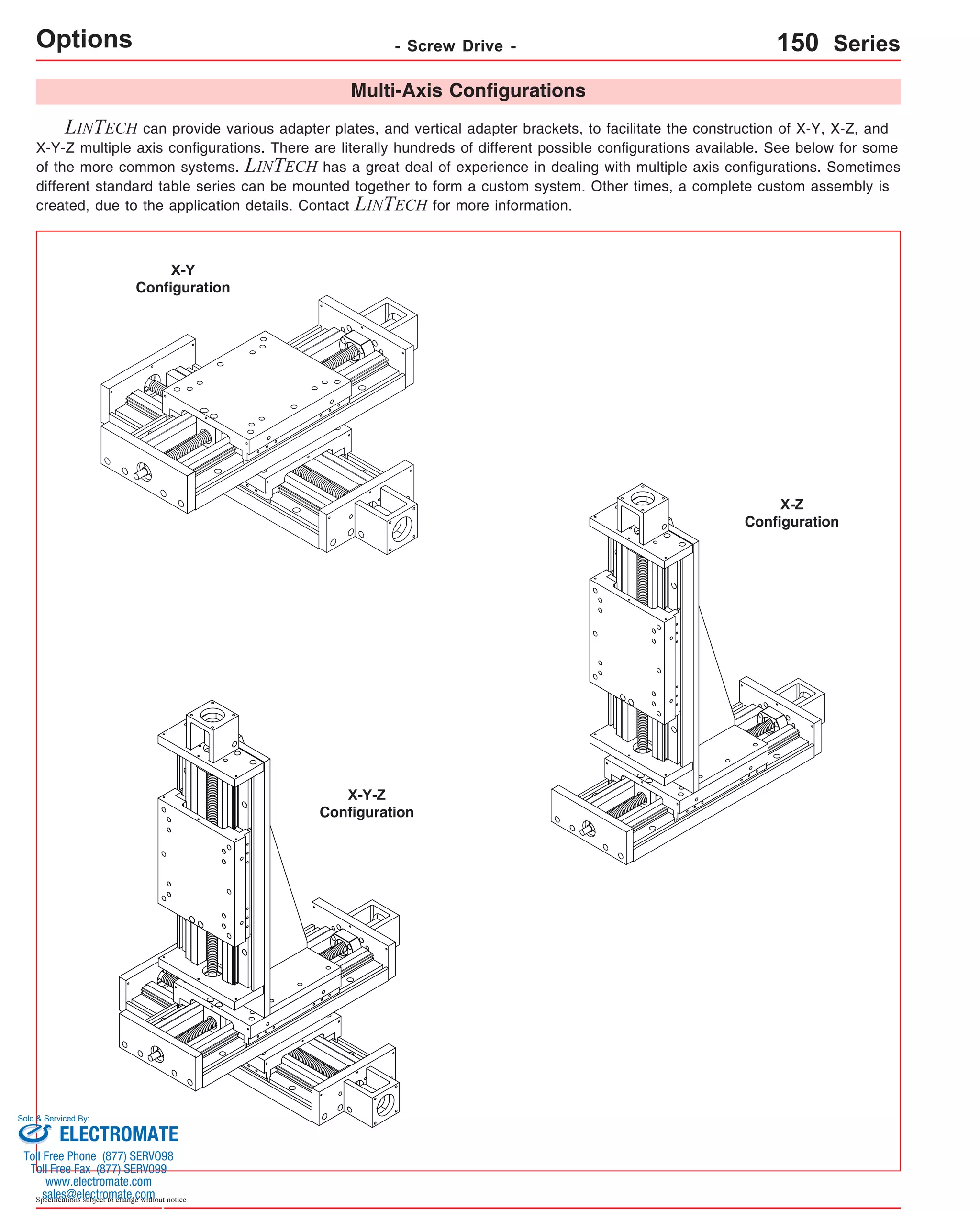
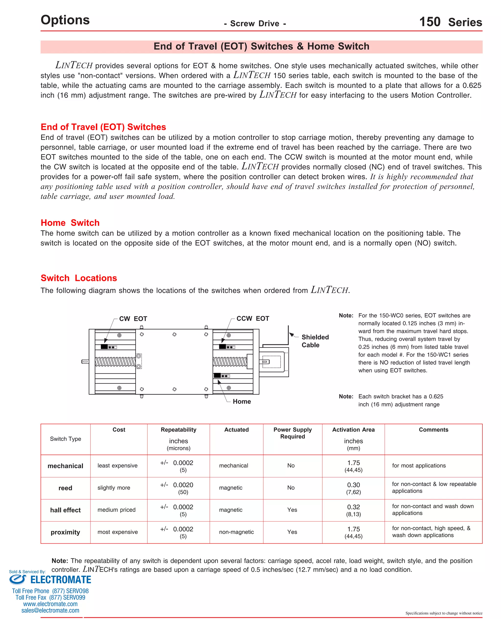

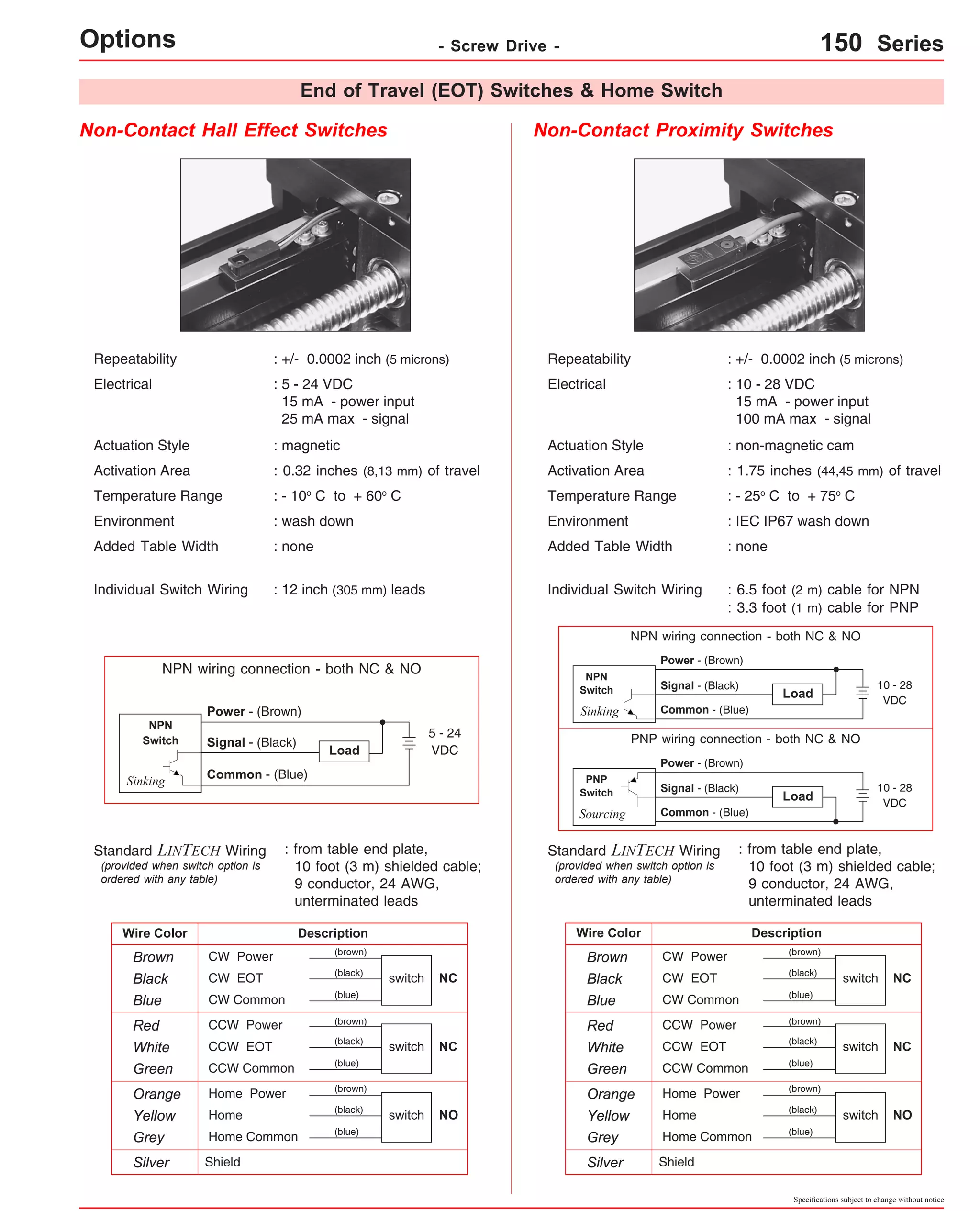

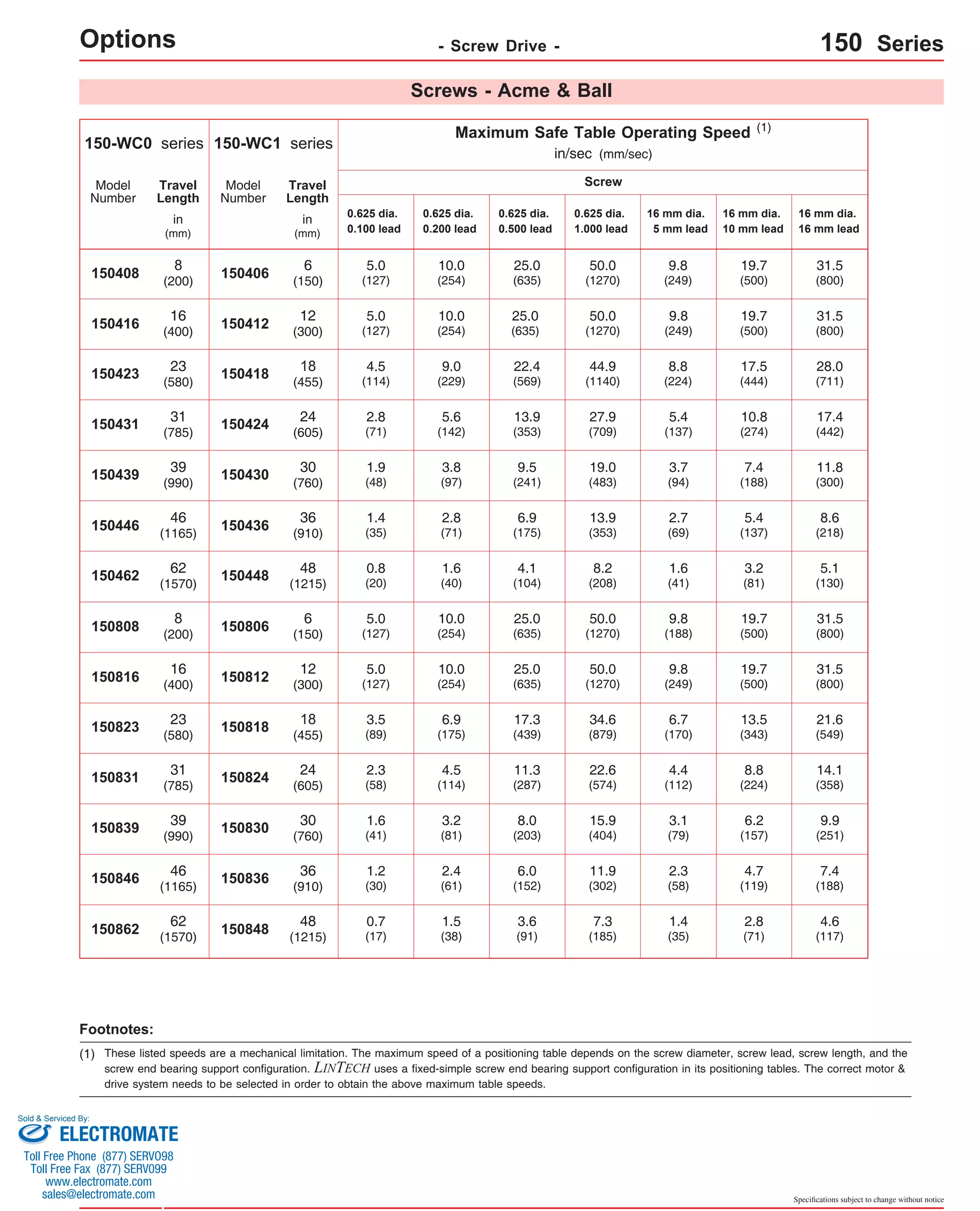
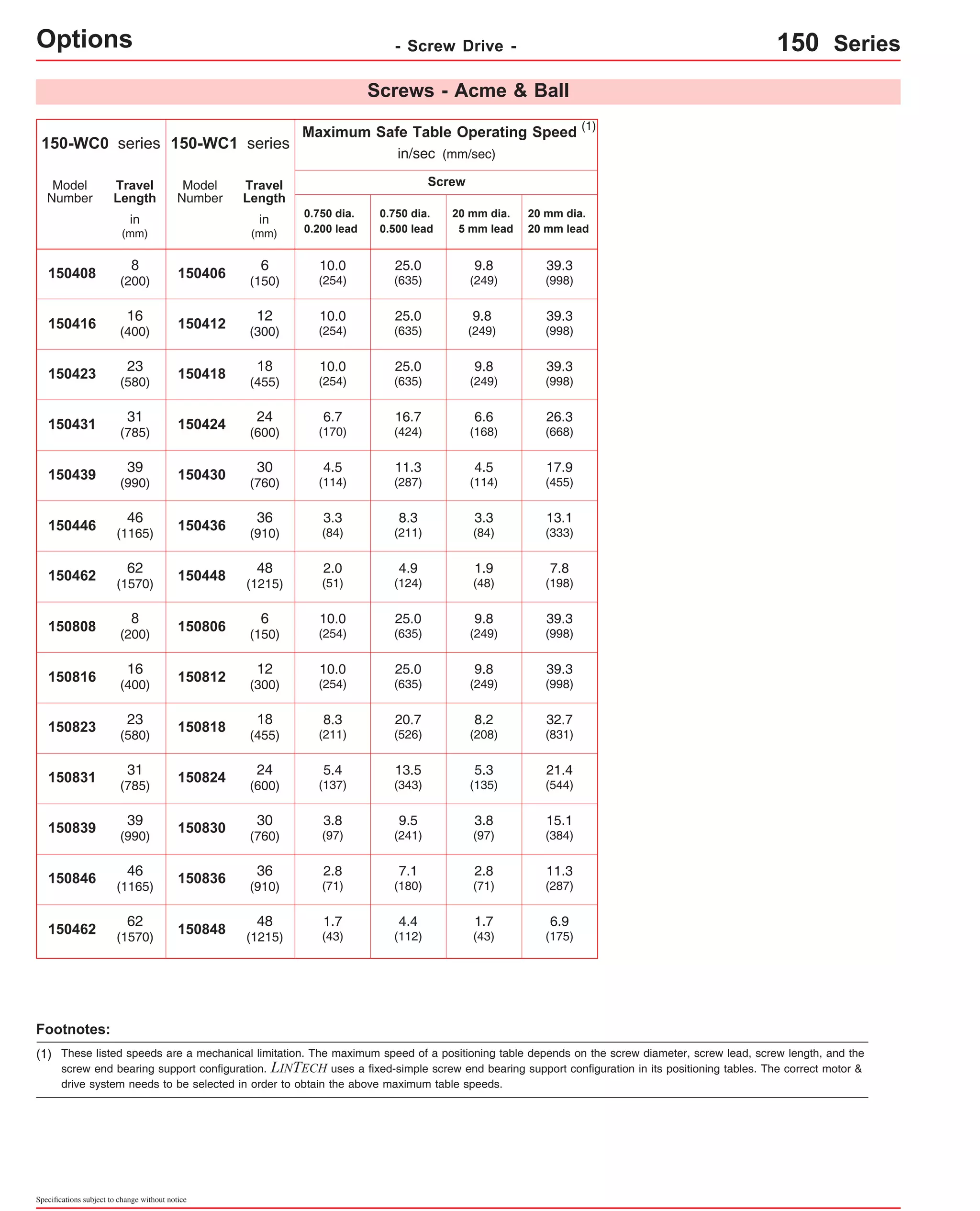
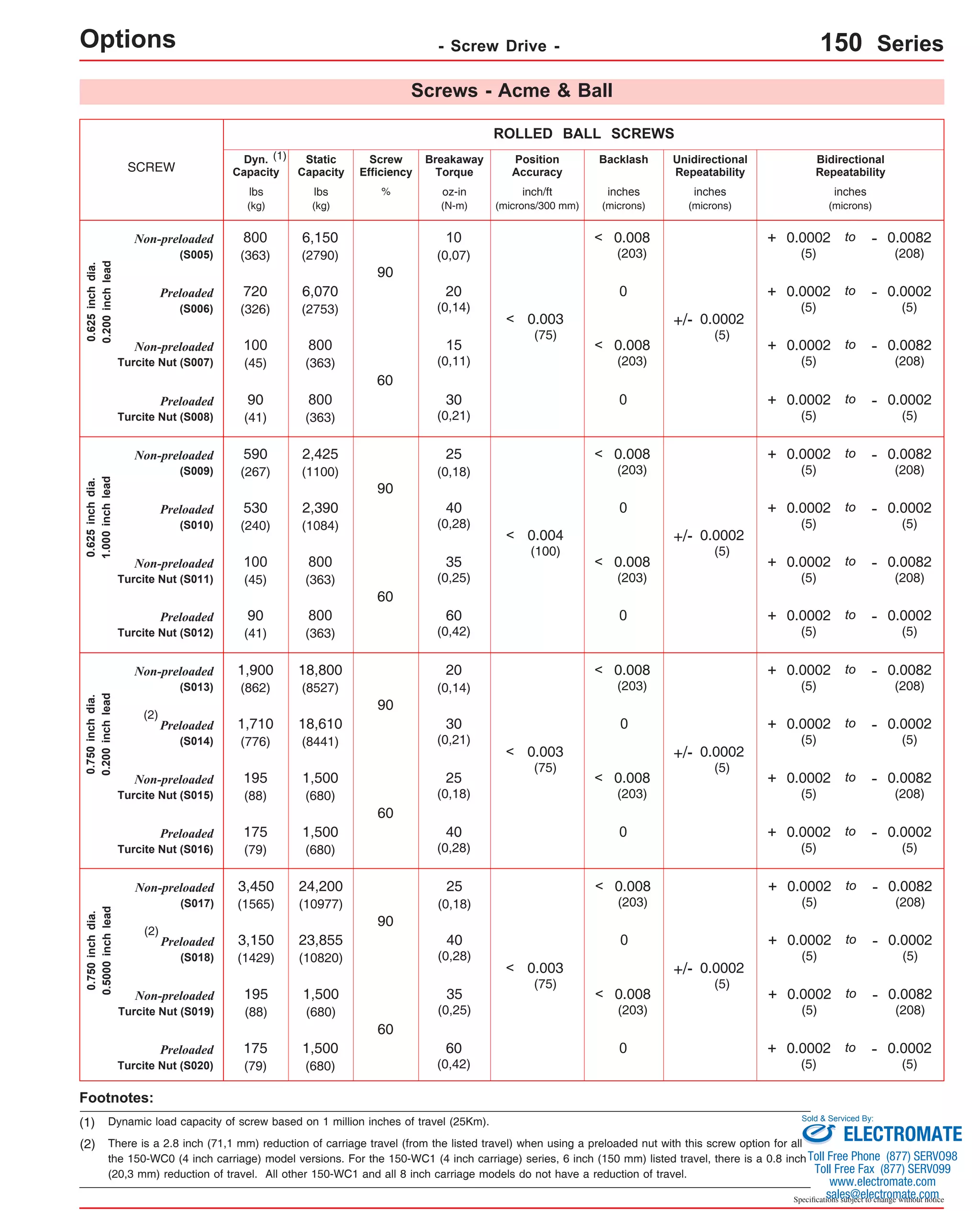
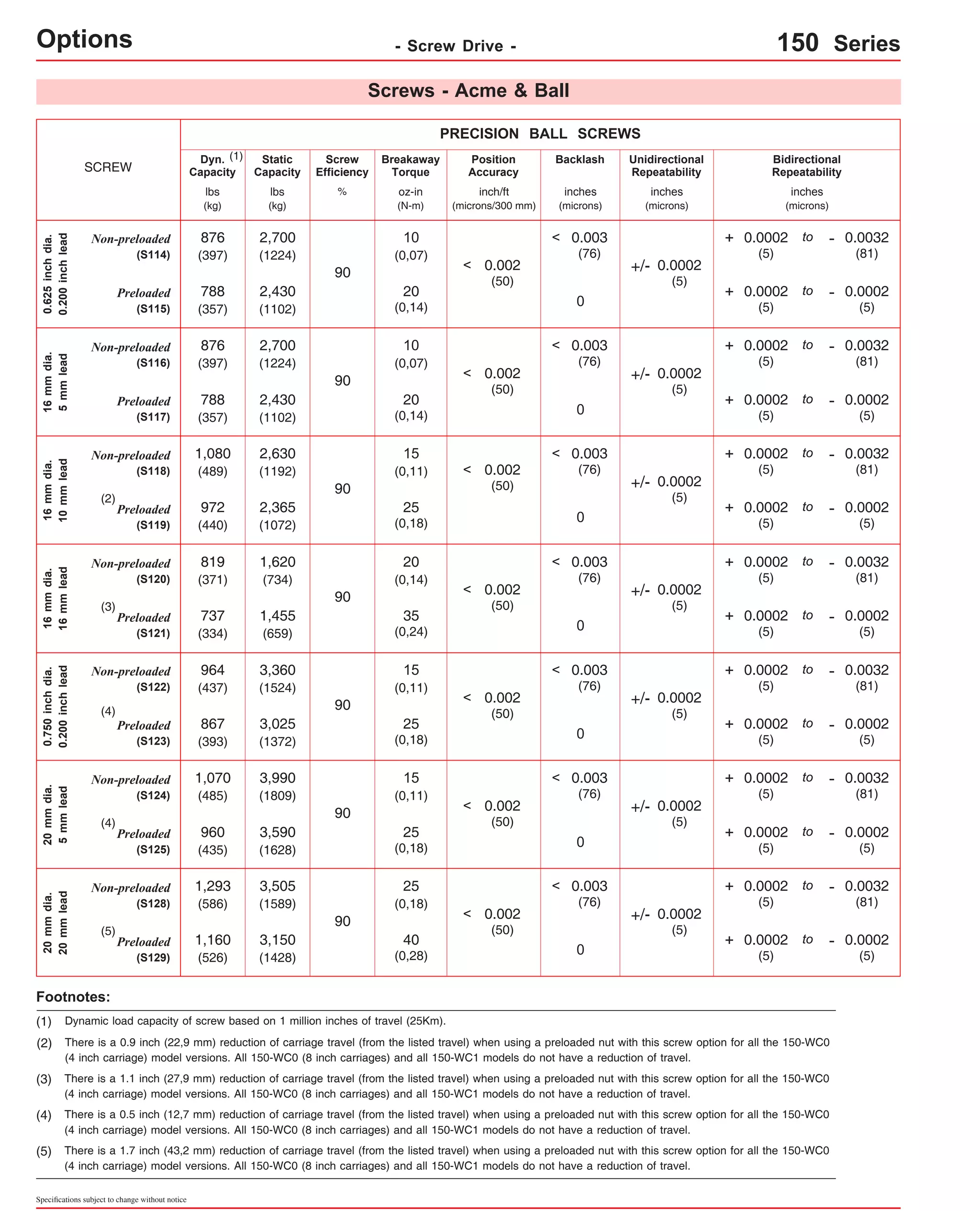

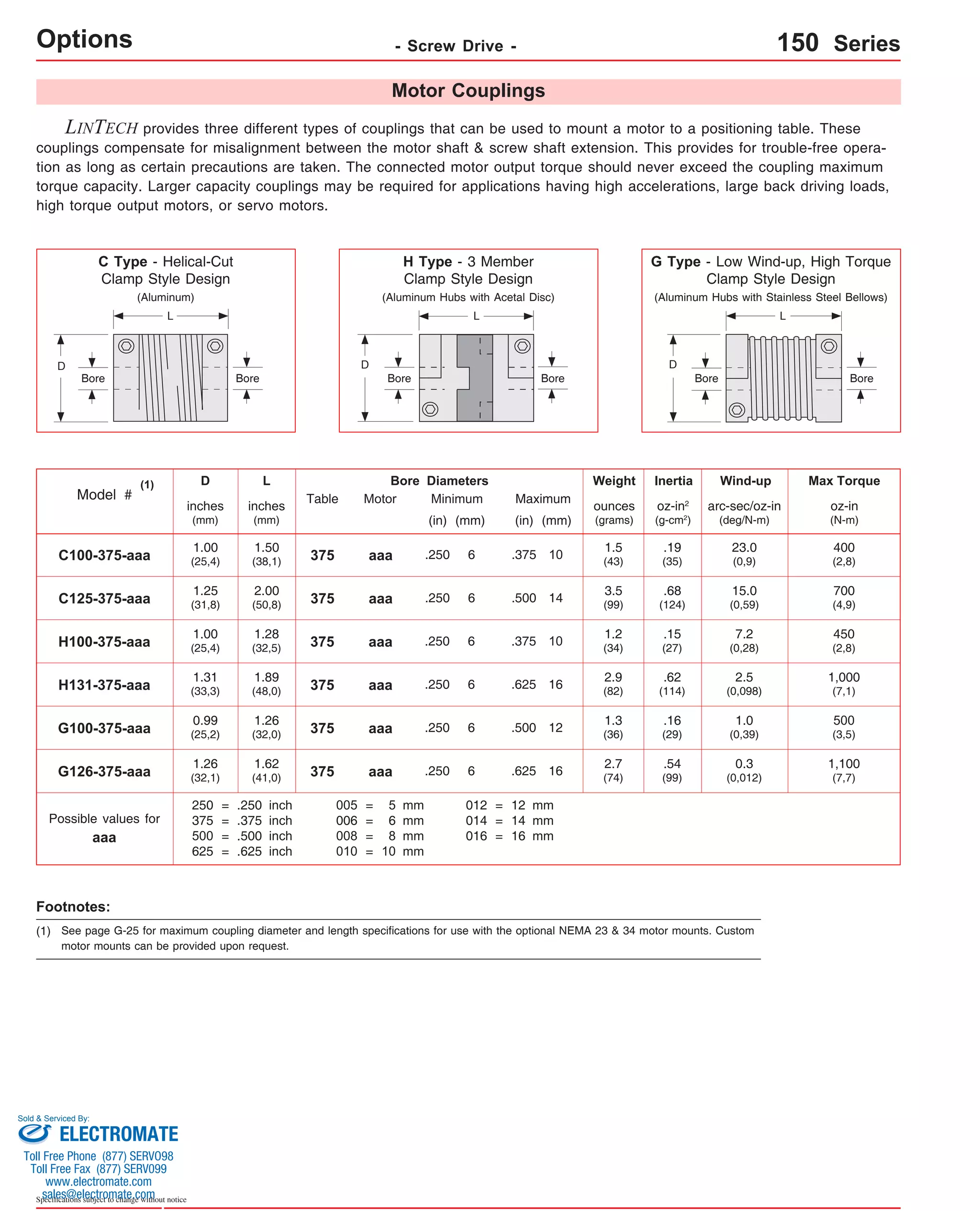
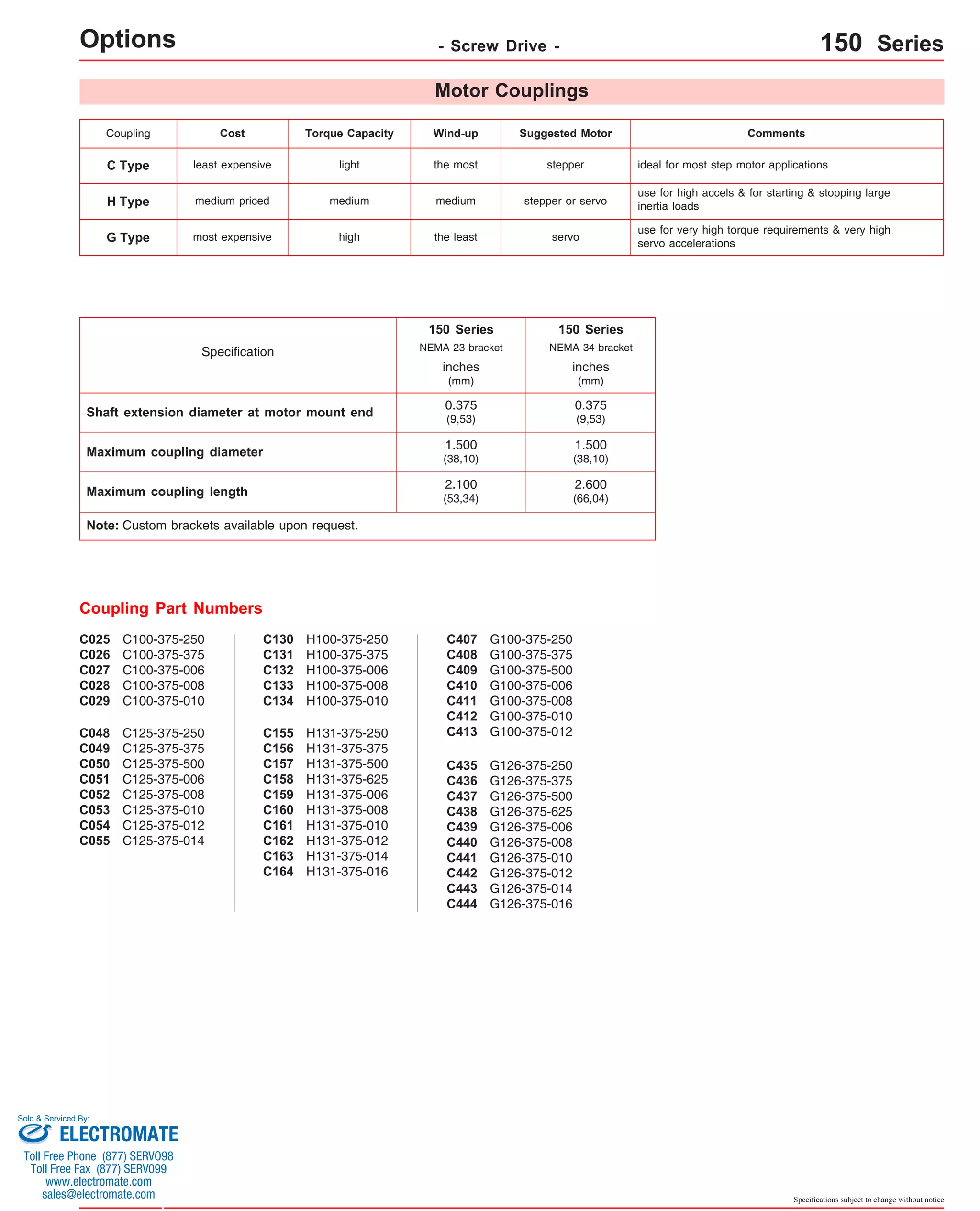
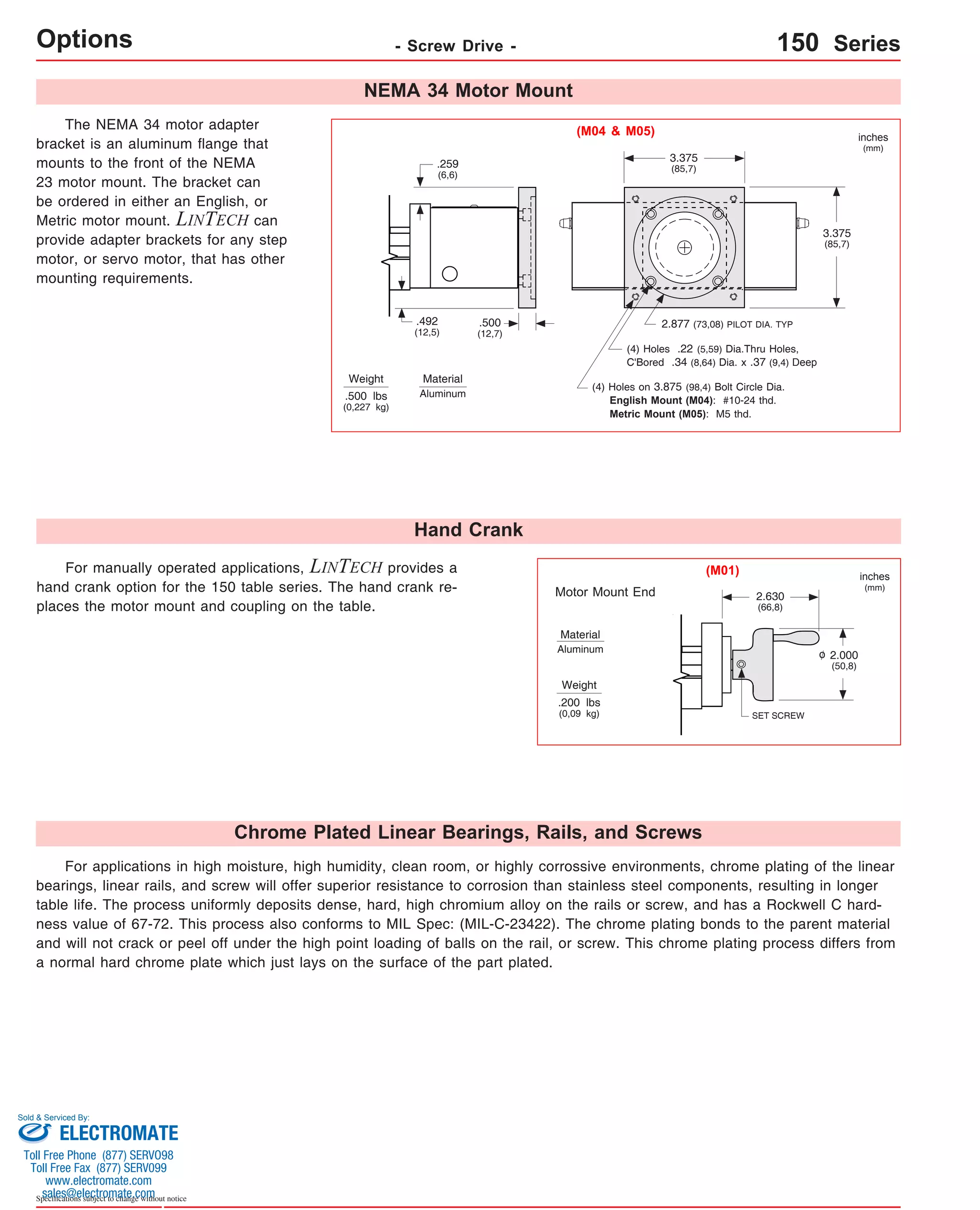
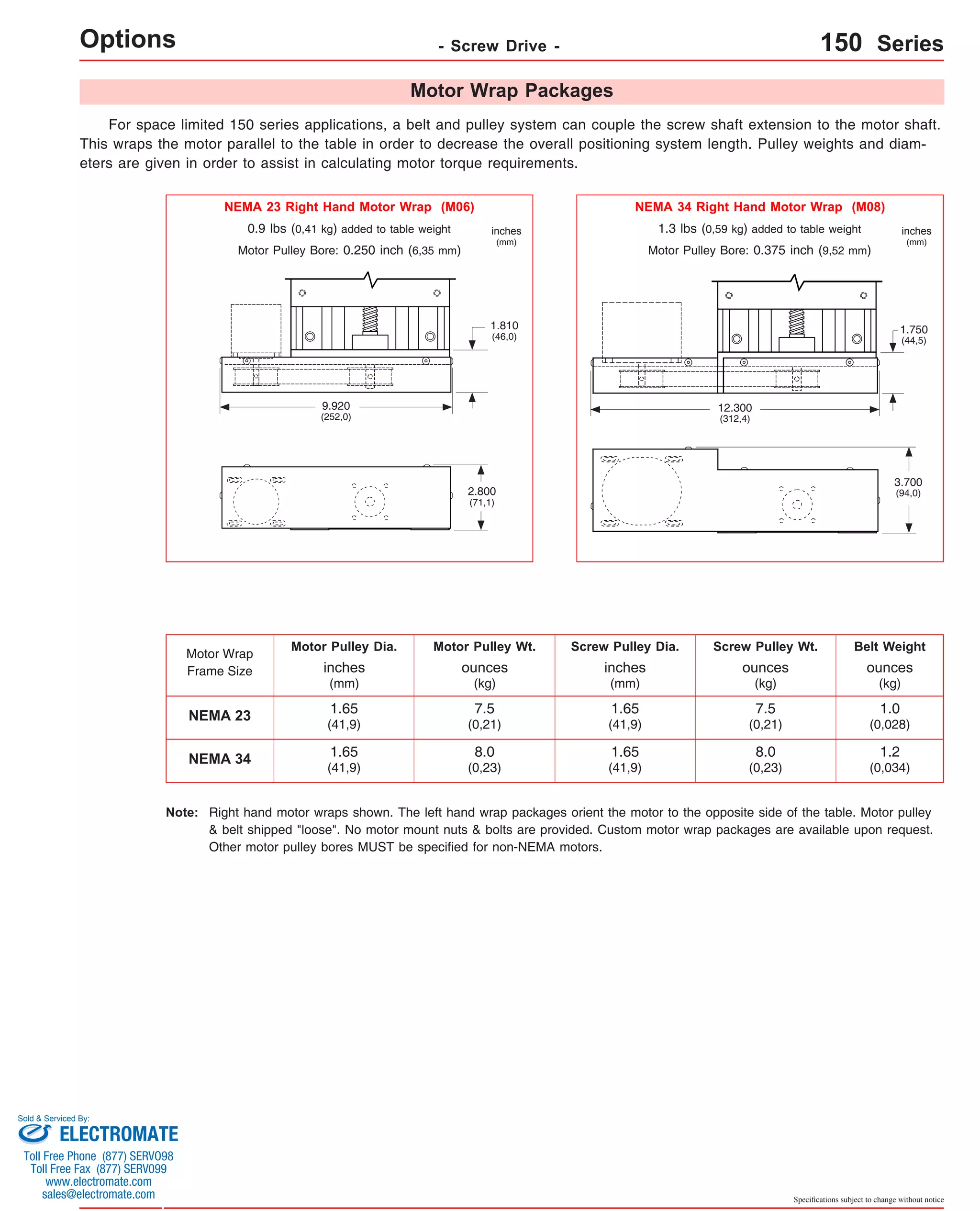
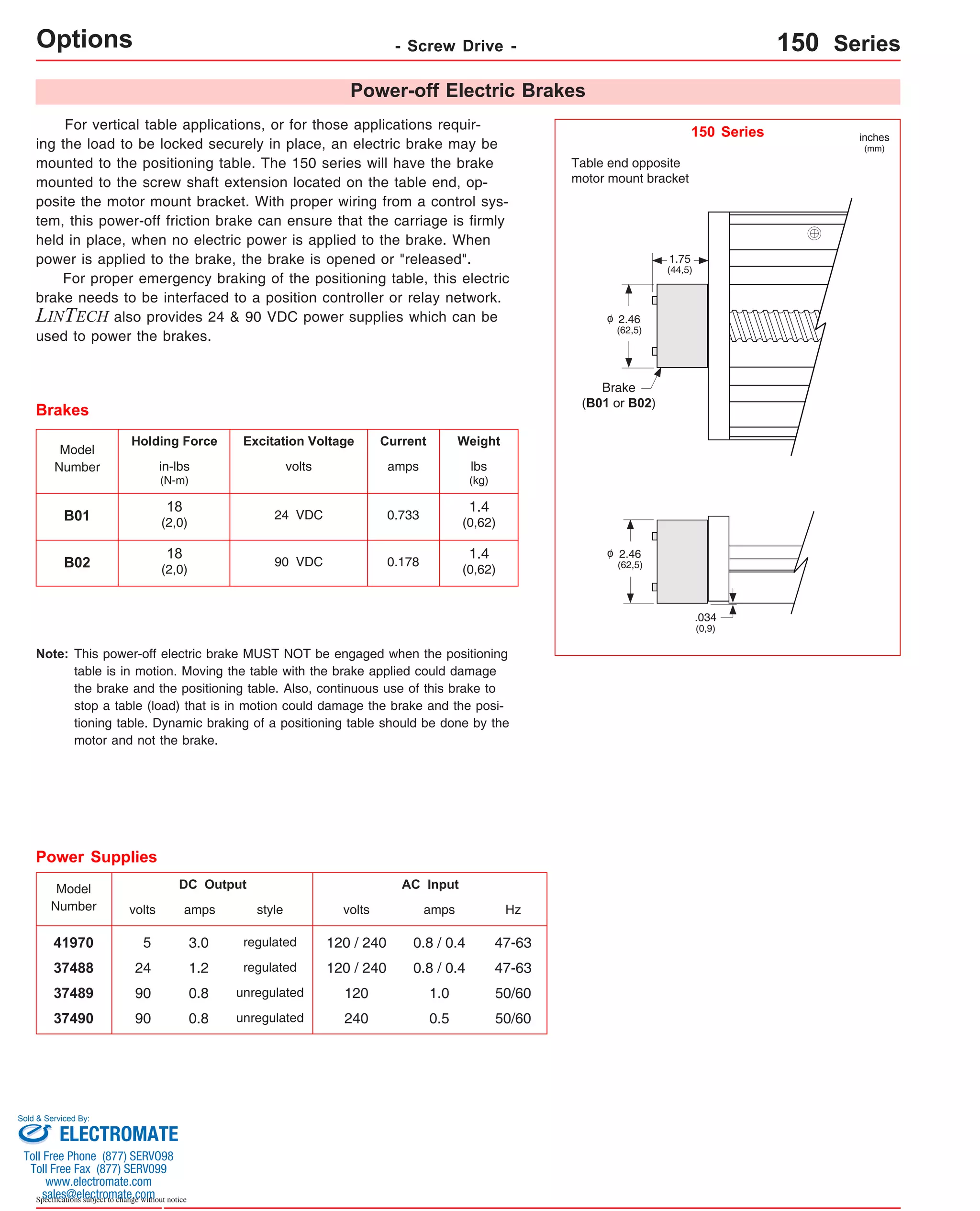
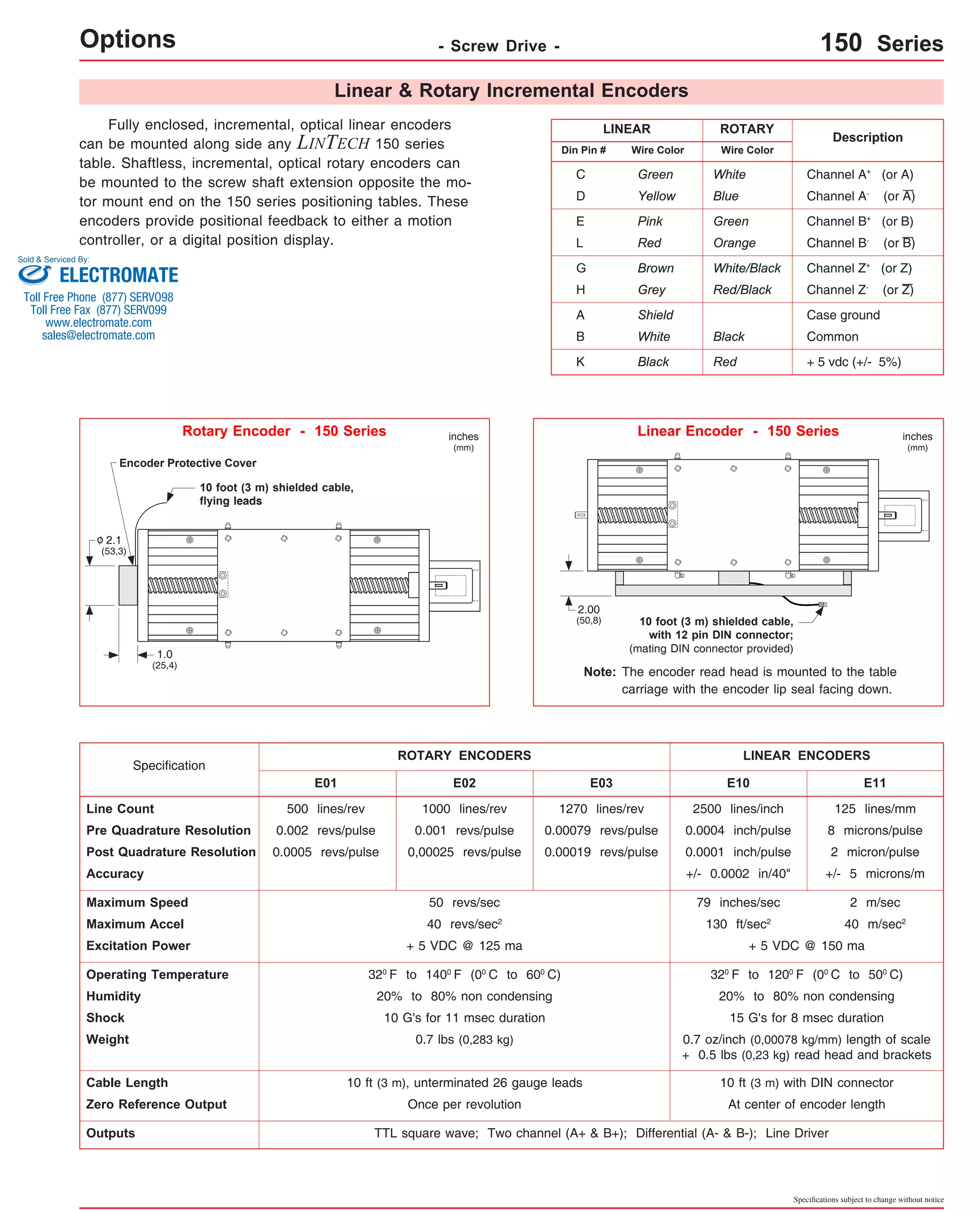

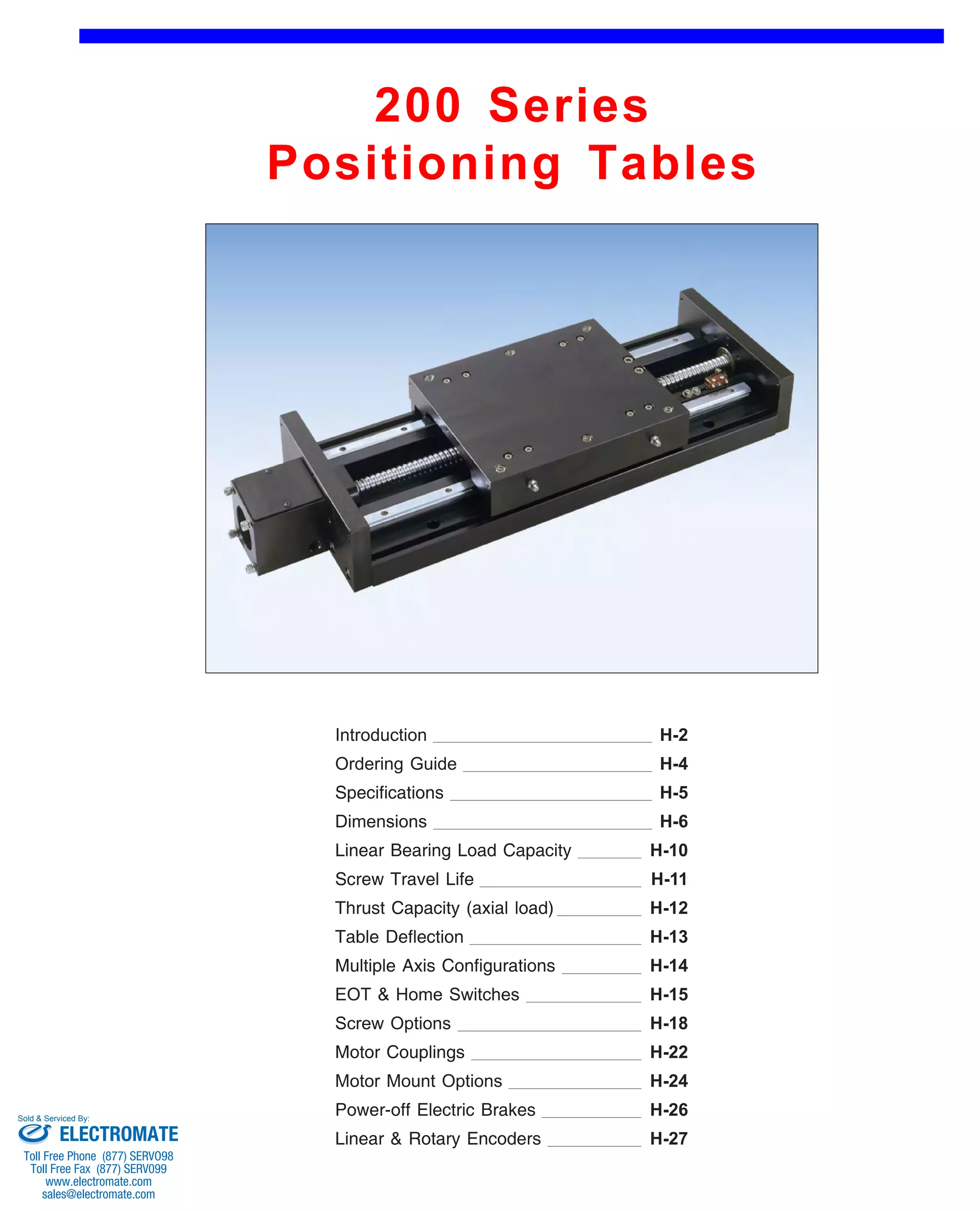

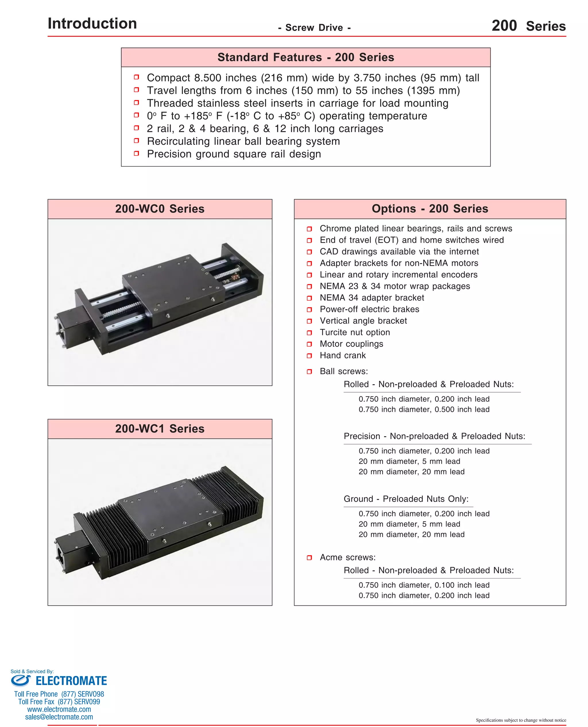

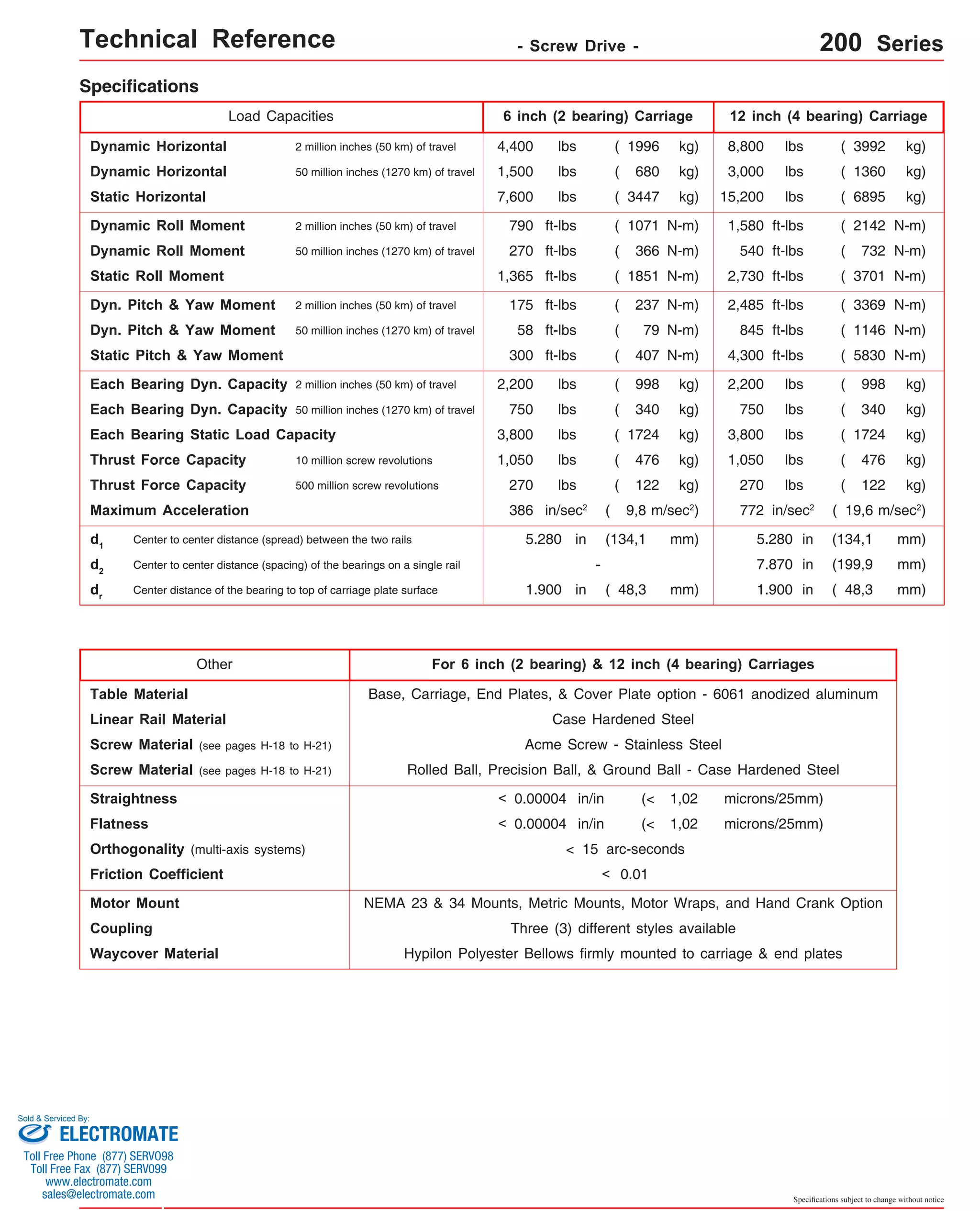
![Technical Reference - Screw Drive - 200-WC0 Series
Travel
Length
Table Dimensions
Model
Number lbs
inches
(mm)
2.000
(50,8) 16 30.12
(765) 21 7
(530)
1.870
(47,5) 20 36.87
(936) 28 9
(710)
1.870
(47,5) 24 43.87
(1114) 35 11
(885)
1.750
(44,4) 28 50.62
(1286) 41 13
(1040)
1.620
(41,1) 36 64.37
(1635) 55 17
(1395)
1.620
(41,1) 12 22.37
(568) 7 5
(175)
1.560
(39,6) 16 29.24
(743) 14 7
(355)
1.500
(38,1) 20 36.12
(917) 21 9
(530)
1.370
(34,8) 24 42.87
(1089) 28 11
(710)
1.120
(28,4) 40 70.37
(1787) 55 19
(1395)
Sold & Serviced By:
Specifications subject to change without notice
(kg)
inches
(mm)
C
inches
(mm)
Mounting Dimensions
A
200607-WC0
14.75
38.3
(374,6)
(17,4) B
17.25
(438,1)
2.120
(53,8)
D M
8
Screw
Length
inches
(mm)
16.37
(416)
Table
Weight
3
200614-WC0 21.62
24.12
2.060
5
12 23.24
47.4
(549,1)
(612,6)
(52,3) (590) (21,5) 7
(175)
14
(355)
200621-WC0 28.50
31.00
56.5
(723,9)
(787,4)
(25,6) Dimensions & Specifications
200628-WC0 35.25
37.75
65.6
(895,3)
(958,8)
(29,8) 200635-WC0 42.25
44.75
74.7
(1073,1)
(1136,6)
(33,9) 200641-WC0 49.00
51.50
83.8
(1244,6)
(1308,1)
(38,0) 200655-WC0 62.75
65.25
100.0
(1593,8)
(1657,3)
(45,4) 201207-WC0 20.75
23.25
54.3
(527,0)
(590,5)
(24,6) 201214-WC0 27.62
30.12
63.4
(701,5)
(765,0)
(28,8) 201221-WC0 34.50
37.00
72.5
(876,3)
(939,8)
(32,9) 201228-WC0 41.25
43.75
81.6
(1047,7)
(1111,2)
(37,0) 90.7
50.75
(1289,0)
1.370
(34,8) 28 49.87
201235-WC0 35
48.25
(885)
(1225,5)
13 (1267) (41,1) 201241-WC0 41 55.00
57.50
1.250
15
32 56.62
99.8
(1040)
(1397,0)
(1460,5)
(31,7)
(1438)
(45,3) 201255-WC0 68.75
71.25
117.0
(1746,2)
(1809,7)
(53,1) - Without Waycovers -
06 = 6 inch (152,4 mm) carriage length; 2 bearings; carriage weight = 11.0 lbs. (4,99 kg)
12 = 12 inch (304,8 mm) carriage length; 4 bearings; carriage weight = 19.0 lbs. (8,62 kg)
Footnotes:
(1)
(1)
Weight shown is with a 0.750 inch (20 mm) diameter screw, a NEMA 23 motor mount [0.34 lbs (0,16 kg)], and a C125 style [0.22 lbs (0,10 kg)] coupling.
version: 01/2014
ELECTROMATE
Toll Free Phone (877) SERVO98
Toll Free Fax (877) SERV099
www.electromate.com
sales@electromate.com](https://image.slidesharecdn.com/lintechpositioningsystemscatalog-141018113223-conversion-gate01/75/Lintech-positioning-systems_catalog-291-2048.jpg)
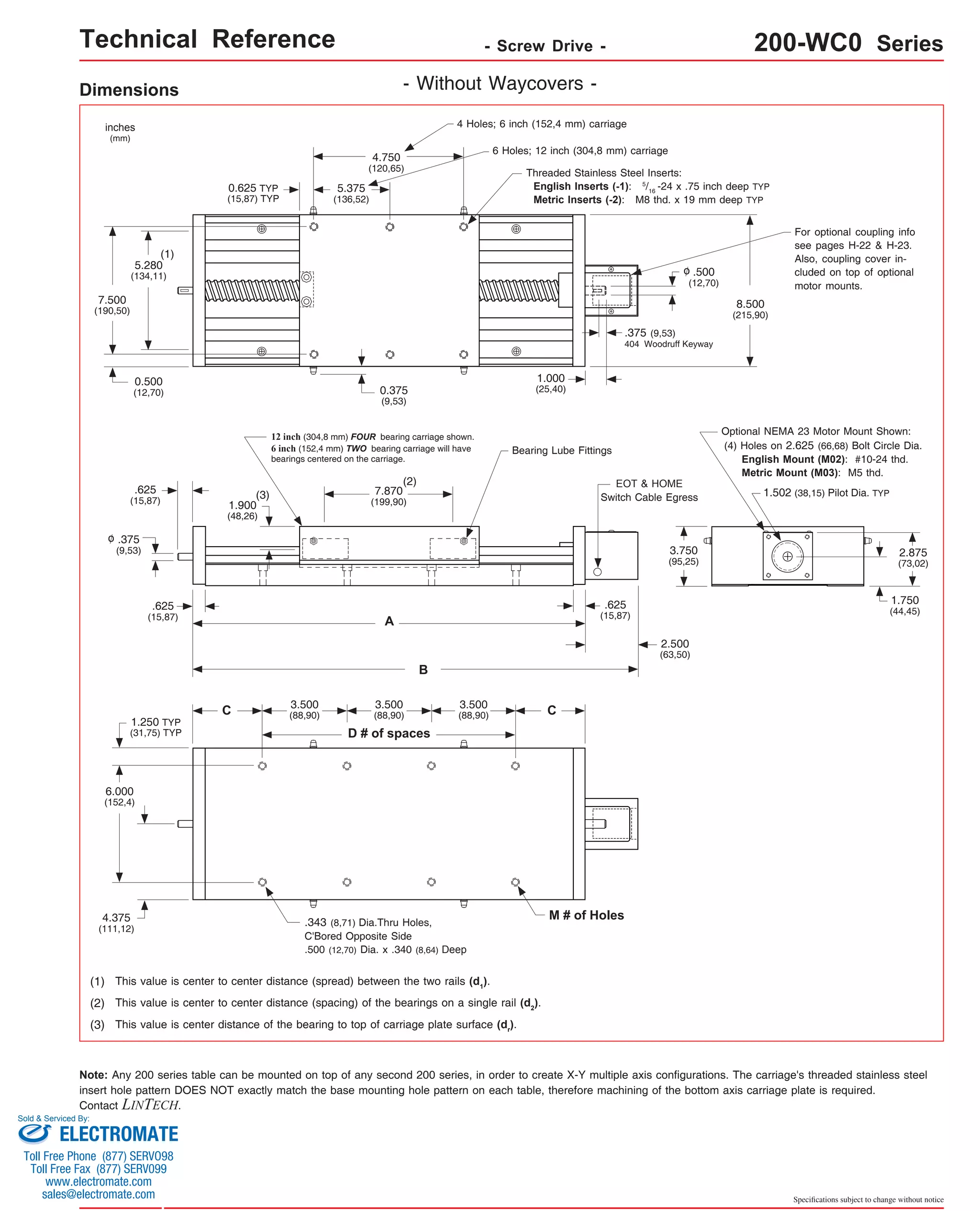
![Technical Reference - Screw Drive - 200-WC1 Series
Travel
Length
Table Dimensions
Model
Number lbs
inches
(mm)
2.000
(50,8) 18 7 16
(455)
1.870
(47,5) 24 9 20
(605)
1.870
(47,5) 30 11 24
(760)
1.750
(44,4) 36 13 28
(910)
1.620
(41,1) 48 17 36
(1215)
1.620
(41,1) 6 5 12
(150)
1.560
(39,6) 12 7 16
(300)
1.500
(38,1) 18 9 20
(455)
1.370
(34,8) 24 11 24
(605)
1.370
(34,8) 13 28 30
(760)
36 15 32
(910)
1.120
(28,4) 48 19 40
(1215)
Sold & Serviced By:
Specifications subject to change without notice
(kg)
inches
(mm)
C
inches
(mm)
Mounting Dimensions
A
200606-WC1
14.75
40.0
(374,6)
(18,1) B
17.25
(438,1)
2.120
(53,8)
D M
8
Screw
Length
inches
(mm)
Table
Weight
3
16.37
(416)
23.24
(590)
30.12
(765)
36.87
(936)
43.87
(1114)
50.62
(1286)
64.37
(1635)
22.37
(568)
29.24
(743)
36.12
(917)
42.87
(1089)
49.87
(1267)
56.62
(1438)
70.37
(1787)
200612-WC1 21.62
24.12
2.060
5 12
50.0
(549,1)
(612,6)
(52,3) (22,7) 6
(150)
12
(300)
200618-WC1 28.50
31.00
60.0
(723,9)
(787,4)
(27,2) Dimensions & Specifications
200624-WC1 35.25
37.75
70.0
(895,3)
(958,8)
(31,8) 200630-WC1 42.25
44.75
80.0
(1073,1)
(1136,6)
(36,3) 200636-WC1 49.00
51.50
90.0
(1244,6)
(1308,1)
(40,8) 200648-WC1 62.75
65.25
108.0
(1593,8)
(1657,3)
(49,0) 201206-WC1 20.75
23.25
56.0
(527,0)
(590,5)
(25,4) 201212-WC1 27.62
30.12
66.0
(701,5)
(765,0)
(29,9) 201218-WC1 34.50
37.00
76.0
(876,3)
(939,8)
(34,5) 201224-WC1 41.25
43.75
86.0
(1047,7)
(1111,2)
(39,0) 96.0
50.75
(1289,0)
201230-WC1 (43,6) 48.25
(1225,5)
201236-WC1 55.00
57.50
1.250
106.0
(1397,0)
(1460,5)
(31,7)
(48,1) 201248-WC1 68.75
71.25
125.0
(1746,2)
(1809,7)
(56,7) - With Waycovers -
(1)
06 = 6 inch (152,4 mm) carriage length; 2 bearings; carriage weight = 11.0 lbs. (4,99 kg)
12 = 12 inch (304,8 mm) carriage length; 4 bearings; carriage weight = 19.0 lbs. (8,62 kg)
Footnotes:
(1) Weight shown is with a 0.750 inch (20 mm) diameter screw, a NEMA 23 motor mount [0.34 lbs (0,16 kg)], and a C125 style [0.22 lbs (0,10 kg)] coupling.
ELECTROMATE
Toll Free Phone (877) SERVO98
Toll Free Fax (877) SERV099
www.electromate.com
sales@electromate.com](https://image.slidesharecdn.com/lintechpositioningsystemscatalog-141018113223-conversion-gate01/75/Lintech-positioning-systems_catalog-293-2048.jpg)
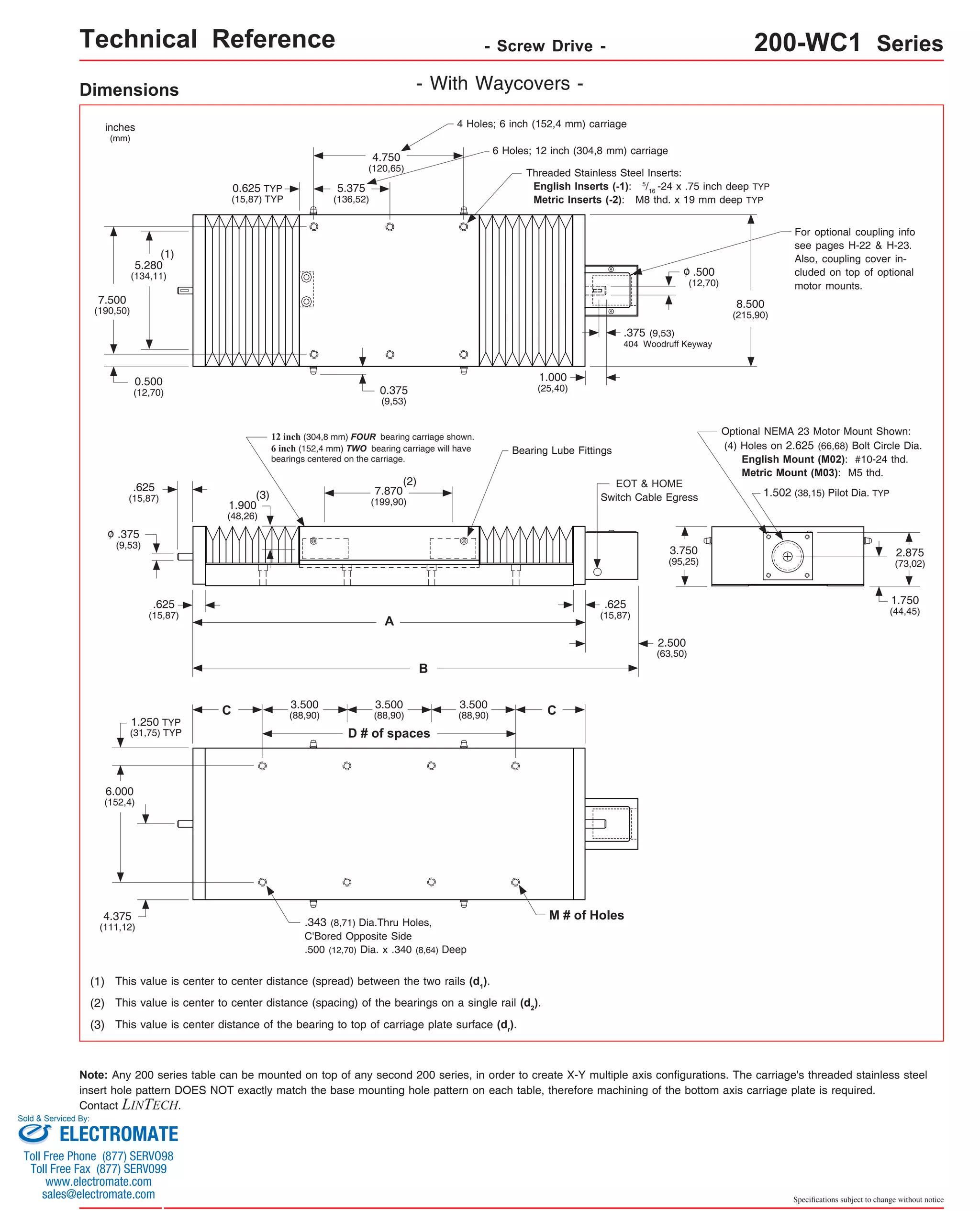
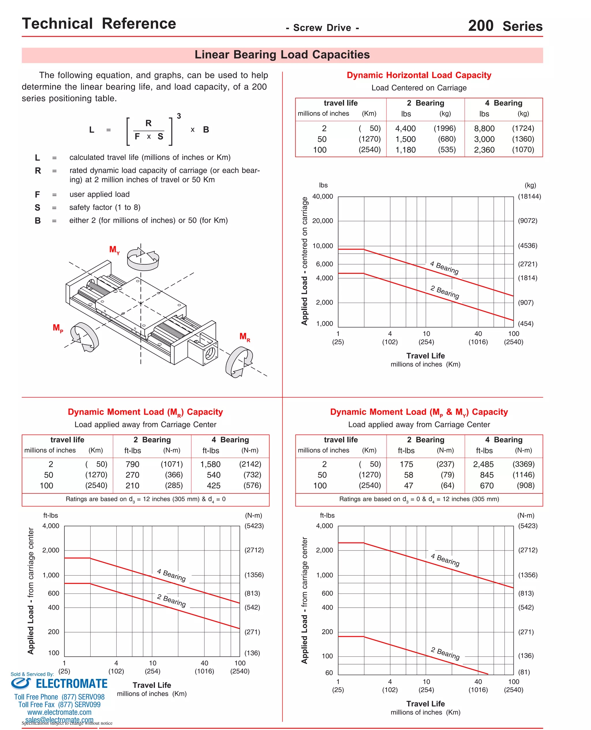
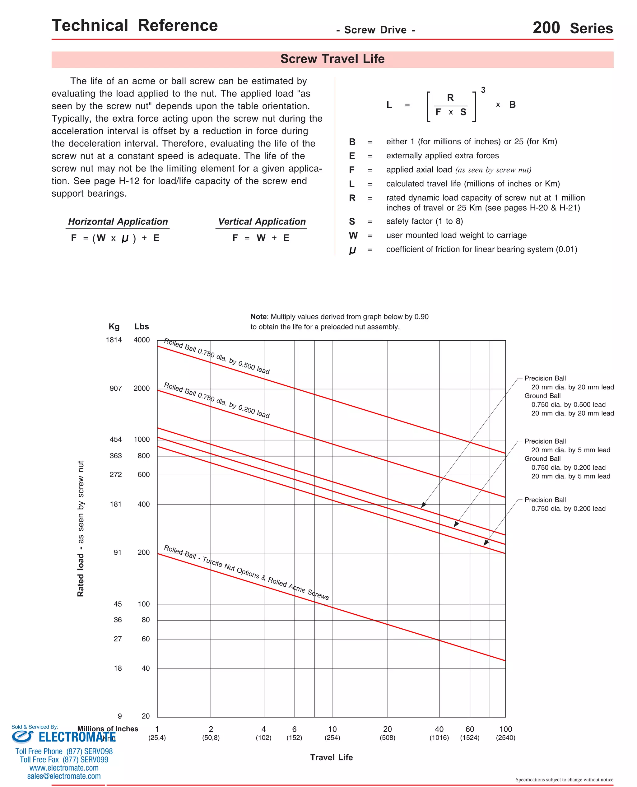
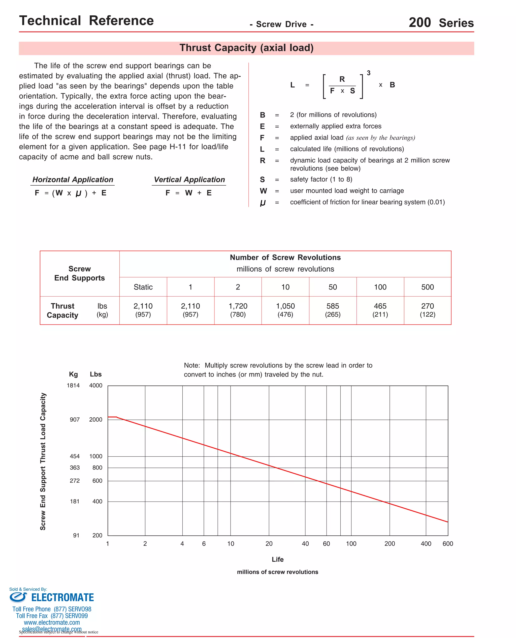


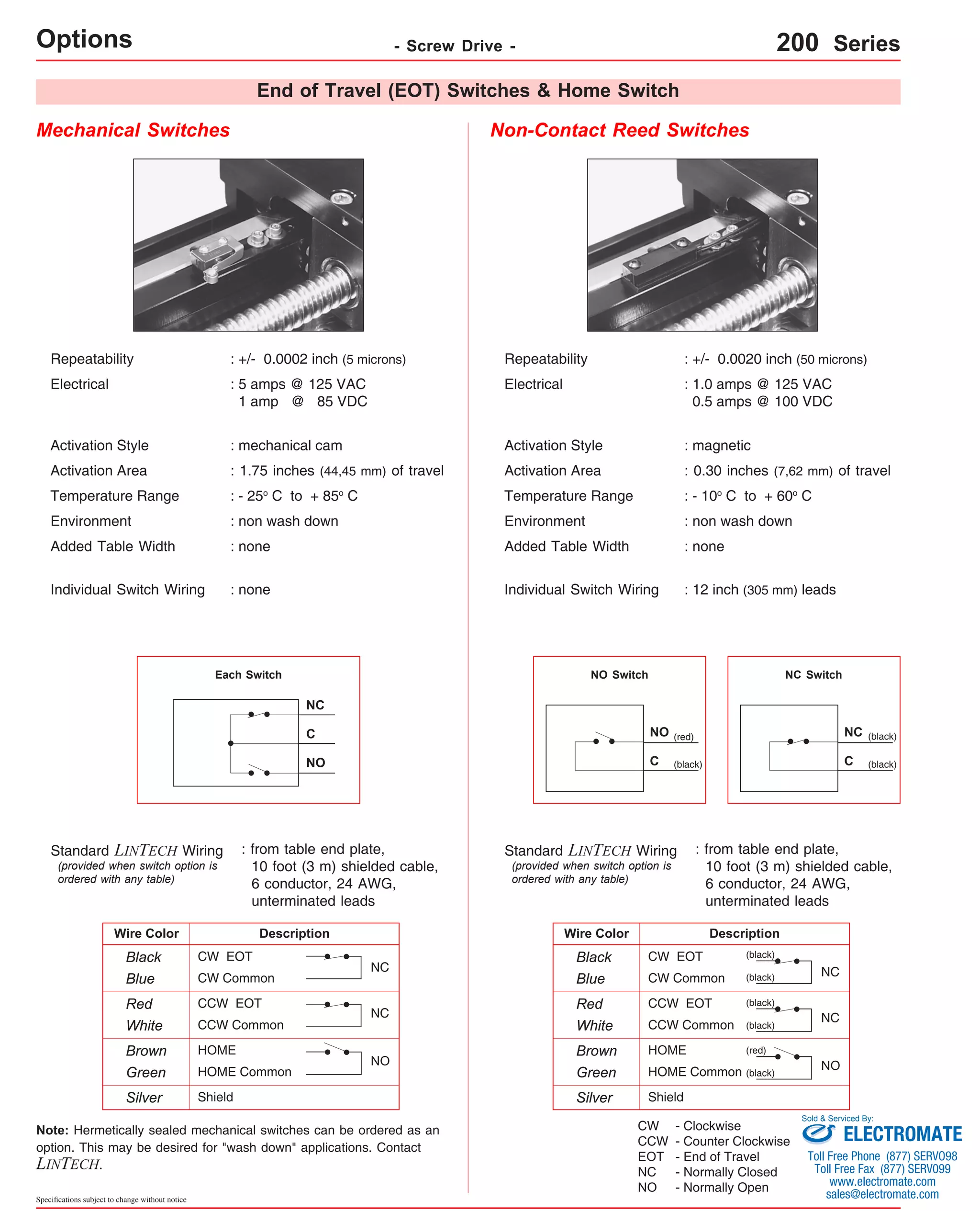

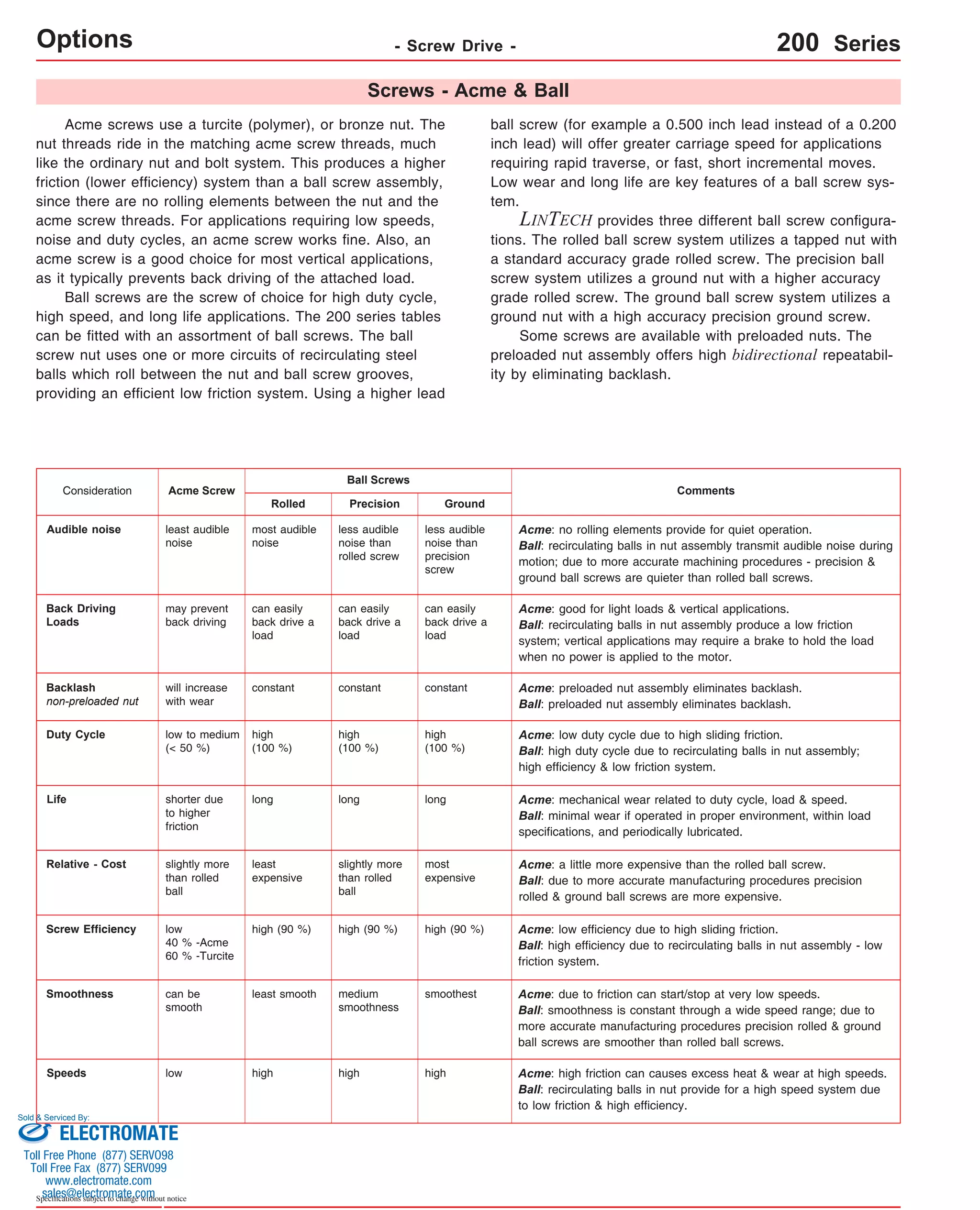
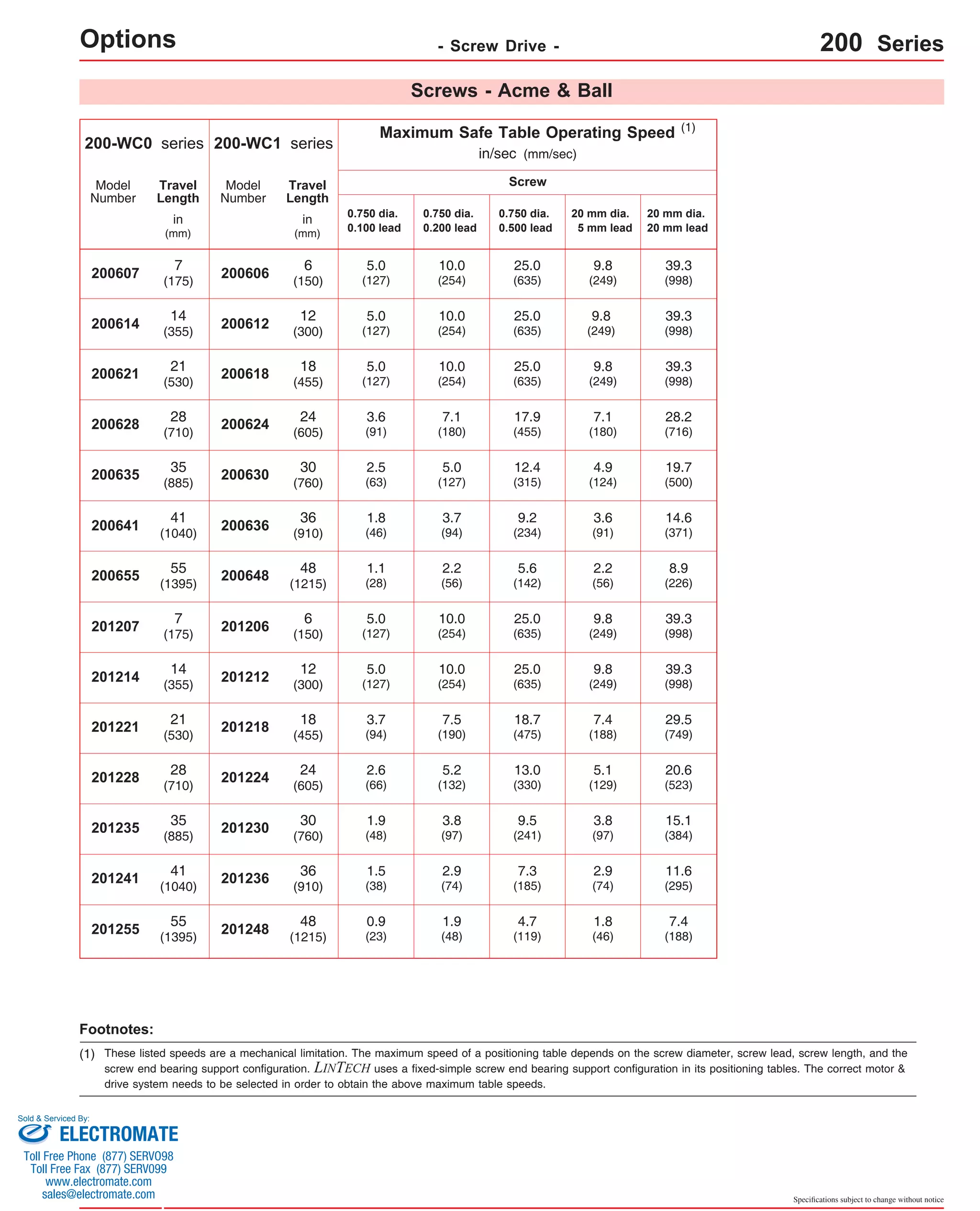
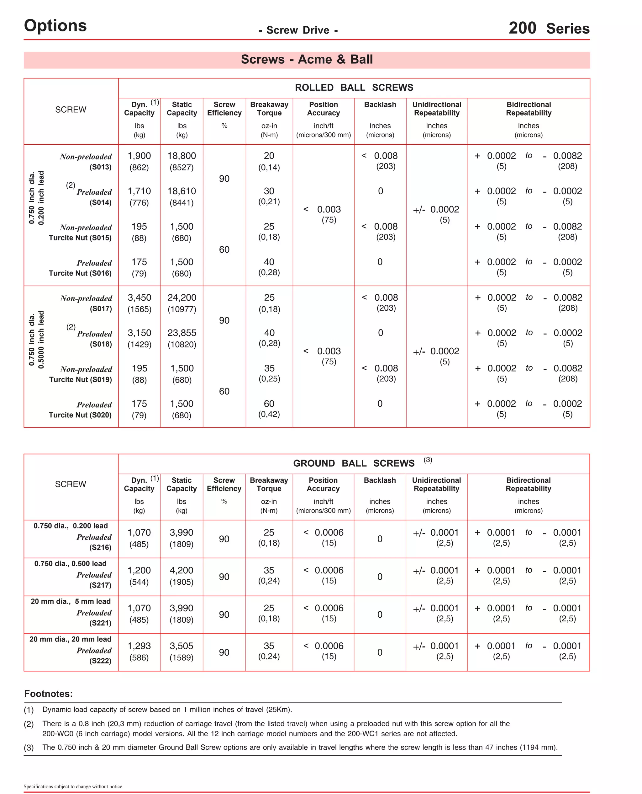
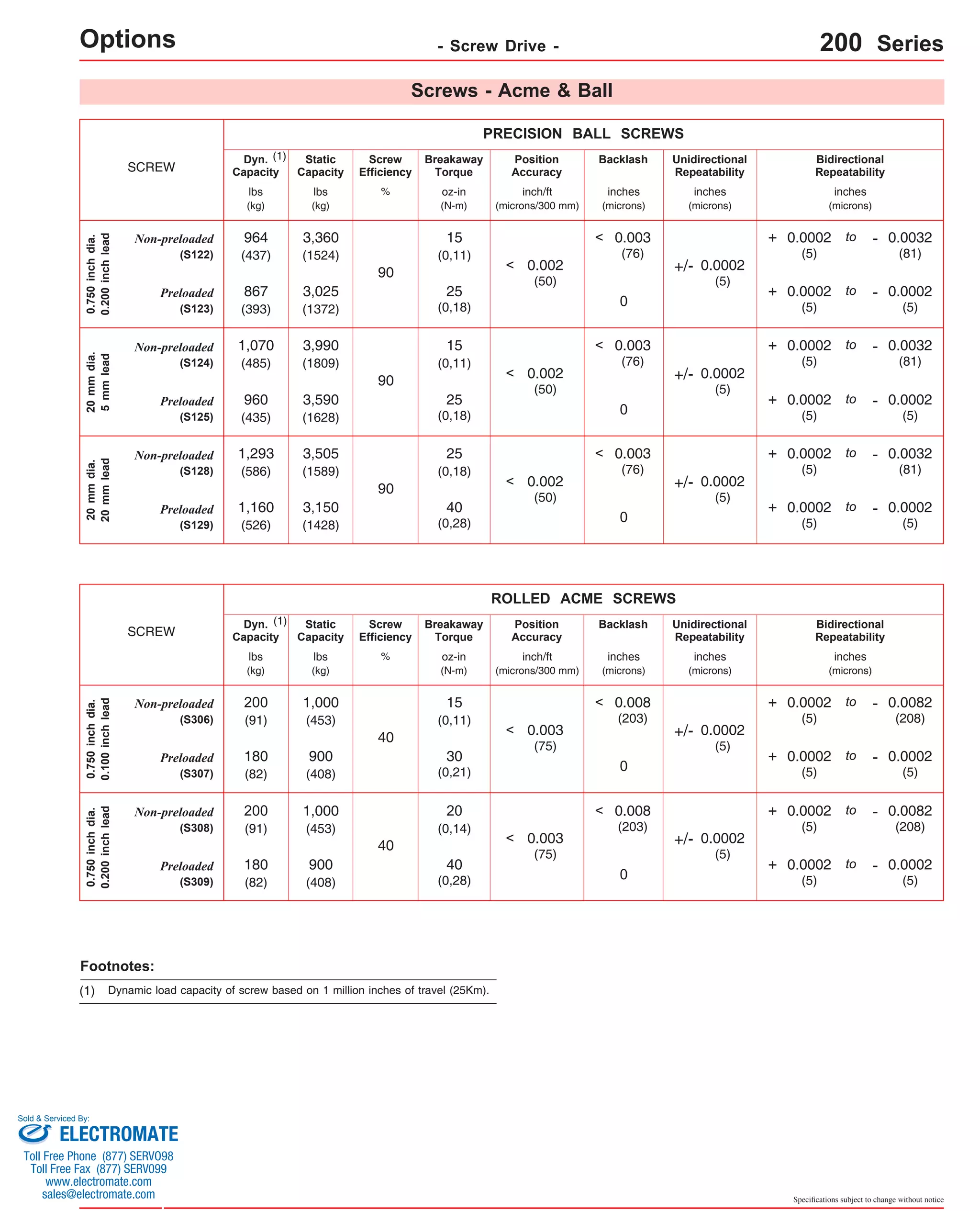
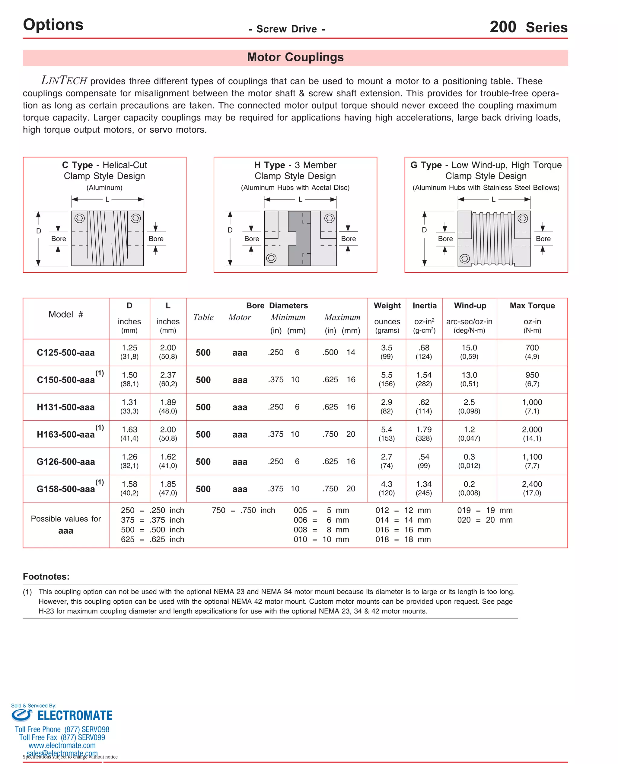


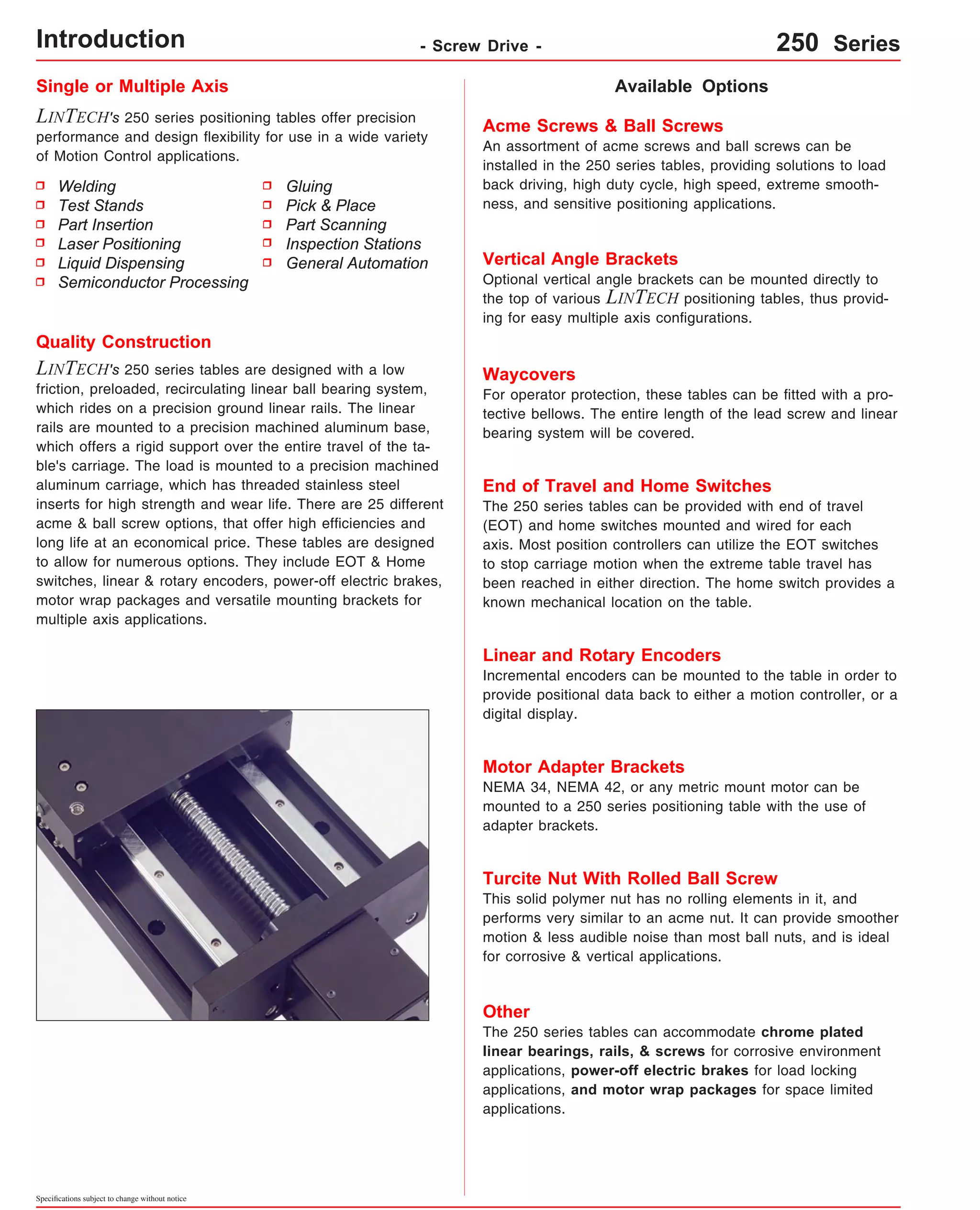
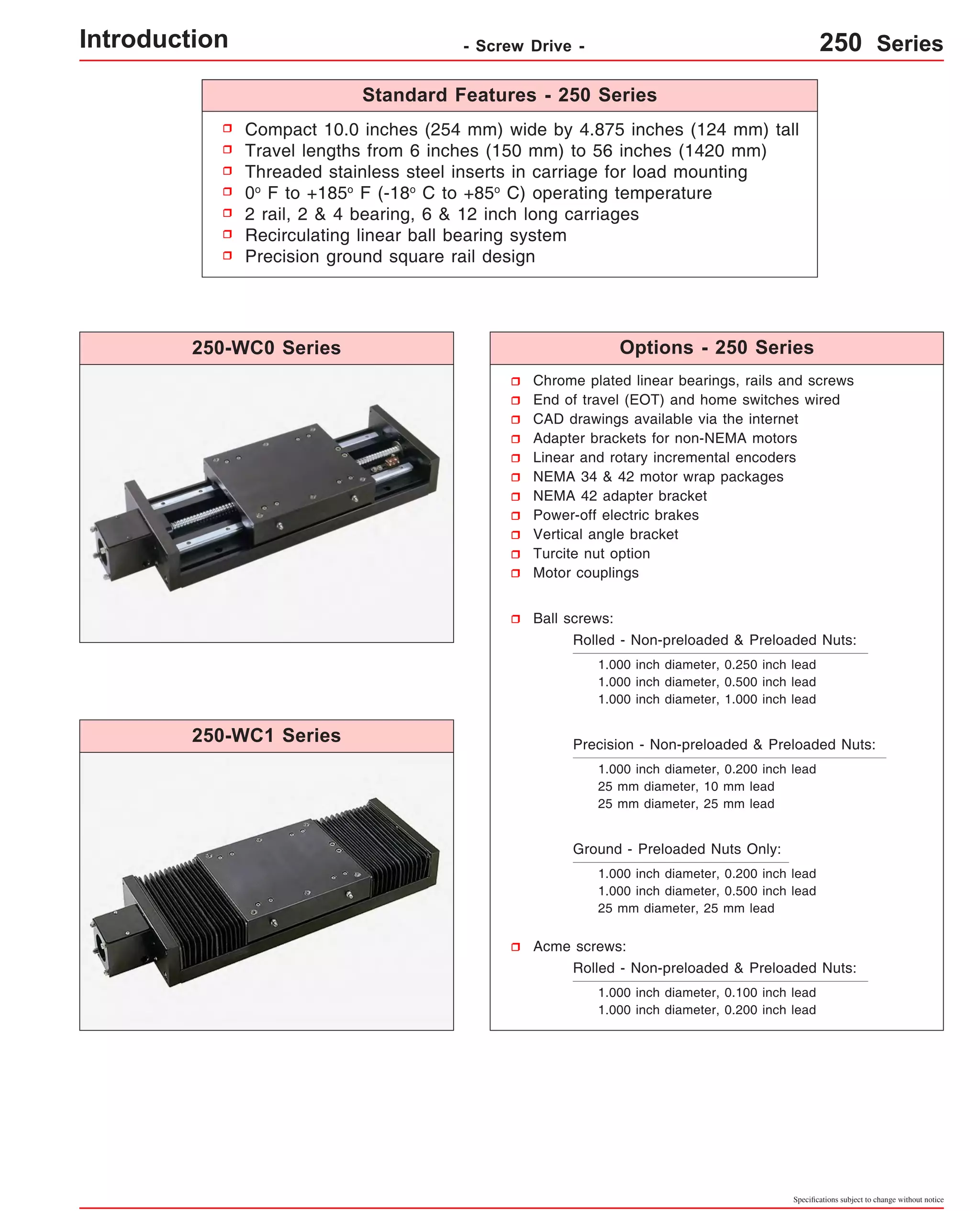
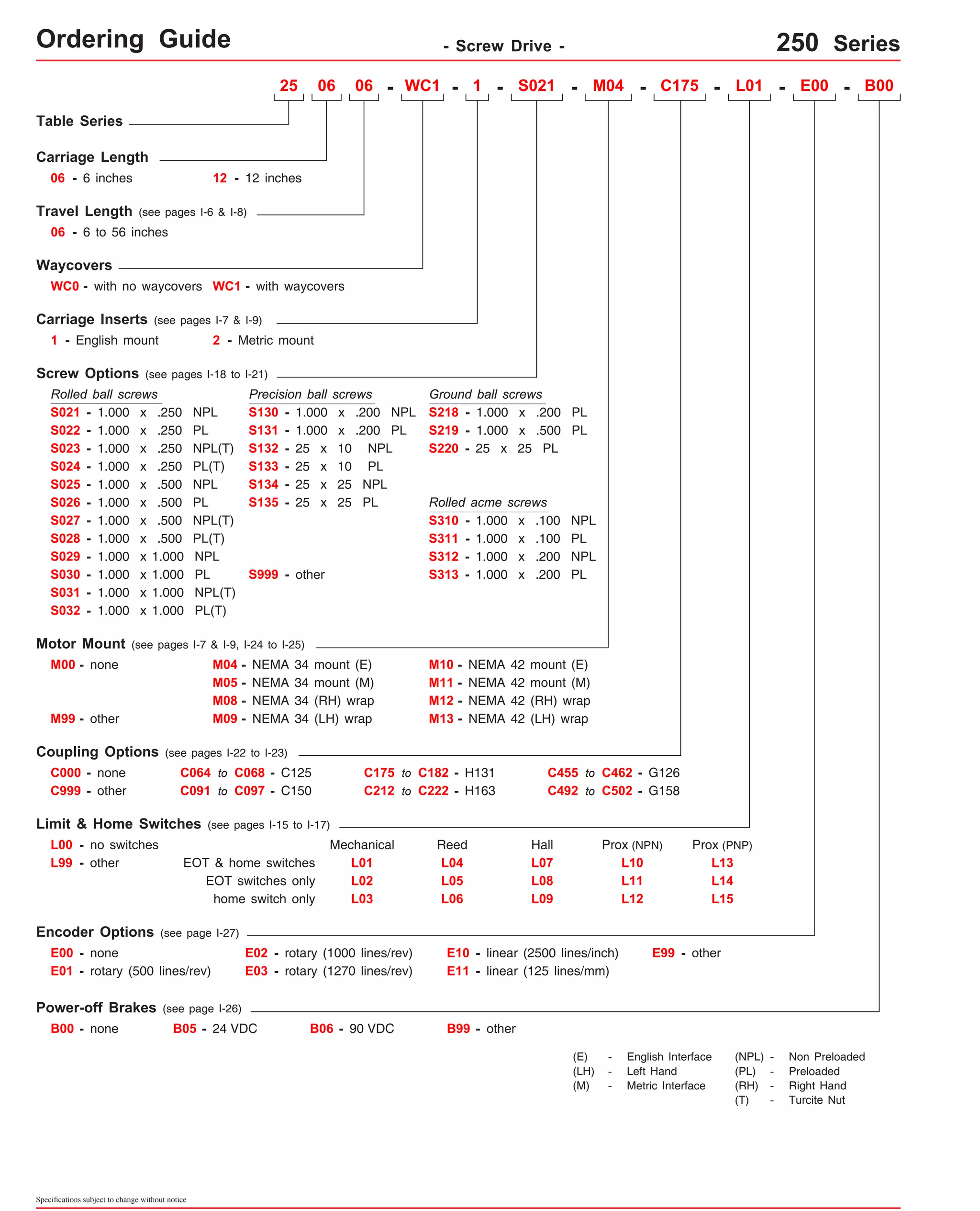
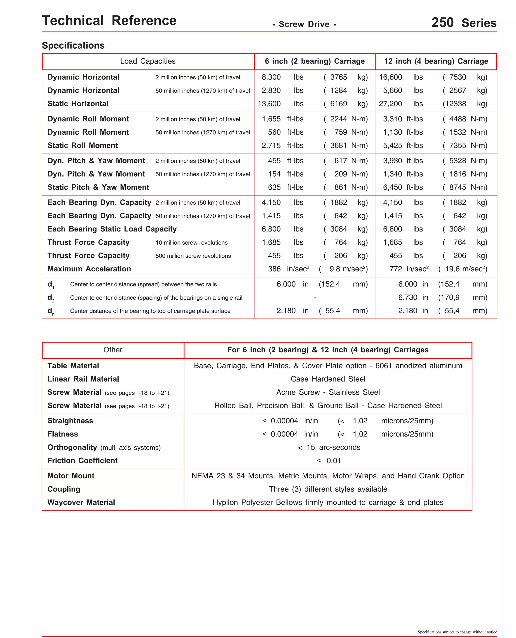
![Technical Reference - Screw Drive - 250-WC0 Series
Travel
Length
Table Dimensions
Model
Number lbs
inches
(mm)
2.370
(60,2) 21.5 7 16
(545)
2.310
(58,7) 28.5 9 20
(720)
2.310
(58,7) 35.5 11 24
(900)
2.310
(58,7) 42.5 13 28
(1075)
2.250
(57,1) 56.0 17 36
(1420)
1.870
(47,5) 7.5 5 12
(190)
1.810
(46,0) 14.5 7 16
(365)
1.870
(47,5) 21.5 9 20
(545)
1.810
(46,0) 28.5 11 24
(720)
1.810
(46,0) 13 28 35.5
(900)
42.5 15 32
(1075)
1.750
(44,4) 56.0 19 40
(1420)
Specifications subject to change without notice
(kg)
inches
(mm)
C
inches
(mm)
Mounting Dimensions
A
250607-WC0
15.25
51.8
(387,3)
(23,5) B
18.25
(463,5)
2.370
(60,2)
D M
8
Screw
Length
inches
(mm)
Table
Weight
3
17.05
(433)
23.92
(608)
31.05
(789)
37.92
(963)
44.92
(1141)
51.93
(1319)
65.80
(1671)
23.05
(585)
29.93
(760)
37.05
(941)
43.92
(1116)
50.92
(1293)
57.92
(1471)
71.80
(1824)
250614-WC0 22.12
25.12
2.310
5 12
65.6
(561,8)
(638,0)
(58,7) (29,8) 7.5
(190)
14.5
(365)
250621-WC0 29.25
32.25
80.4
(742,9)
(819,1)
(36,5) Dimensions & Specifications
250628-WC0 36.12
39.12
95.2
(917,4)
(993,6)
(43,2) 250635-WC0 43.12
46.12
110.0
(1095,2)
(1171,4)
(49,9) 250642-WC0 50.12
53.12
124.8
(1273,0)
(1349,2)
(56,7) 250656-WC0 64.00
67.00
153.4
(1625,6)
(1701,8)
(69,6) 251207-WC0 21.25
24.25
76.8
(539,7)
(615,9)
(34,8) 251214-WC0 28.12
31.12
91.6
(714,2)
(790,4)
(41,5) 251221-WC0 35.25
38.25
106.4
(895,3)
(971,5)
(48,3) 251228-WC0 42.12
45.12
121.2
(1069,8)
(1146,0)
(55,0) 136.0
52.12
(1323,8)
251235-WC0 (61,7) 49.12
(1247,6)
251242-WC0 56.12
59.12
1.810
149.8
(1425,4)
(1501,6)
(46,0)
(67,9) 251256-WC0 70.00
73.00
179.4
(1778,0)
(1854,2)
(81,4) - Without Waycovers -
06 = 6 inch (152,4 mm) carriage length; 2 bearings; carriage weight = 14.0 lbs. (6,35 kg)
12 = 12 inch (304,8 mm) carriage length; 4 bearings; carriage weight = 26.0 lbs. (11,79 kg)
Footnotes:
(1)
(1)
Weight shown is with a 1.000 inch (25 mm) diameter screw, a NEMA 34 motor mount [0.54 lbs (0,24 kg)], and a C125 style [0.22 lbs (0,10 kg)] coupling.
version: 01/2014](https://image.slidesharecdn.com/lintechpositioningsystemscatalog-141018113223-conversion-gate01/75/Lintech-positioning-systems_catalog-319-2048.jpg)
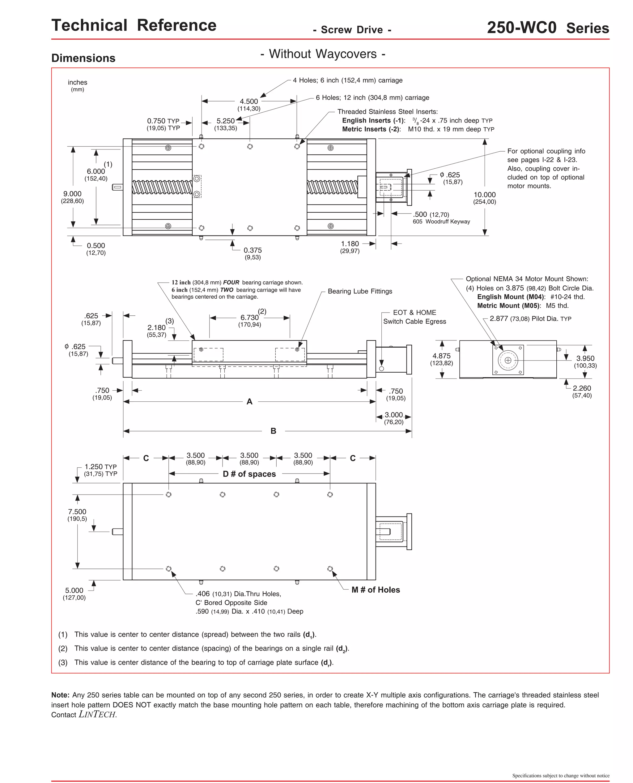
![Technical Reference - Screw Drive - 250-WC1 Series
Travel
Length
Table Dimensions
Model
Number lbs
inches
(mm)
2.370
(60,2) 16 31.05
(789) 18 7
(455)
2.310
(58,7) 20 37.92
(963) 24 9
(605)
2.310
(58,7) 24 44.92
(1141) 30 11
(760)
2.310
(58,7) 28 51.93
(1319) 36 13
(910)
2.250
(57,1) 36 65.80
(1671) 48 17
(1215)
1.870
(47,5) 12 23.05
(585) 6 5
(150)
1.810
(46,0) 16 29.93
(760) 12 7
(300)
1.870
(47,5) 20 37.05
(941) 18 9
(455)
1.810
(46,0) 24 43.92
(1116) 24 11
(605)
1.750
(44,4) 40 71.80
(1824) 48 19
(1215)
Specifications subject to change without notice
(kg)
inches
(mm)
C
inches
(mm)
Mounting Dimensions
A
250606-WC1
15.25
54.0
(387,3)
(24,5) B
18.25
(463,5)
2.370
(60,2)
D M
8
Screw
Length
inches
(mm)
17.05
(433)
(1)
Table
Weight
3
250612-WC1 22.12
25.12
2.310
5
12 23.92
69.0
(561,8)
(638,0)
(58,7) (608) (31,3) 6
(150)
12
(300)
250618-WC1 29.25
32.25
85.0
(742,9)
(819,1)
(38,6) Dimensions & Specifications
250624-WC1 36.12
39.12
101.0
(917,4)
(993,6)
(45,8) 250630-WC1 43.12
46.12
117.0
(1095,2)
(1171,4)
(53,1) 250636-WC1 50.12
53.12
133.0
(1273,0)
(1349,2)
(60,3) 250648-WC1 64.00
67.00
164.0
(1625,6)
(1701,8)
(74,4) 251206-WC1 21.25
24.25
79.0
(539,7)
(615,9)
(35,8) 251212-WC1 28.12
31.12
95.0
(714,2)
(790,4)
(43,1) 251218-WC1 35.25
38.25
111.0
(895,3)
(971,5)
(50,3) 251224-WC1 42.12
45.12
127.0
(1069,8)
(1146,0)
(57,6) 143.0
52.12
(1323,8)
1.810
(46,0) 28 50.92
251230-WC1 30
49.12
(760)
(1247,6)
13 (1293) (64,9) 251236-WC1 36 56.12
59.12
1.810
15
32 57.92
158.0
(910)
(1425,4)
(1501,6)
(46,0)
(1471)
(71,7) 251248-WC1 70.00
73.00
190.0
(1778,0)
(1854,2)
(86,2) - With Waycovers -
06 = 6 inch (152,4 mm) carriage length; 2 bearings; carriage weight = 14.0 lbs. (6,35 kg)
12 = 12 inch (304,8 mm) carriage length; 4 bearings; carriage weight = 26.0 lbs. (11,79 kg)
Footnotes:
(1) Weight shown is with a 1.000 inch (25 mm) diameter screw, a NEMA 34 motor mount [0.54 lbs (0,24 kg)], and a C125 style [0.22 lbs (0,10 kg)] coupling.](https://image.slidesharecdn.com/lintechpositioningsystemscatalog-141018113223-conversion-gate01/75/Lintech-positioning-systems_catalog-321-2048.jpg)

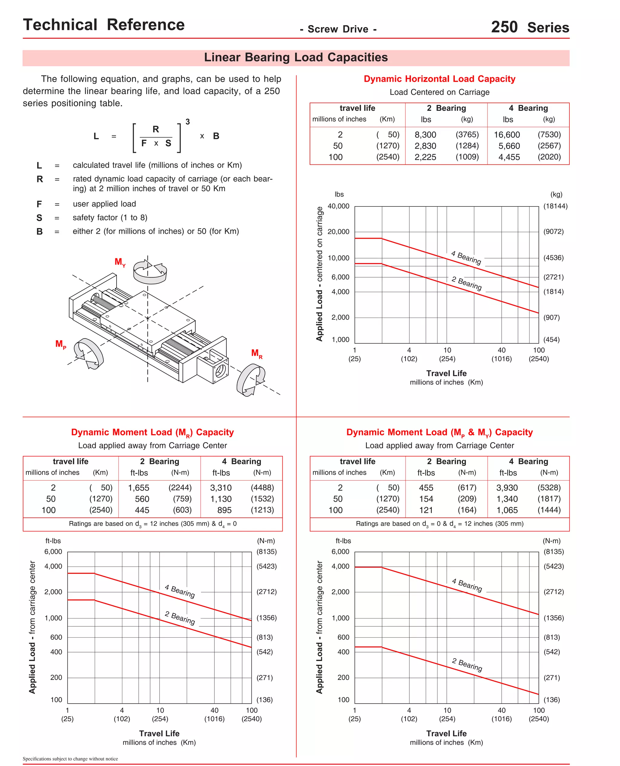
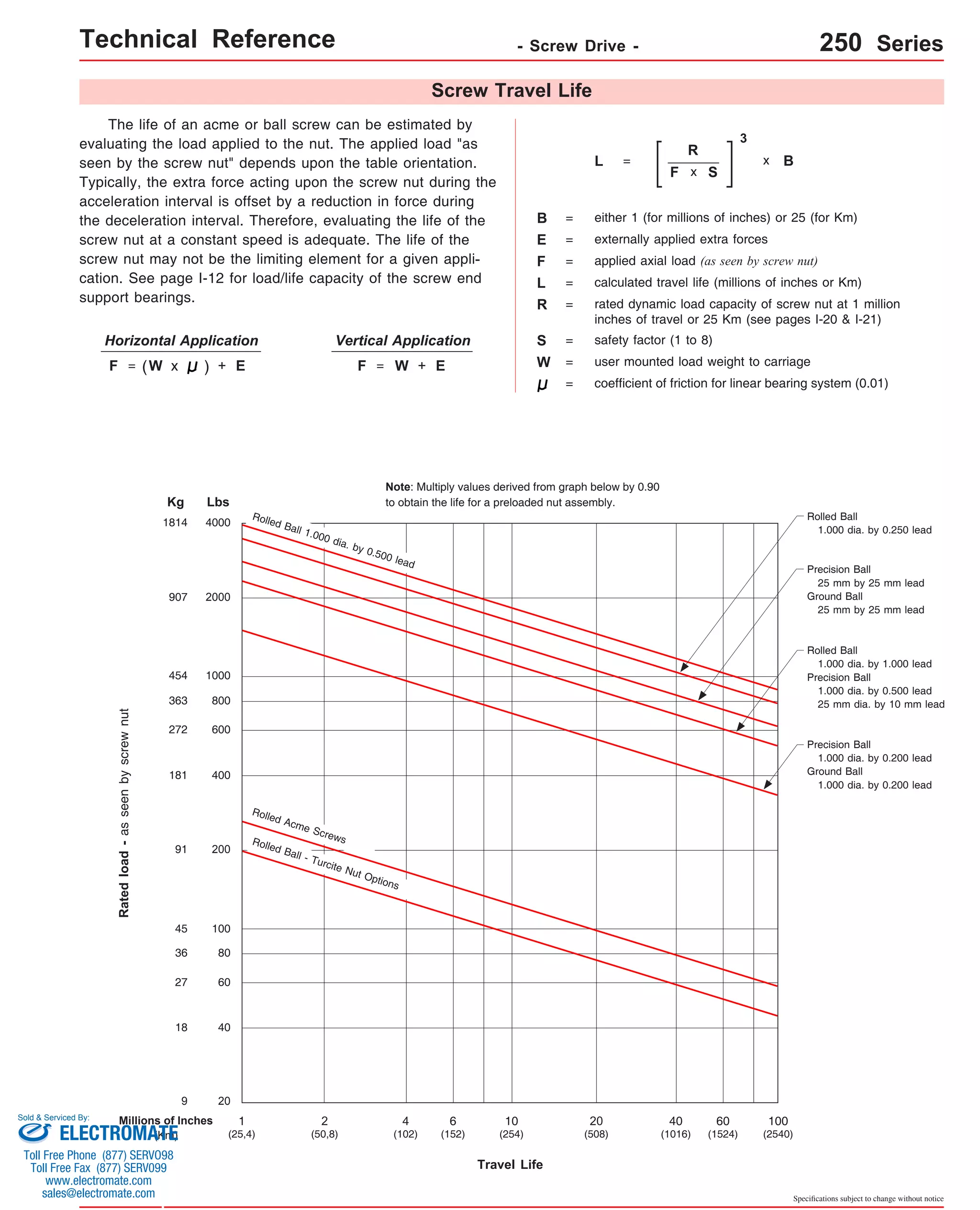
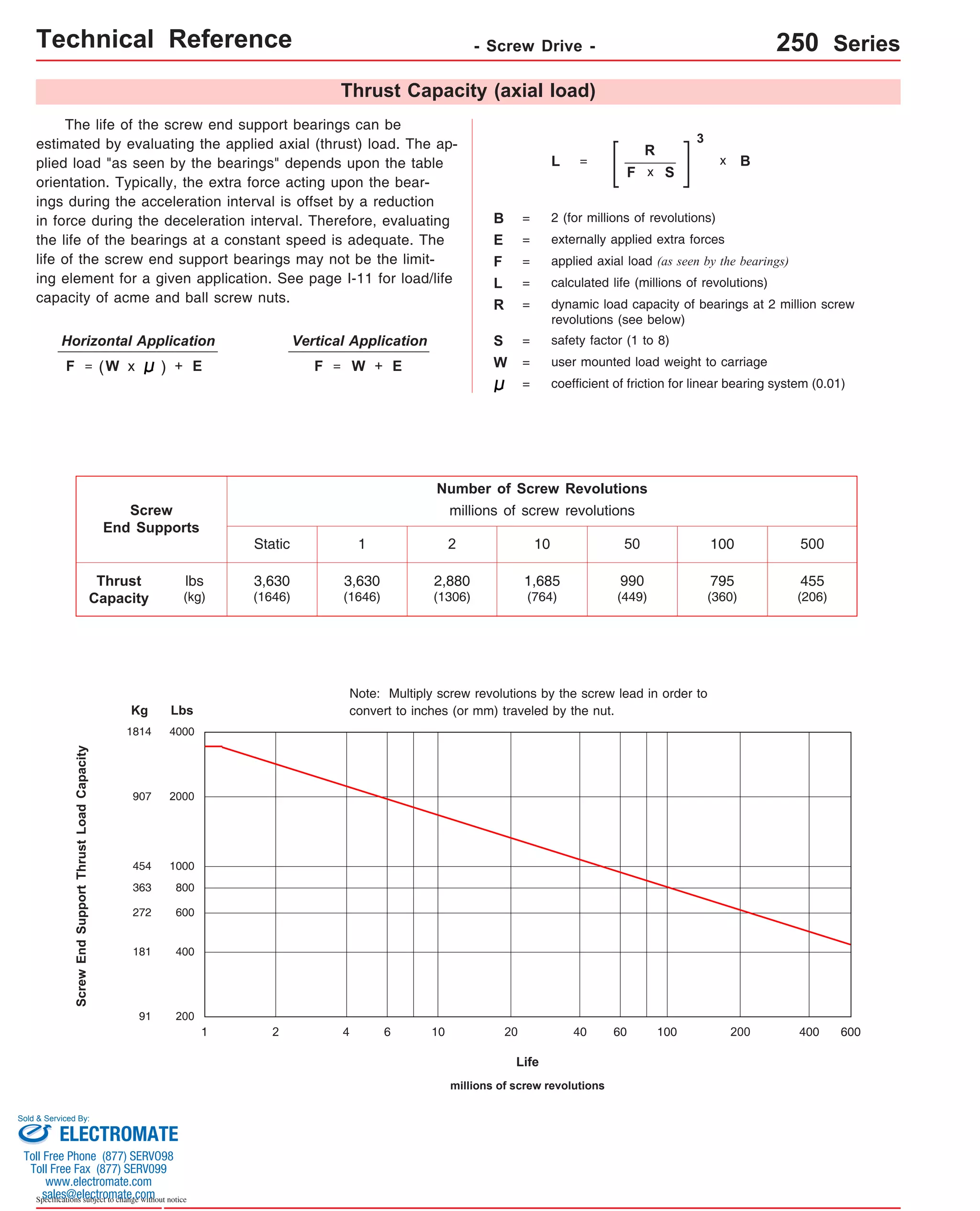
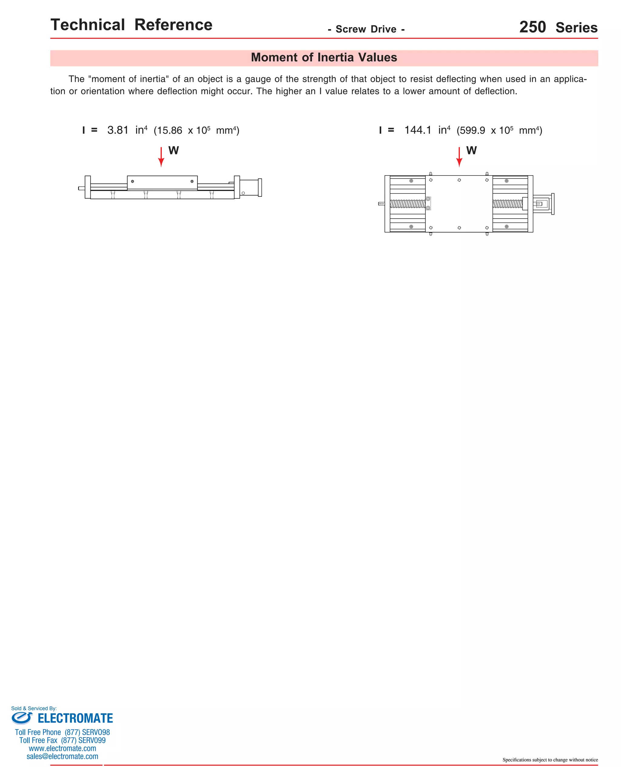
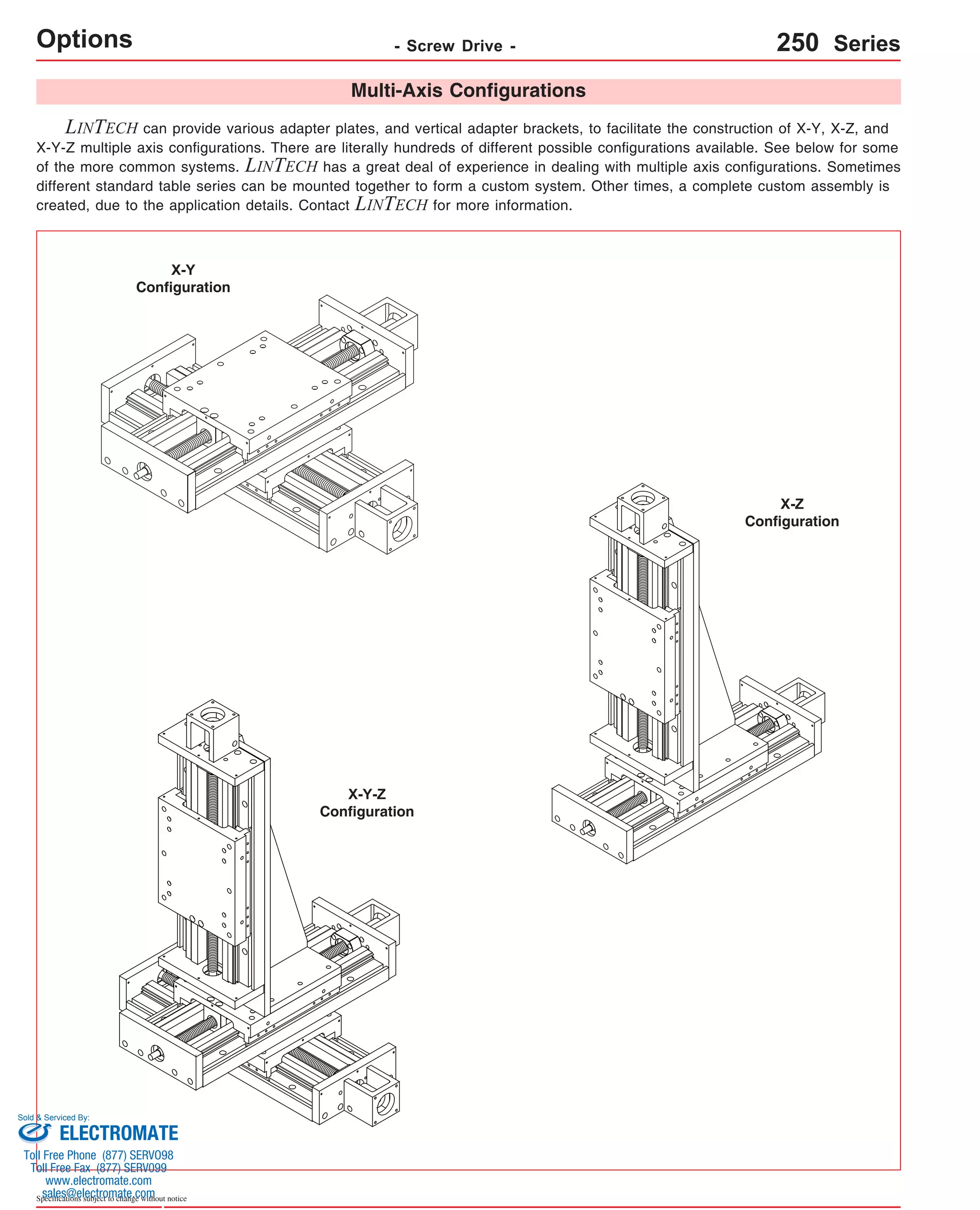
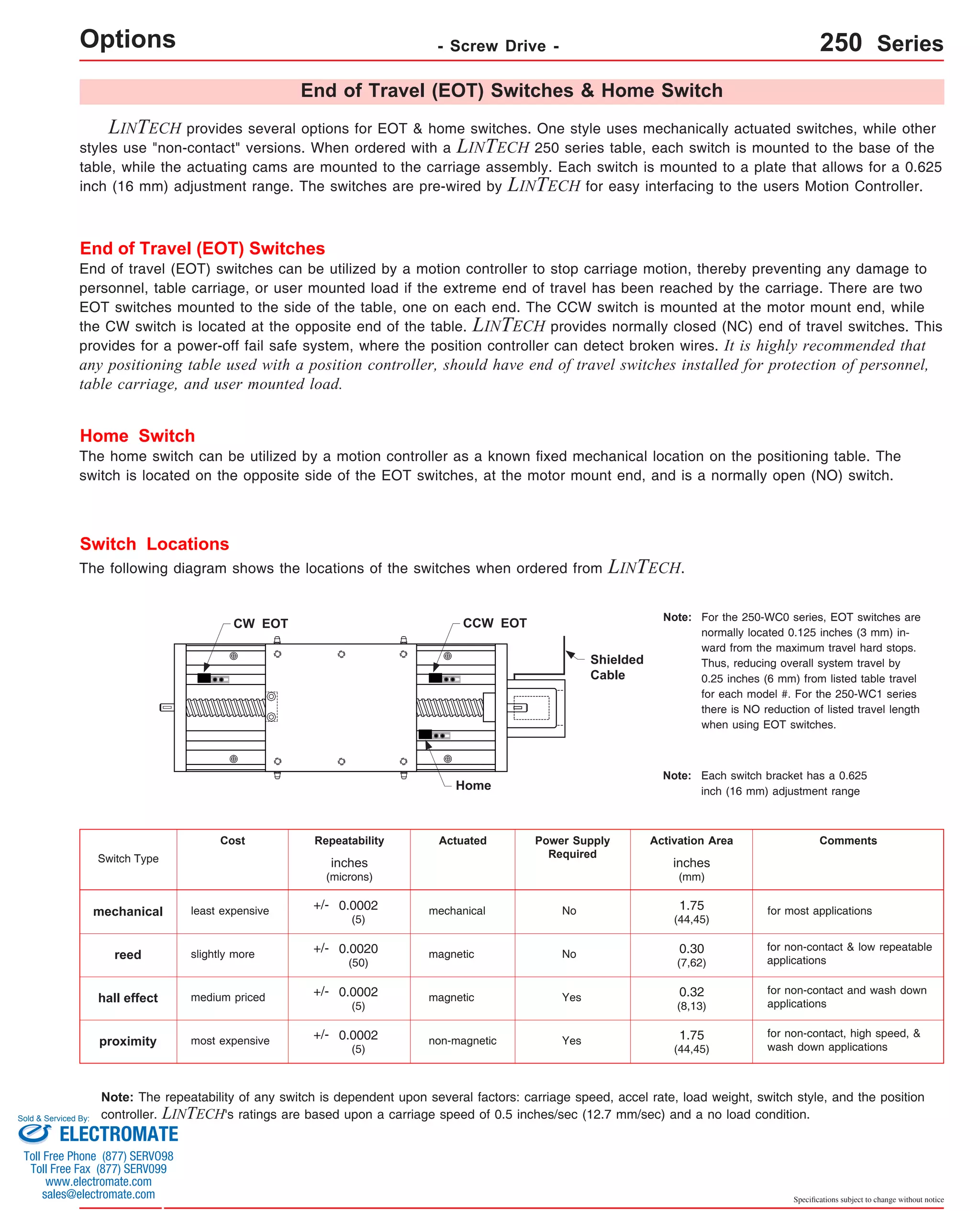

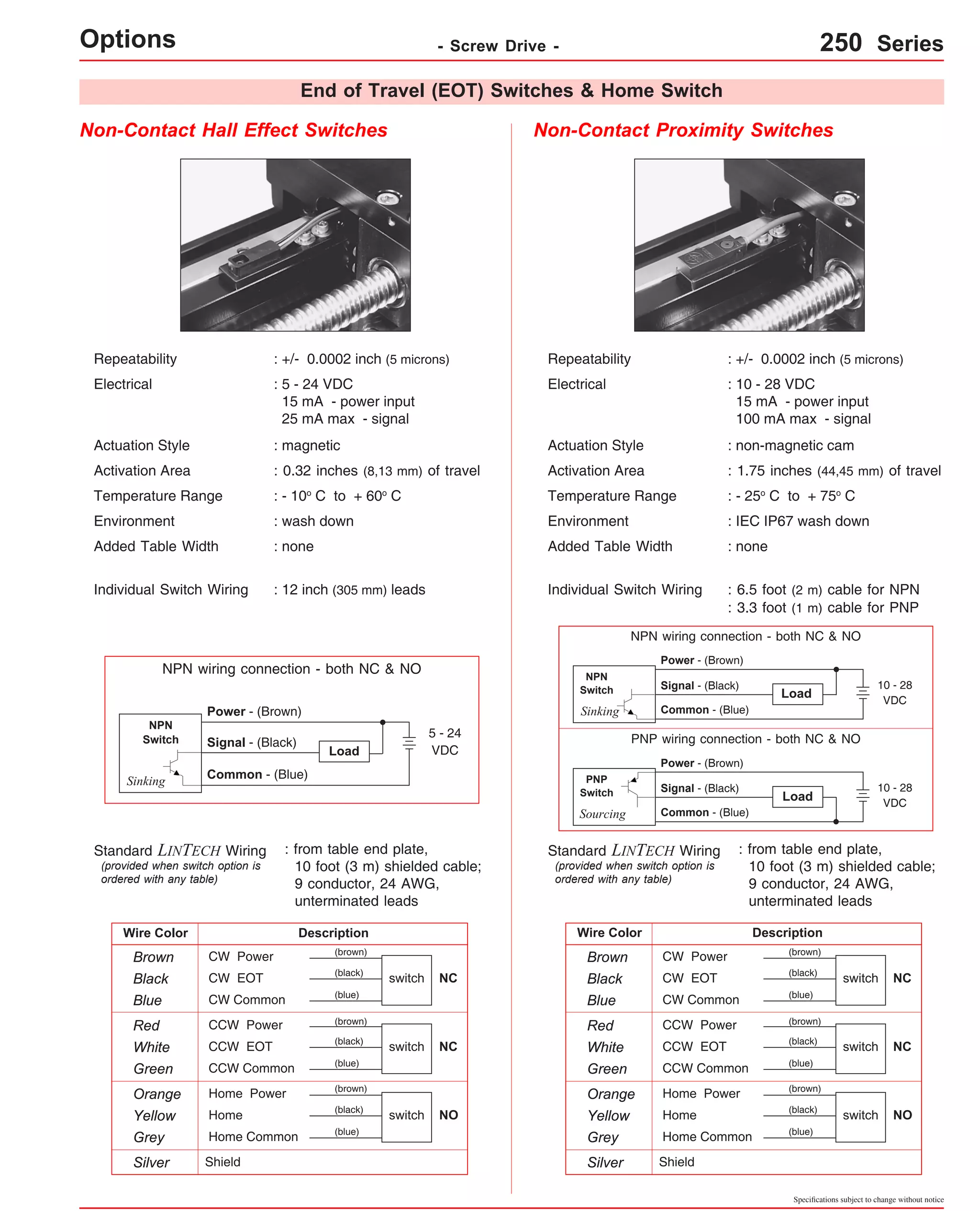
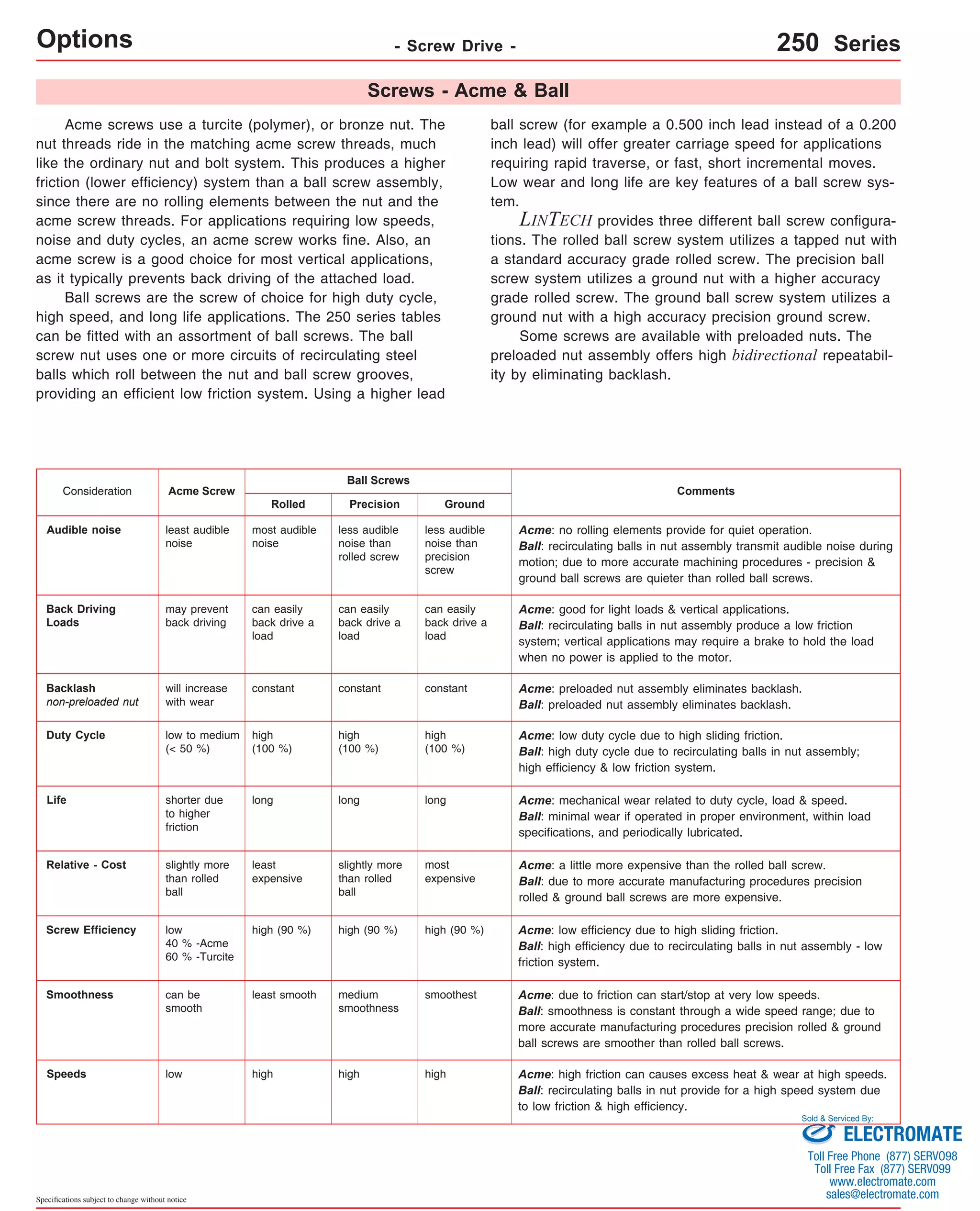
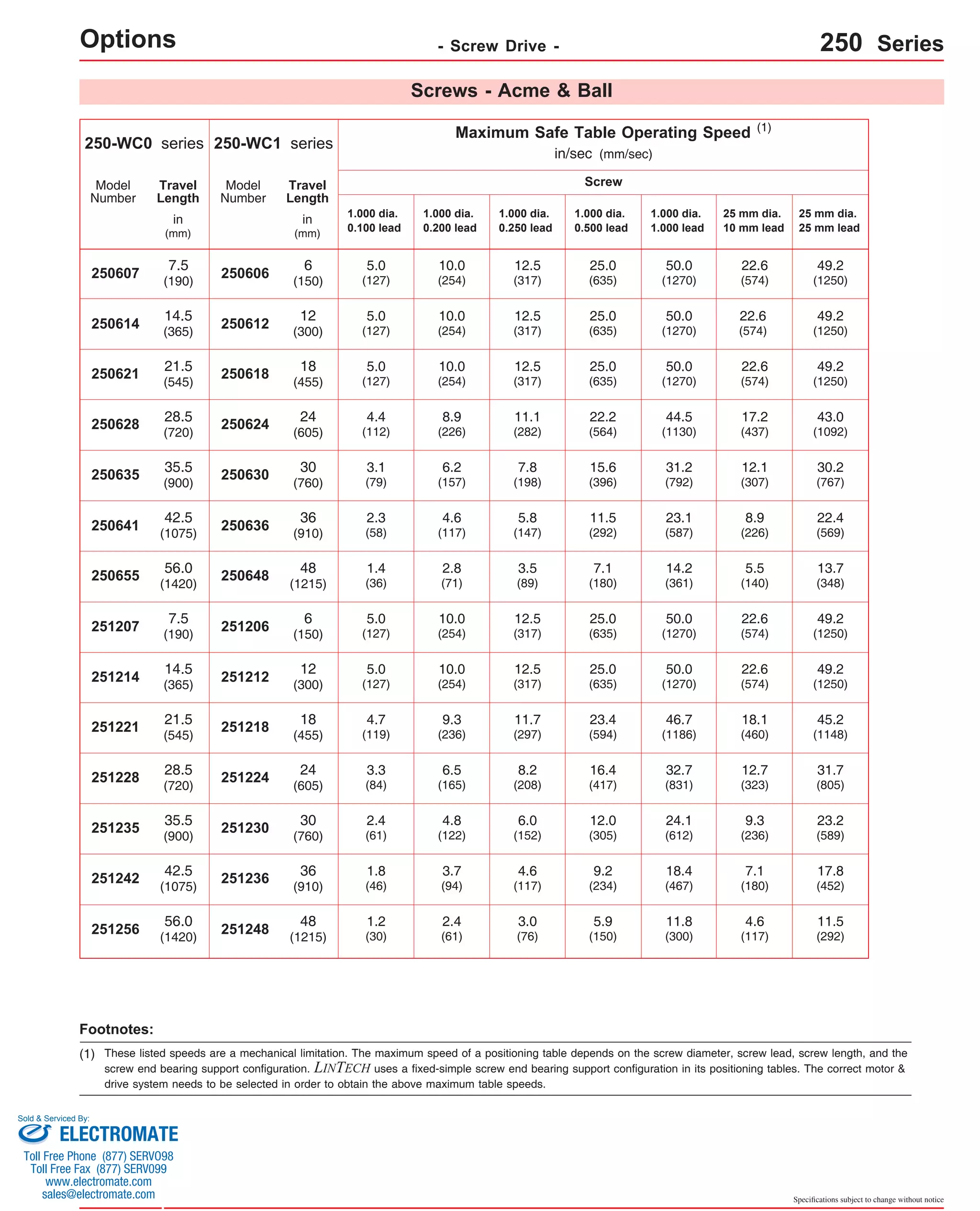

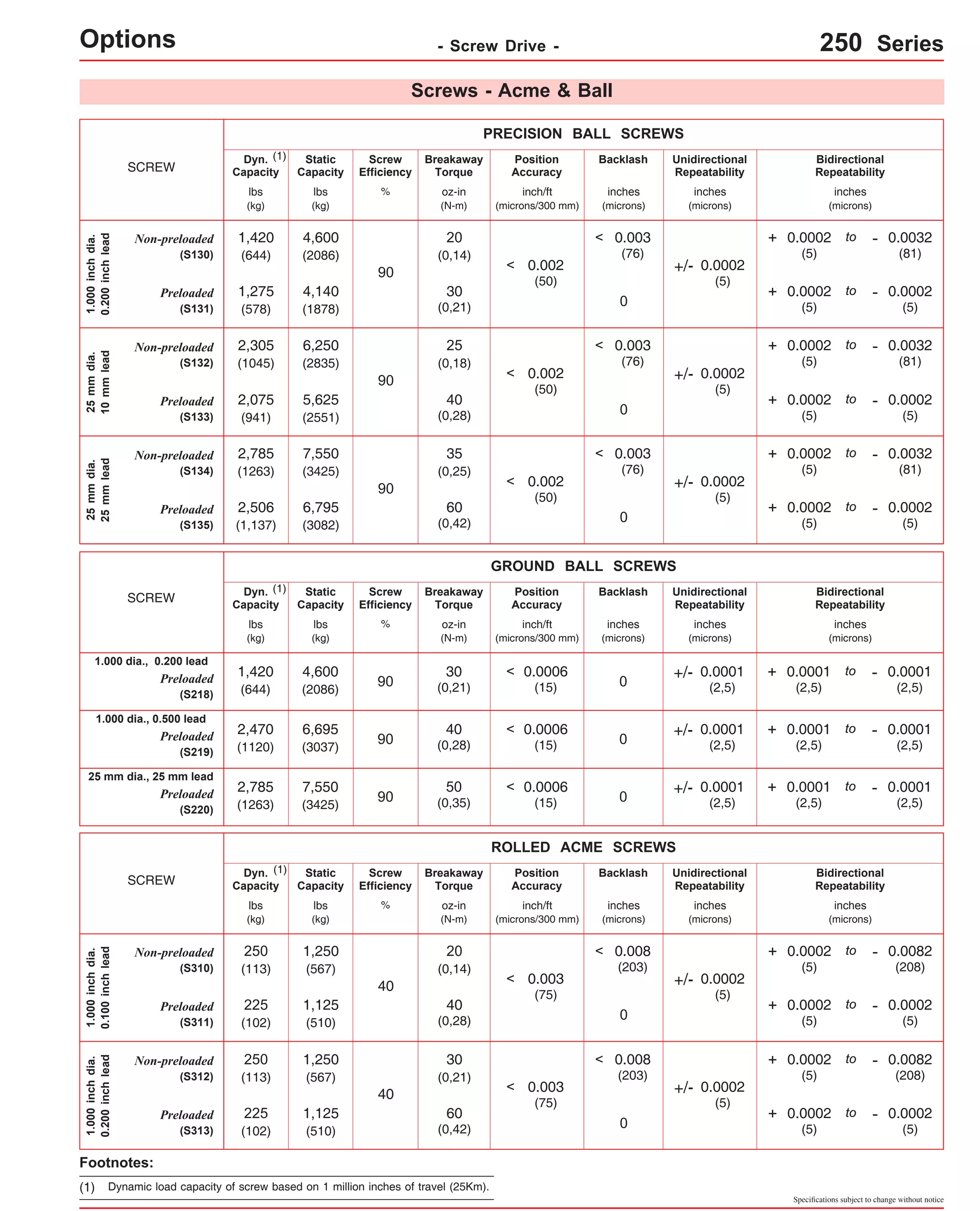
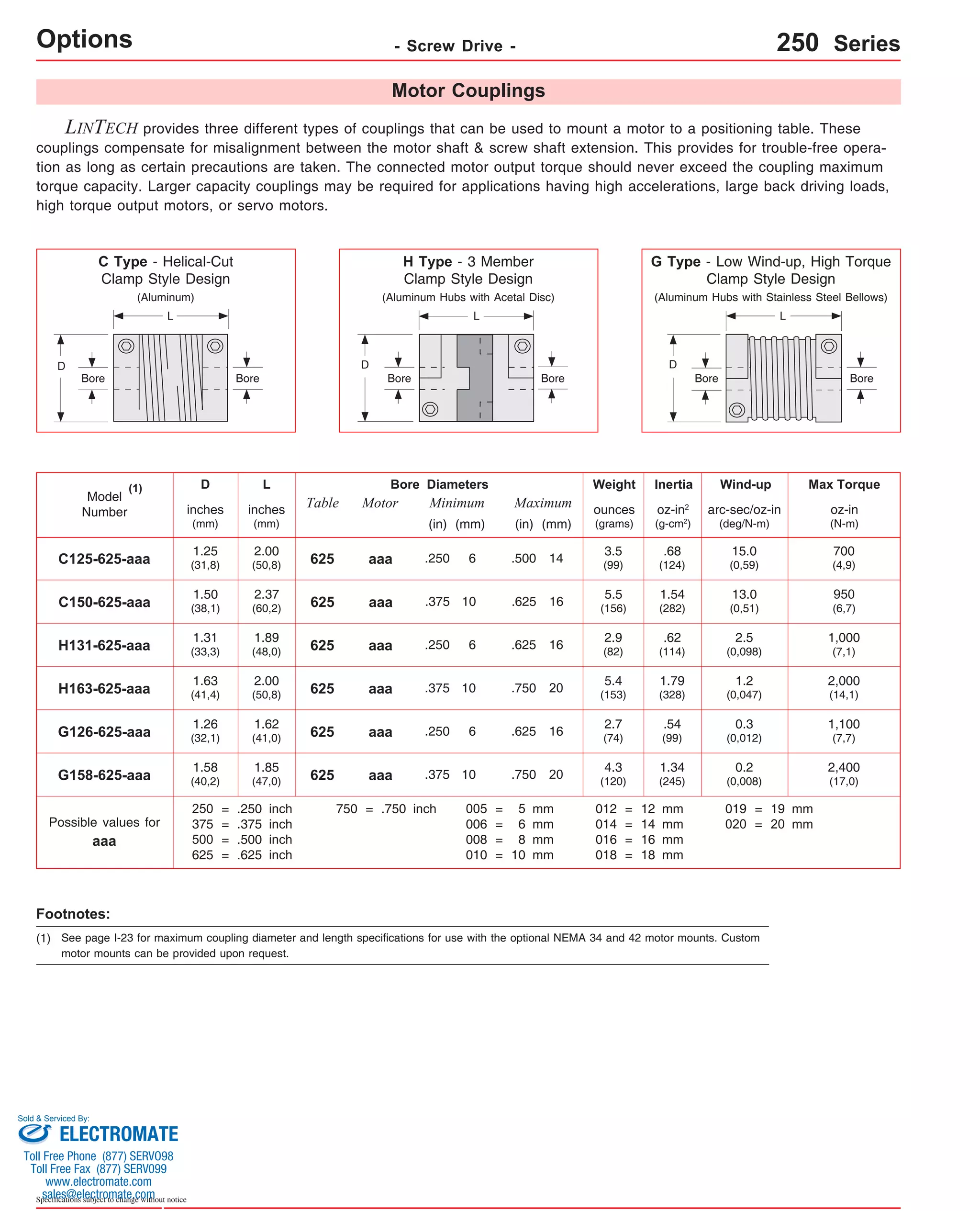
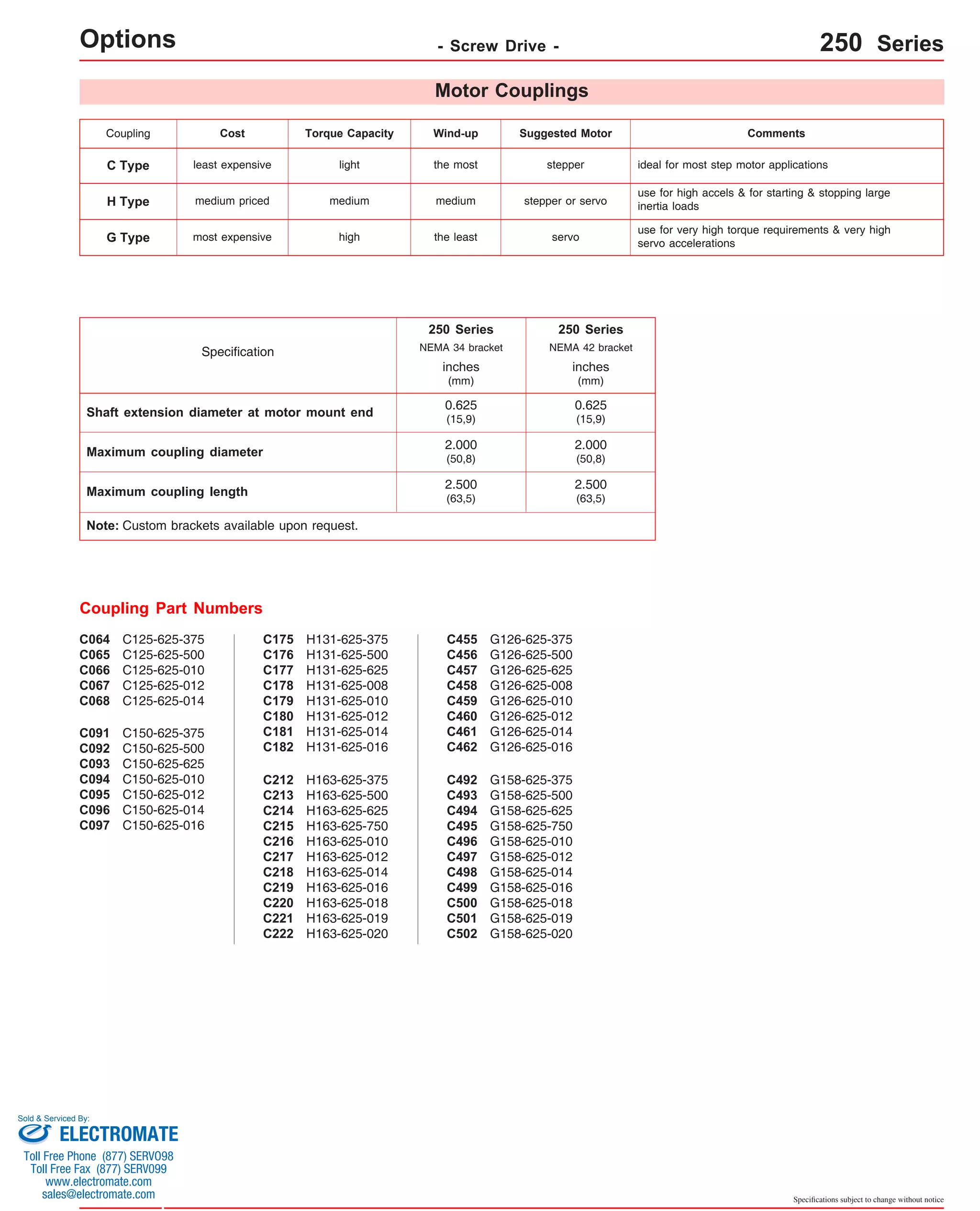
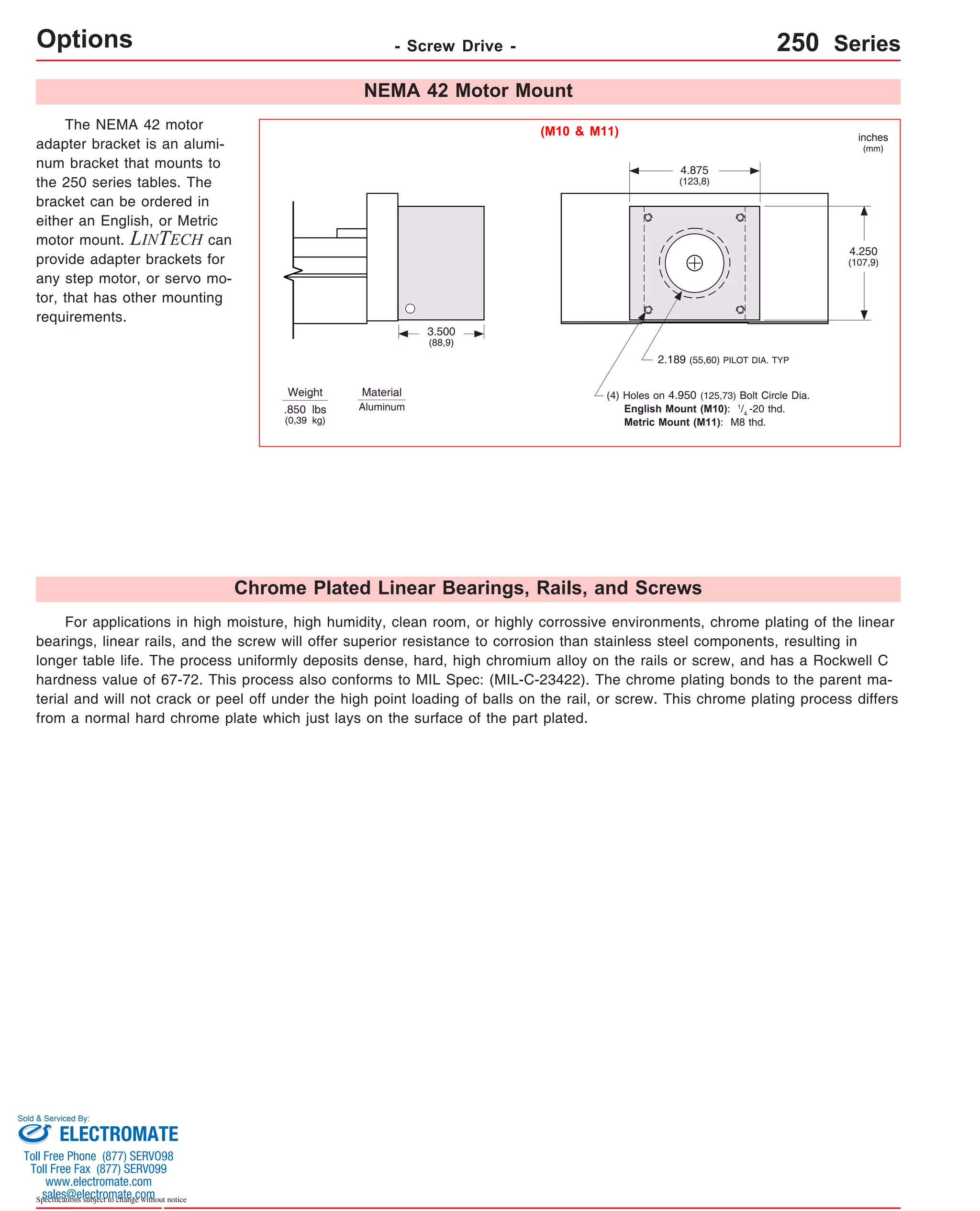
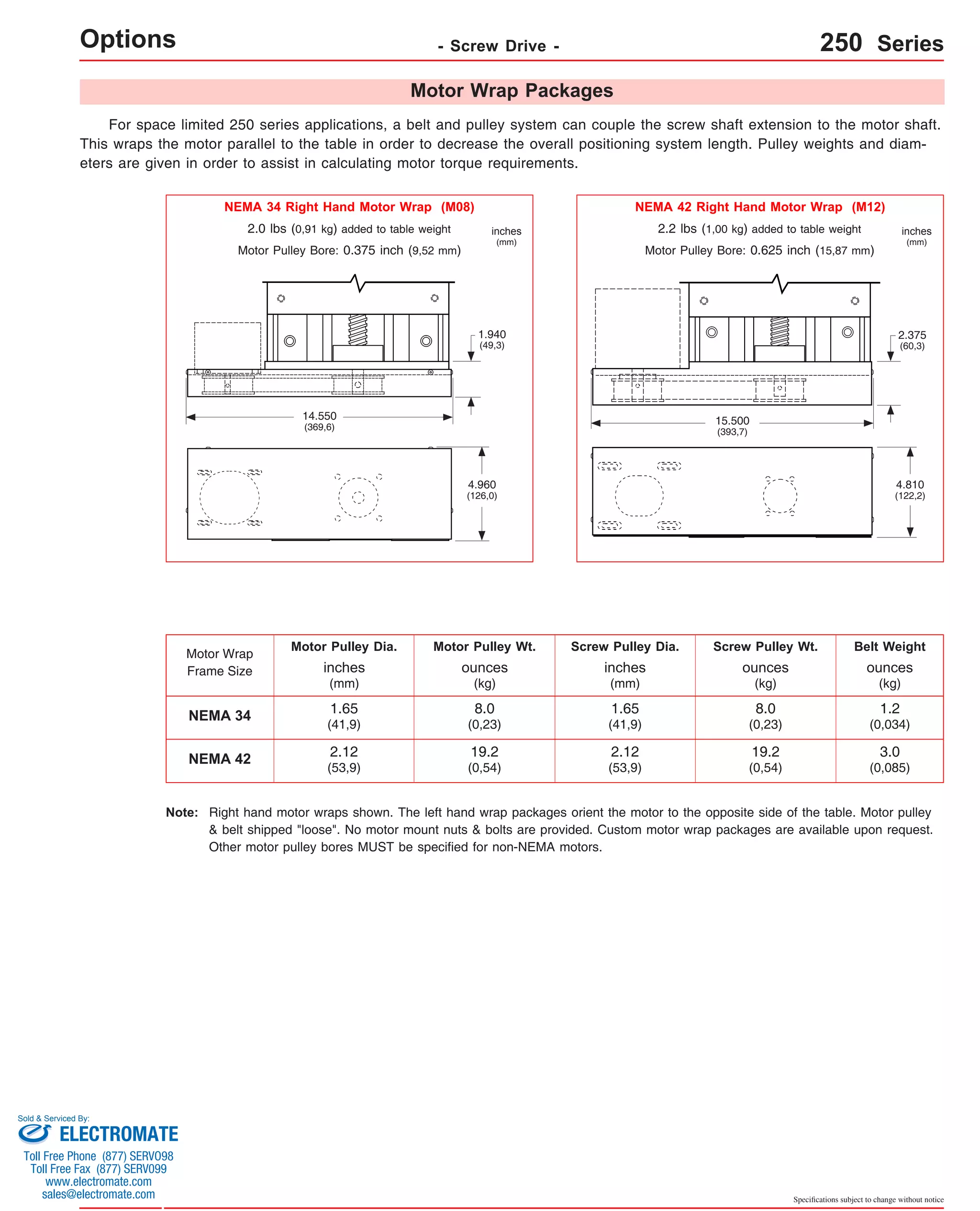

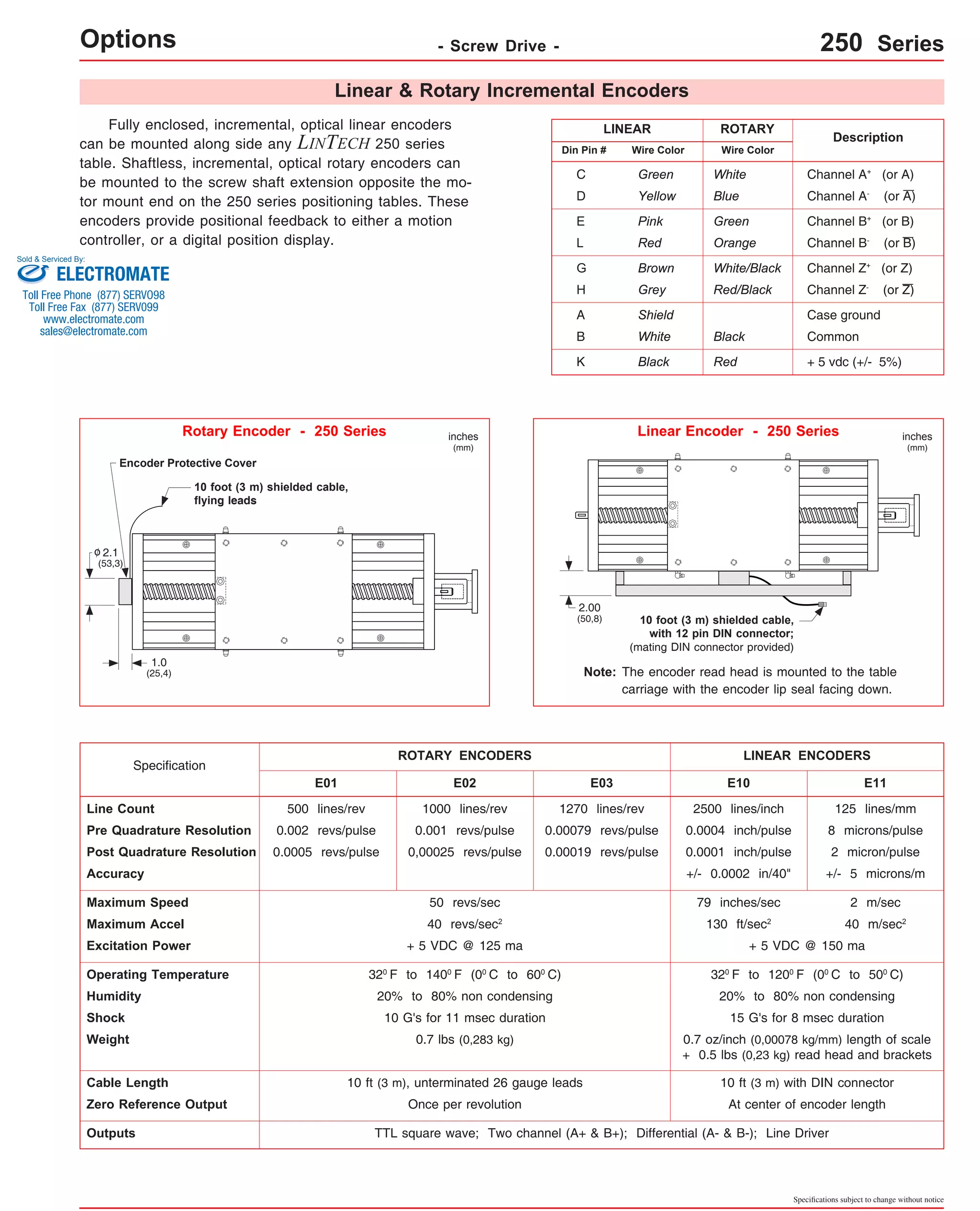
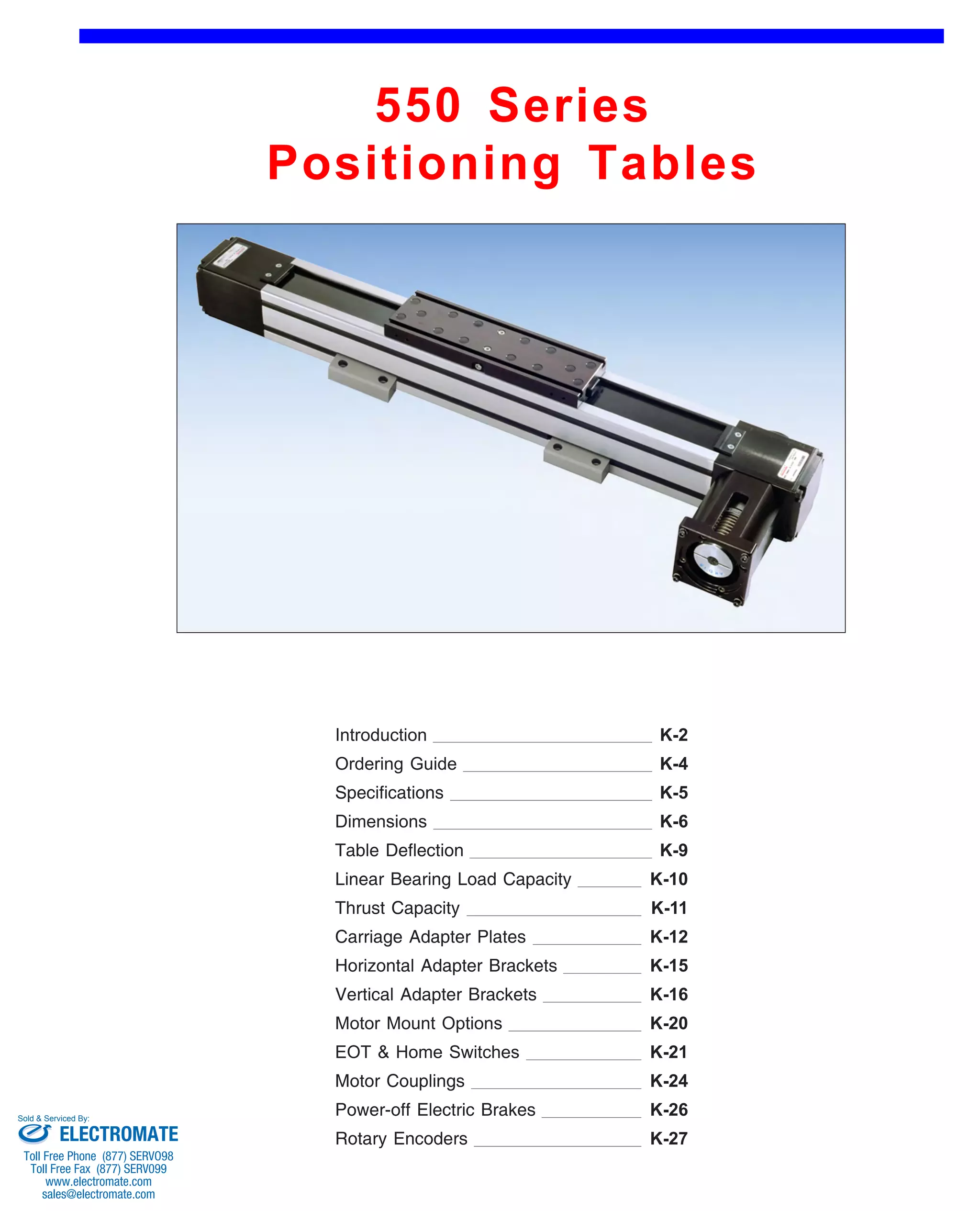
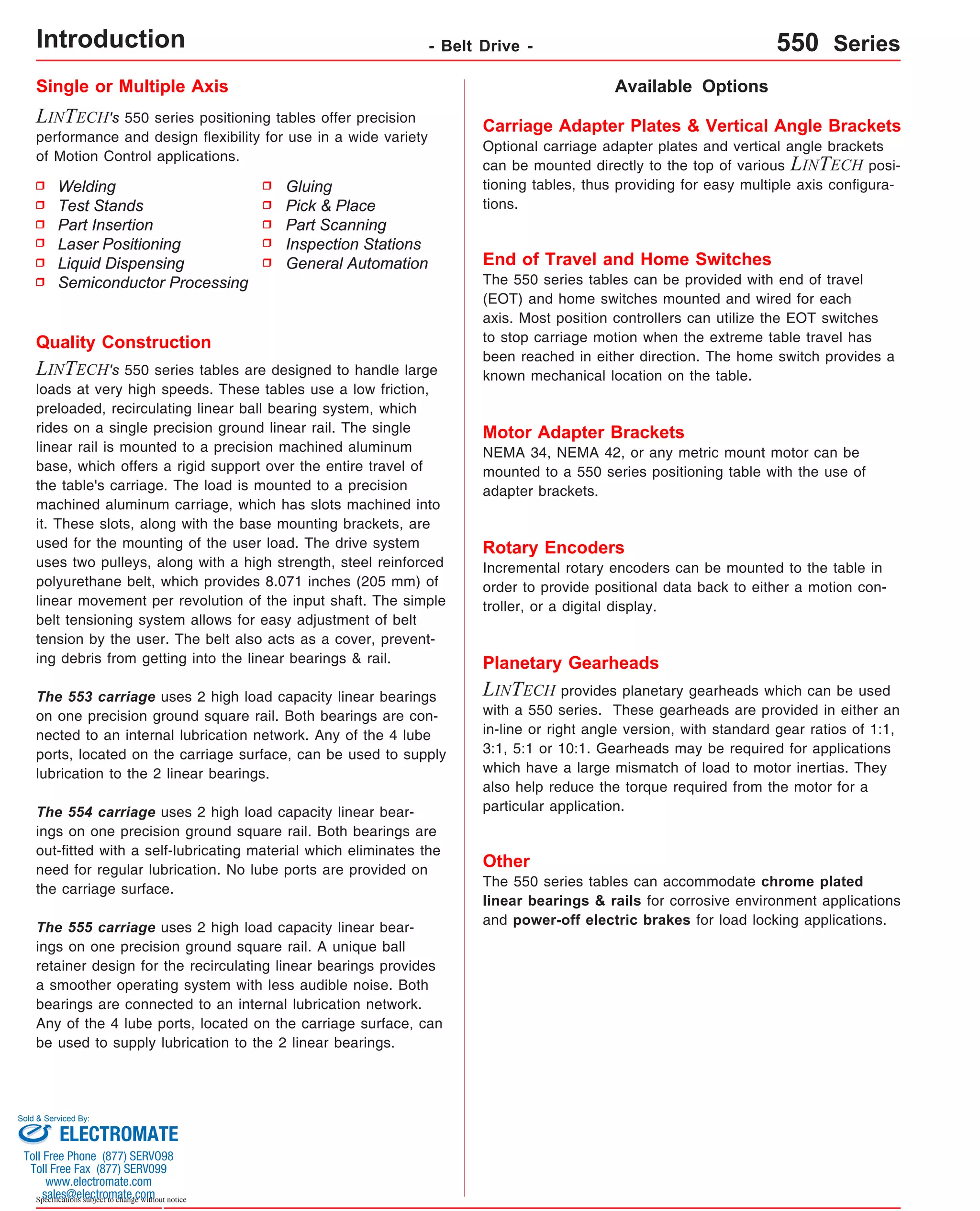
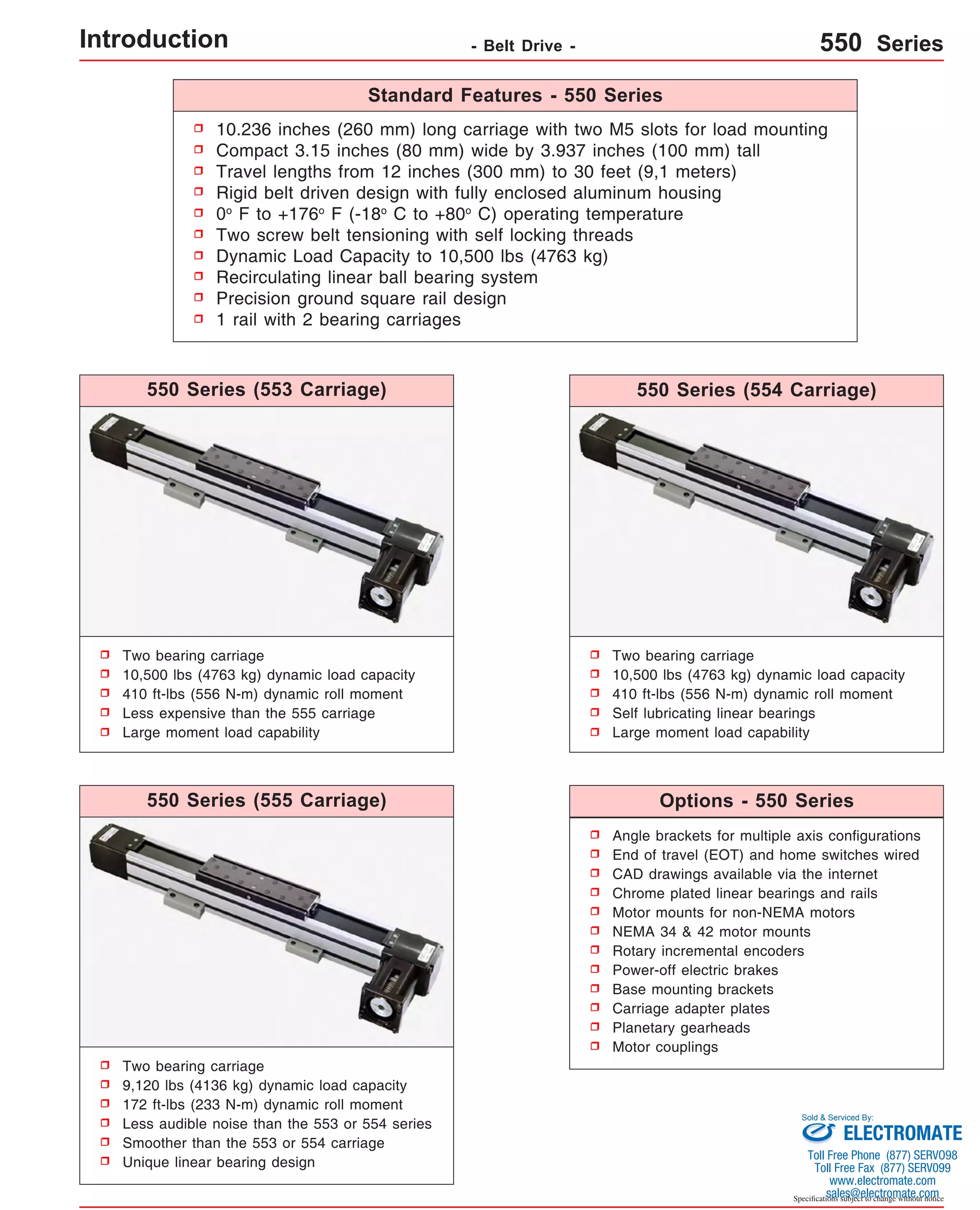
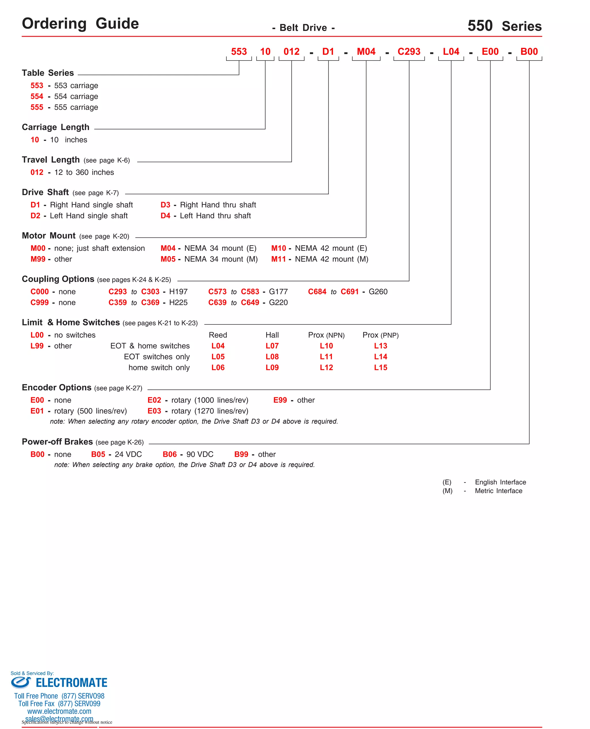
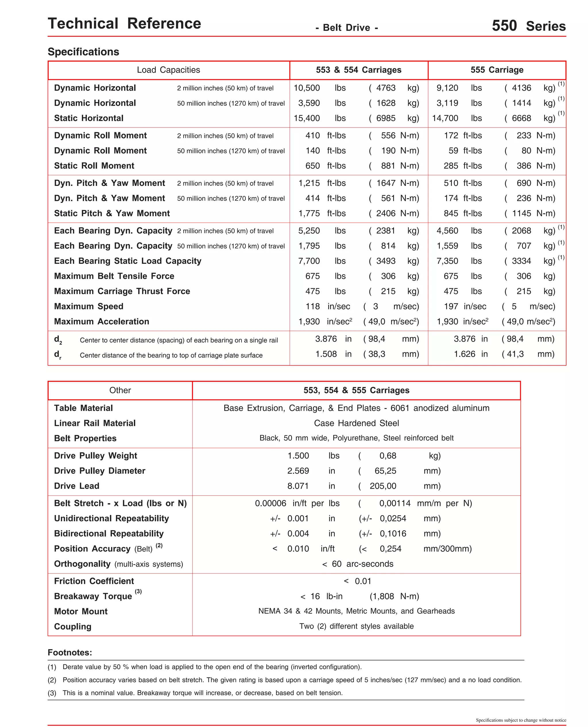
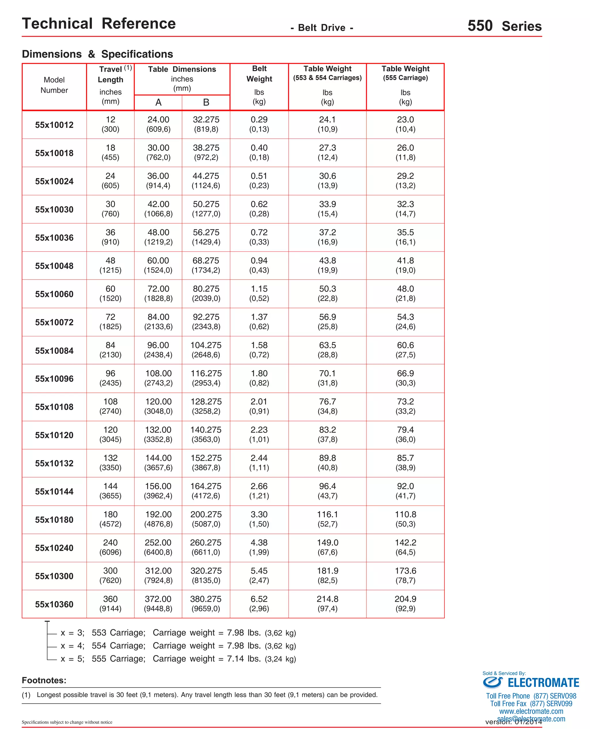
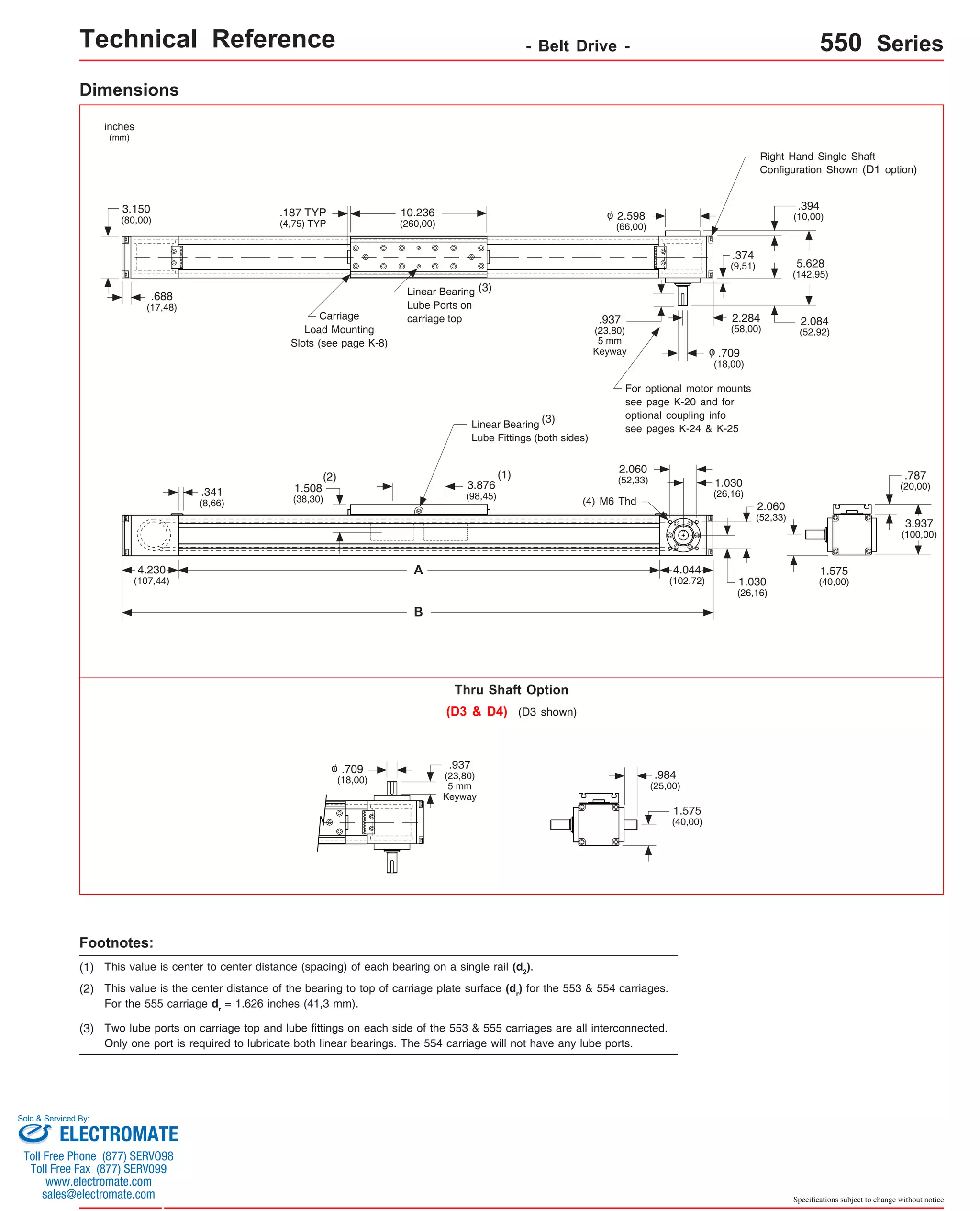
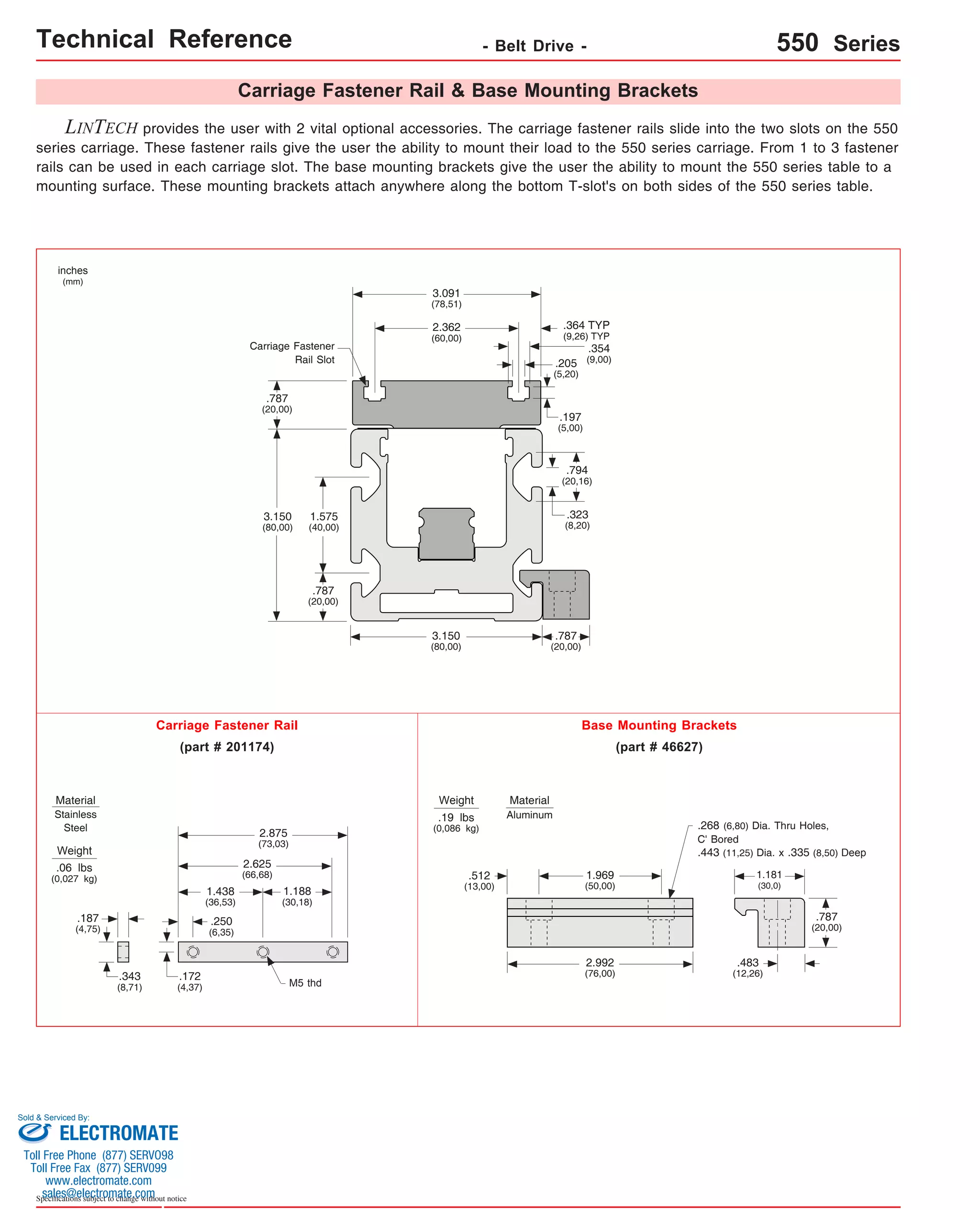
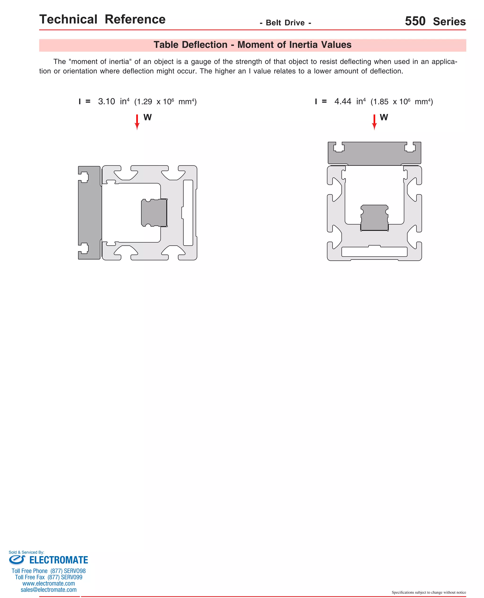
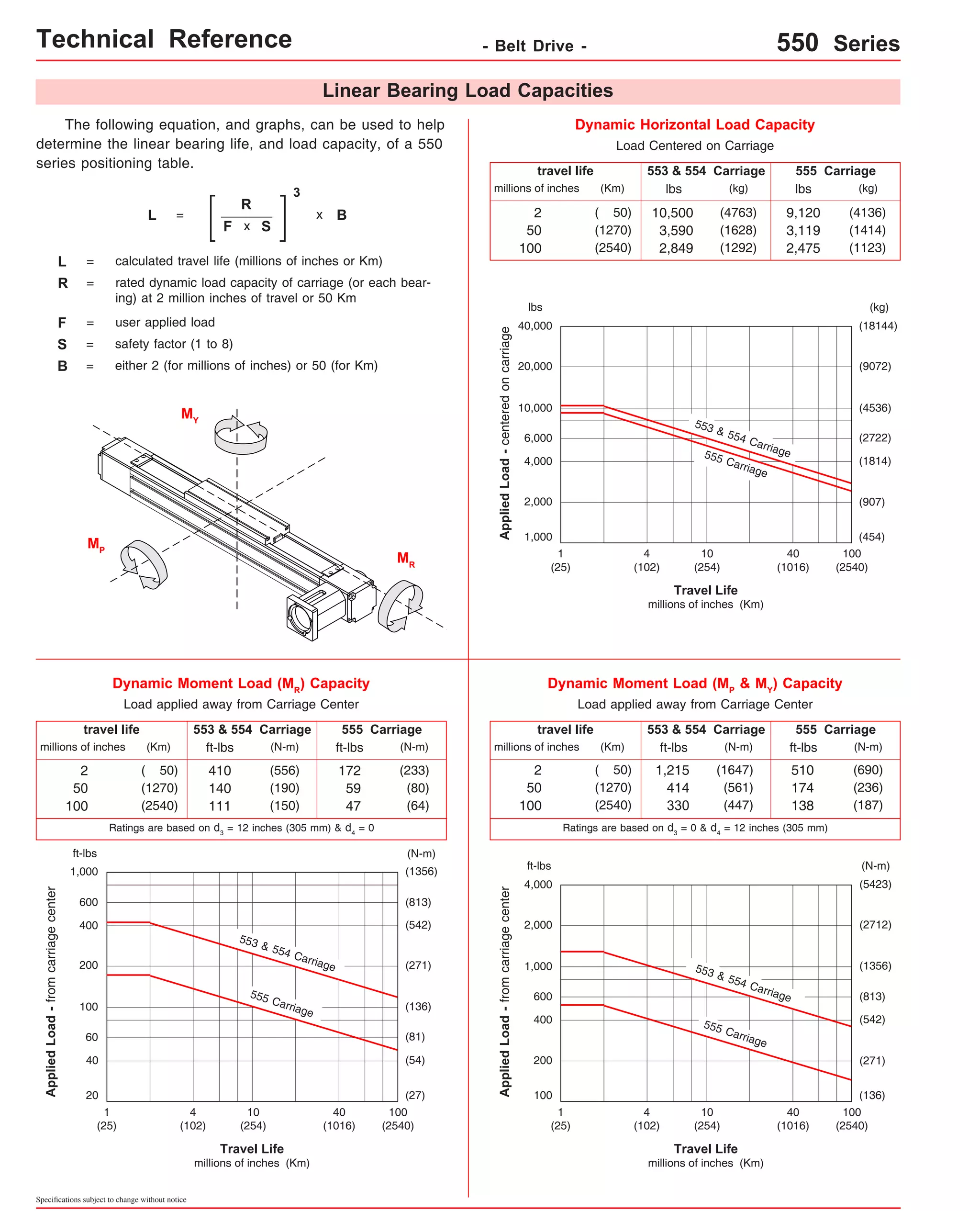
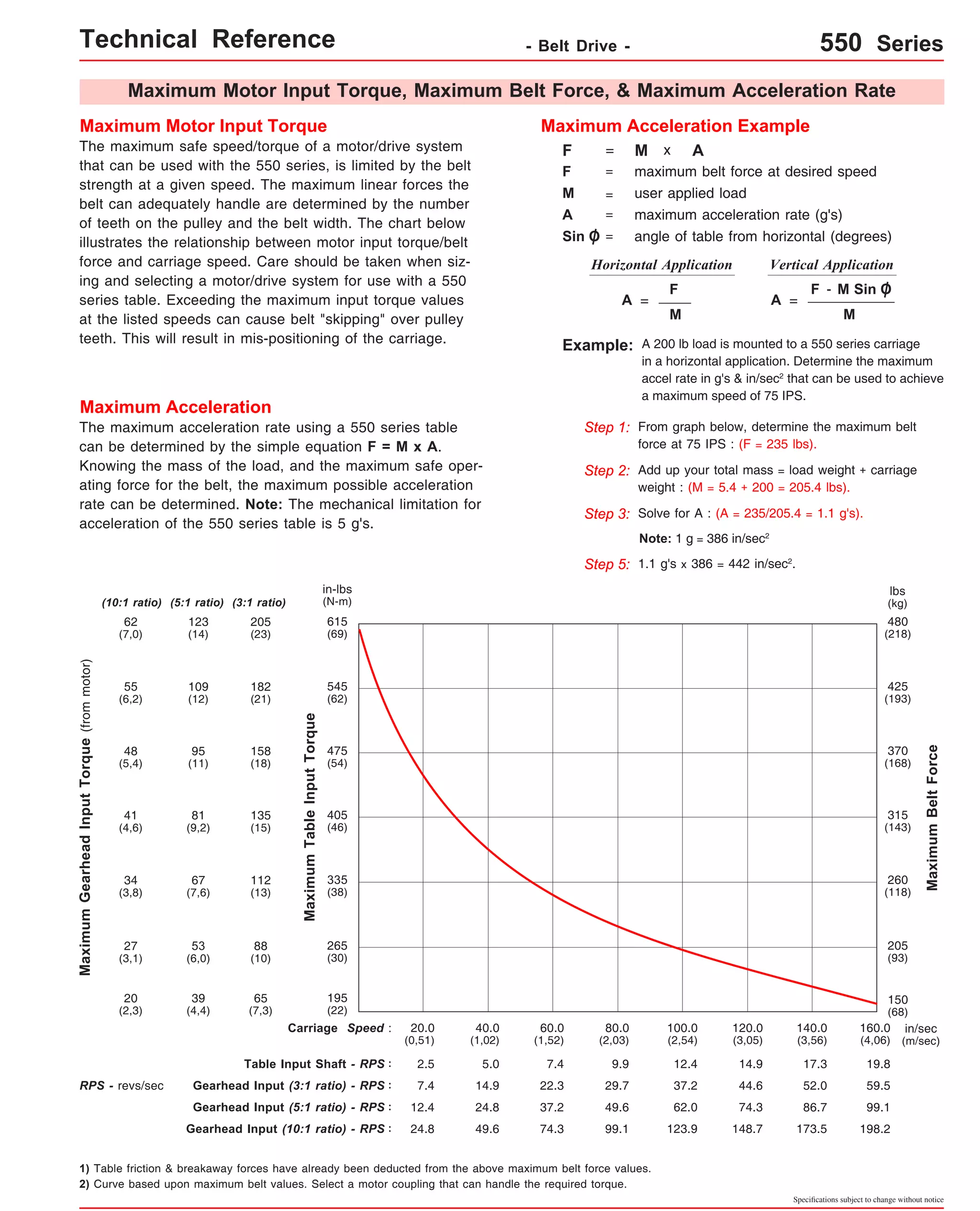
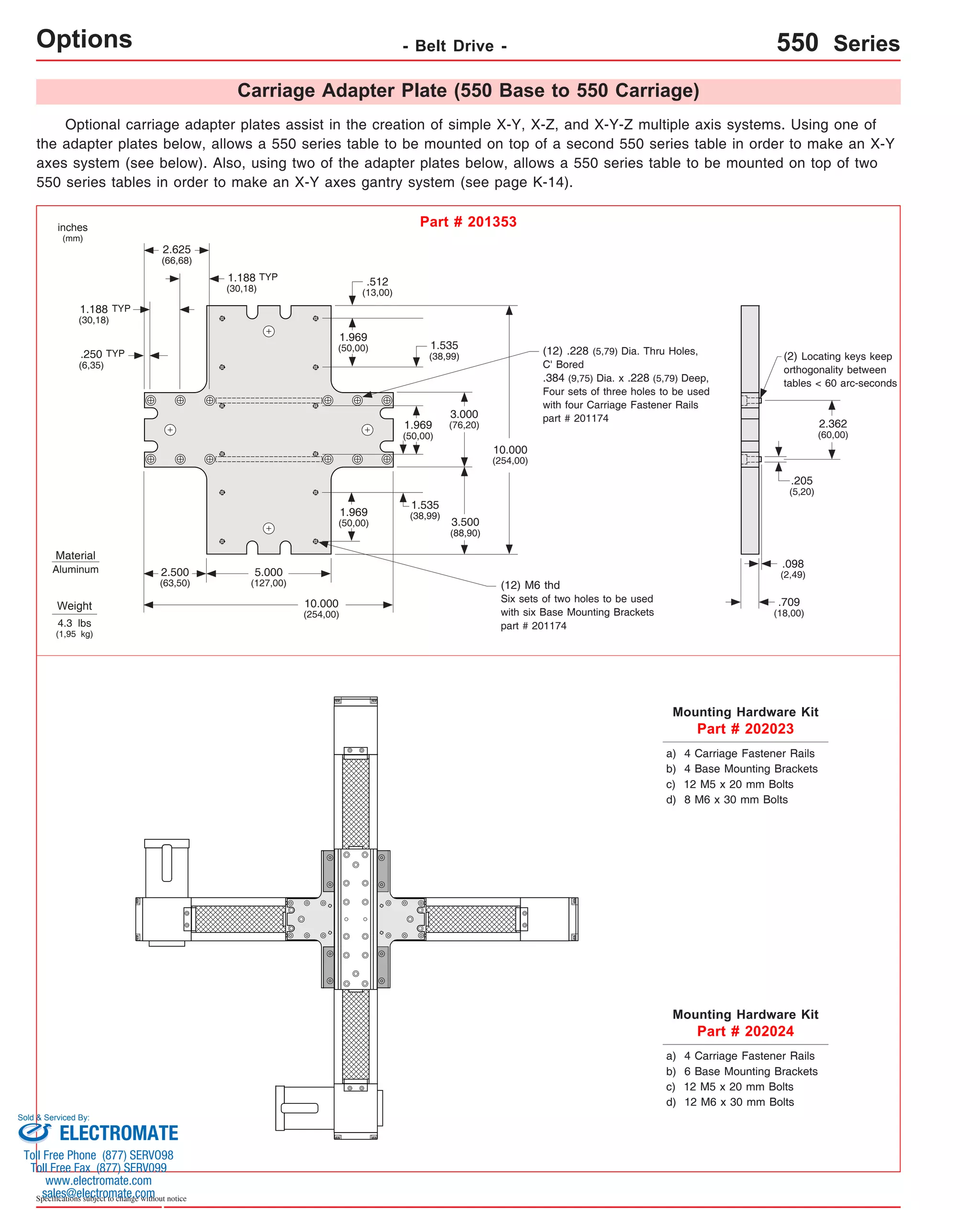
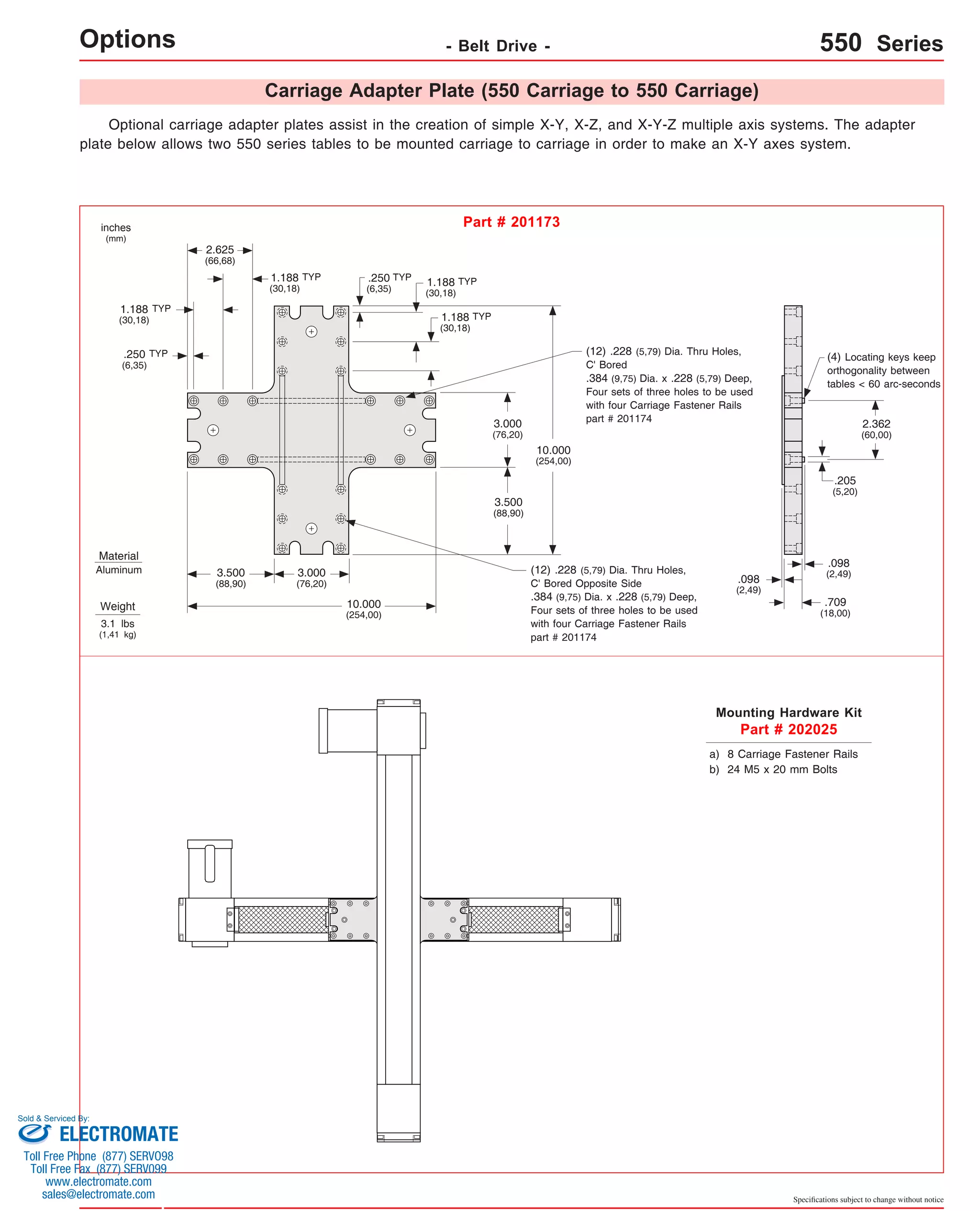
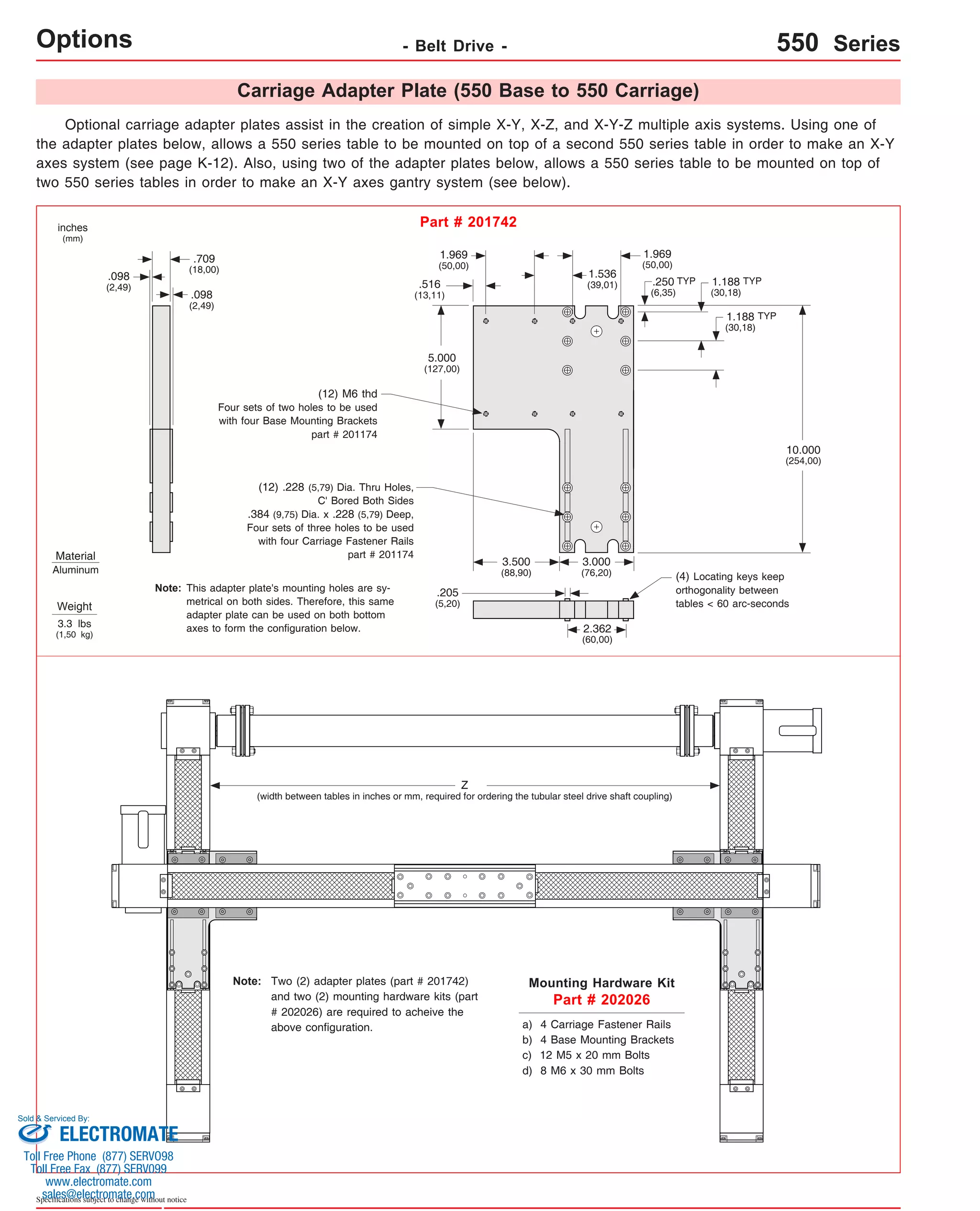
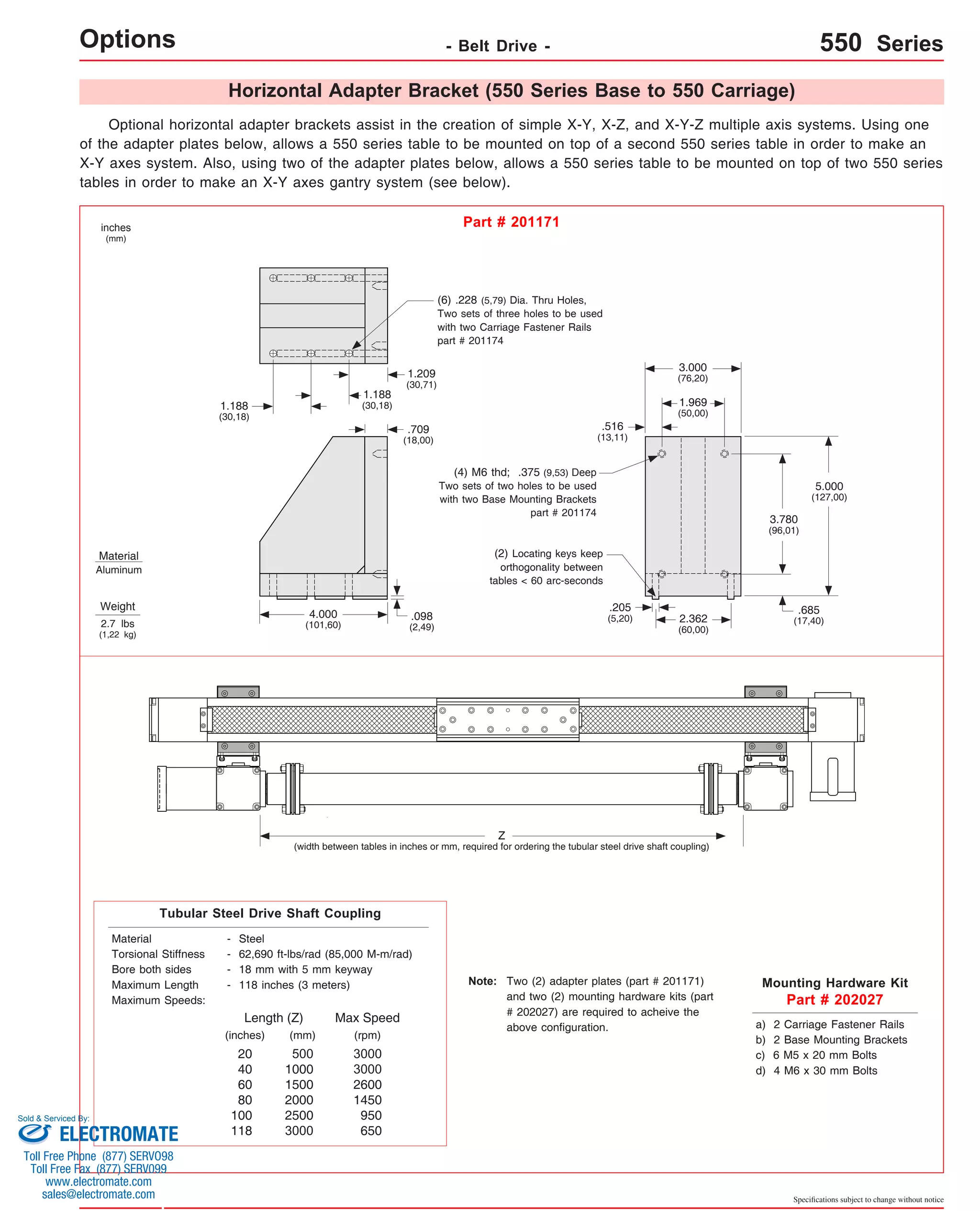
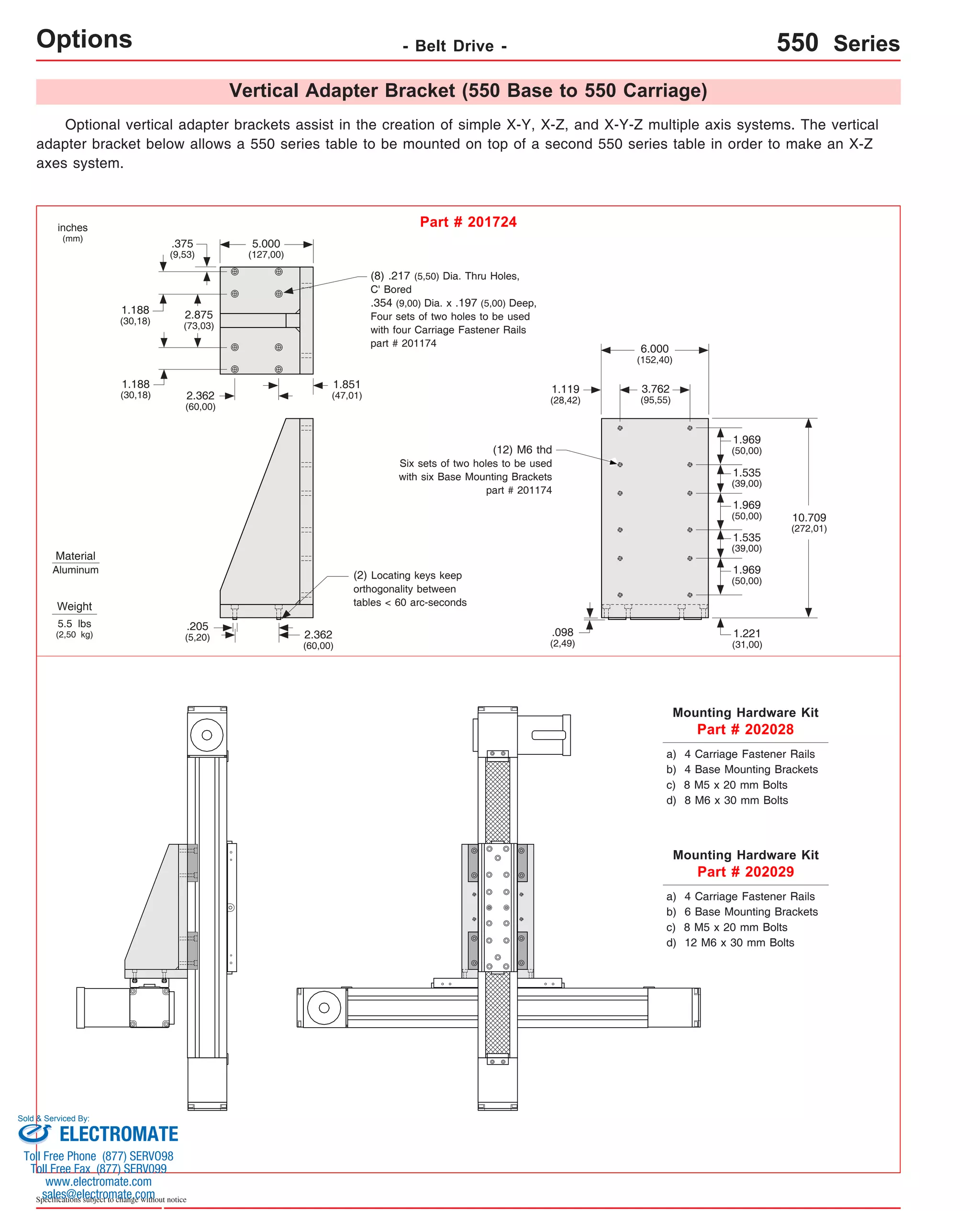

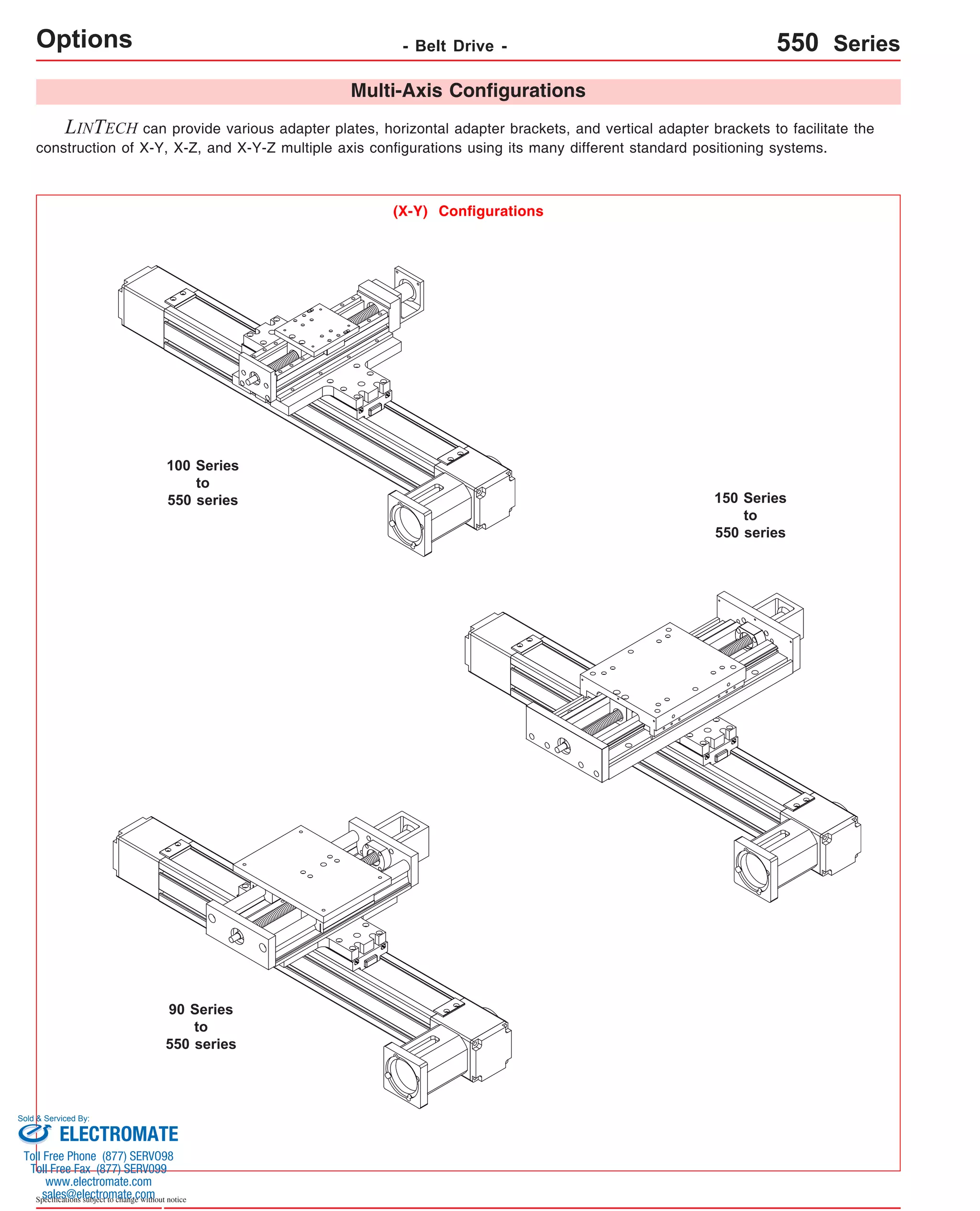
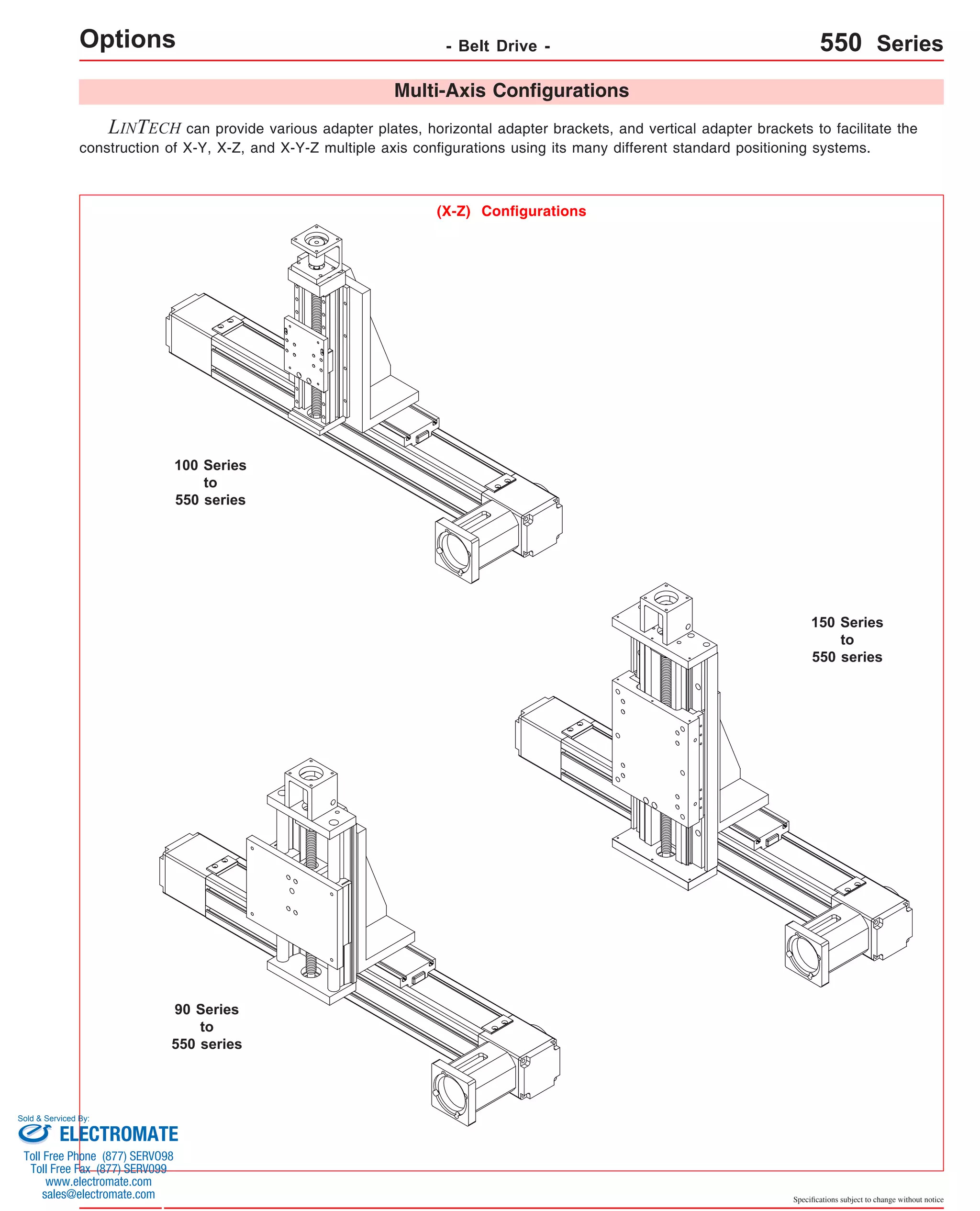
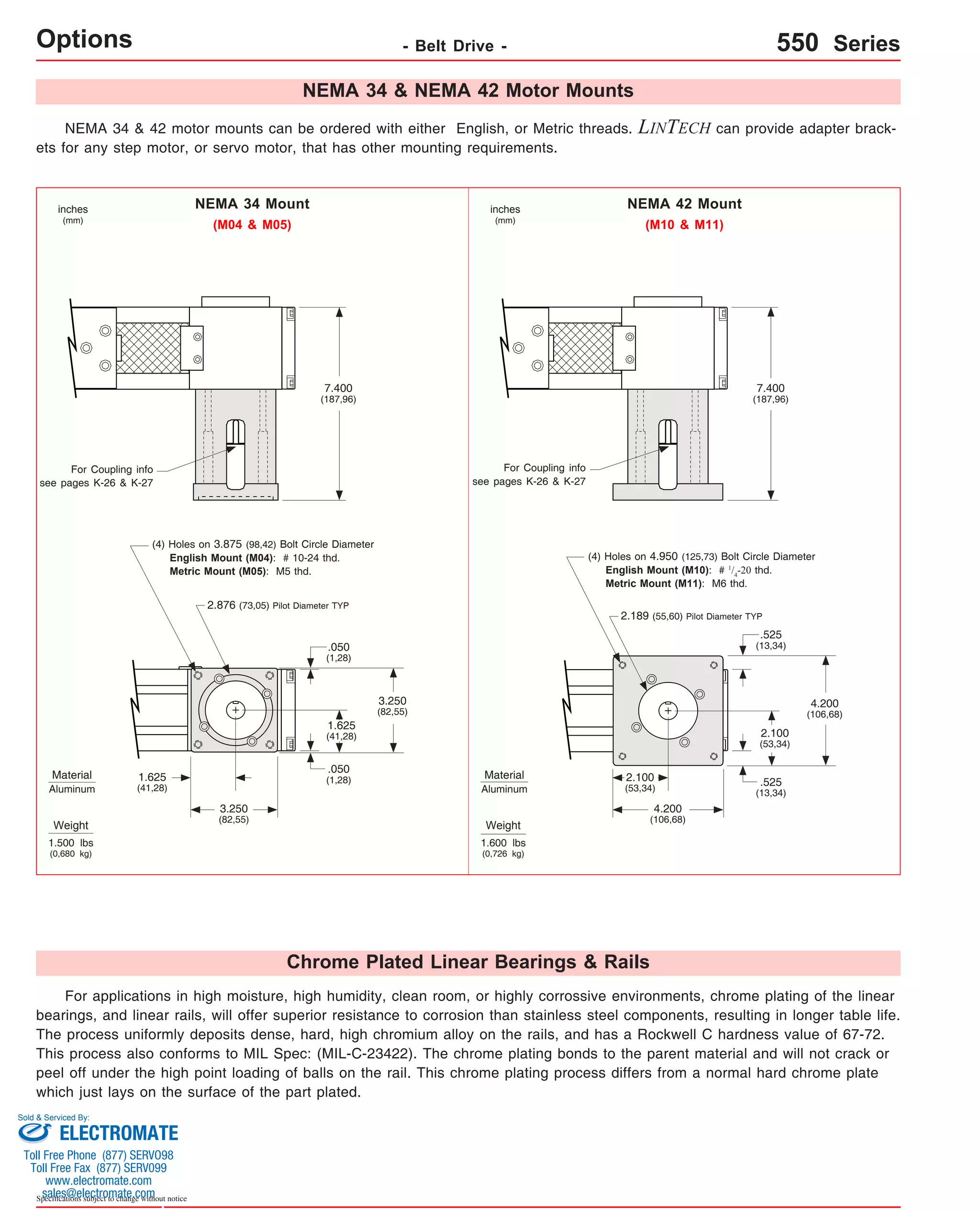
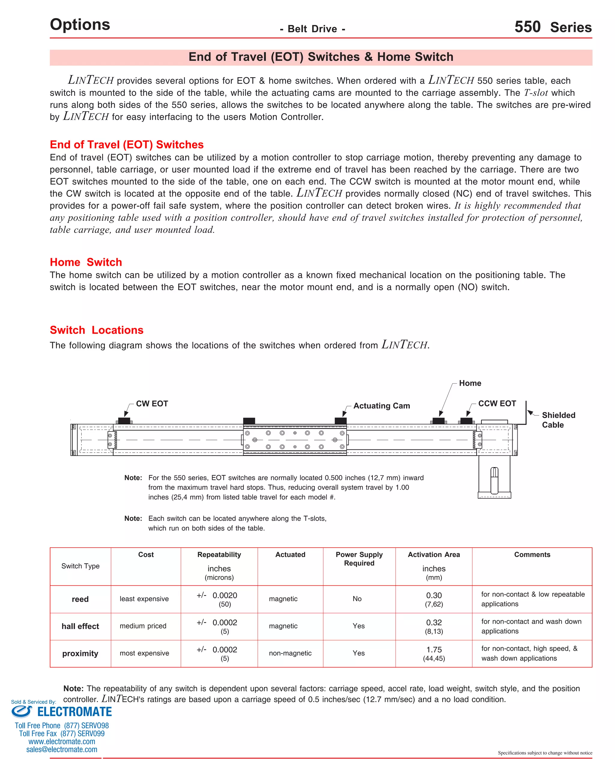
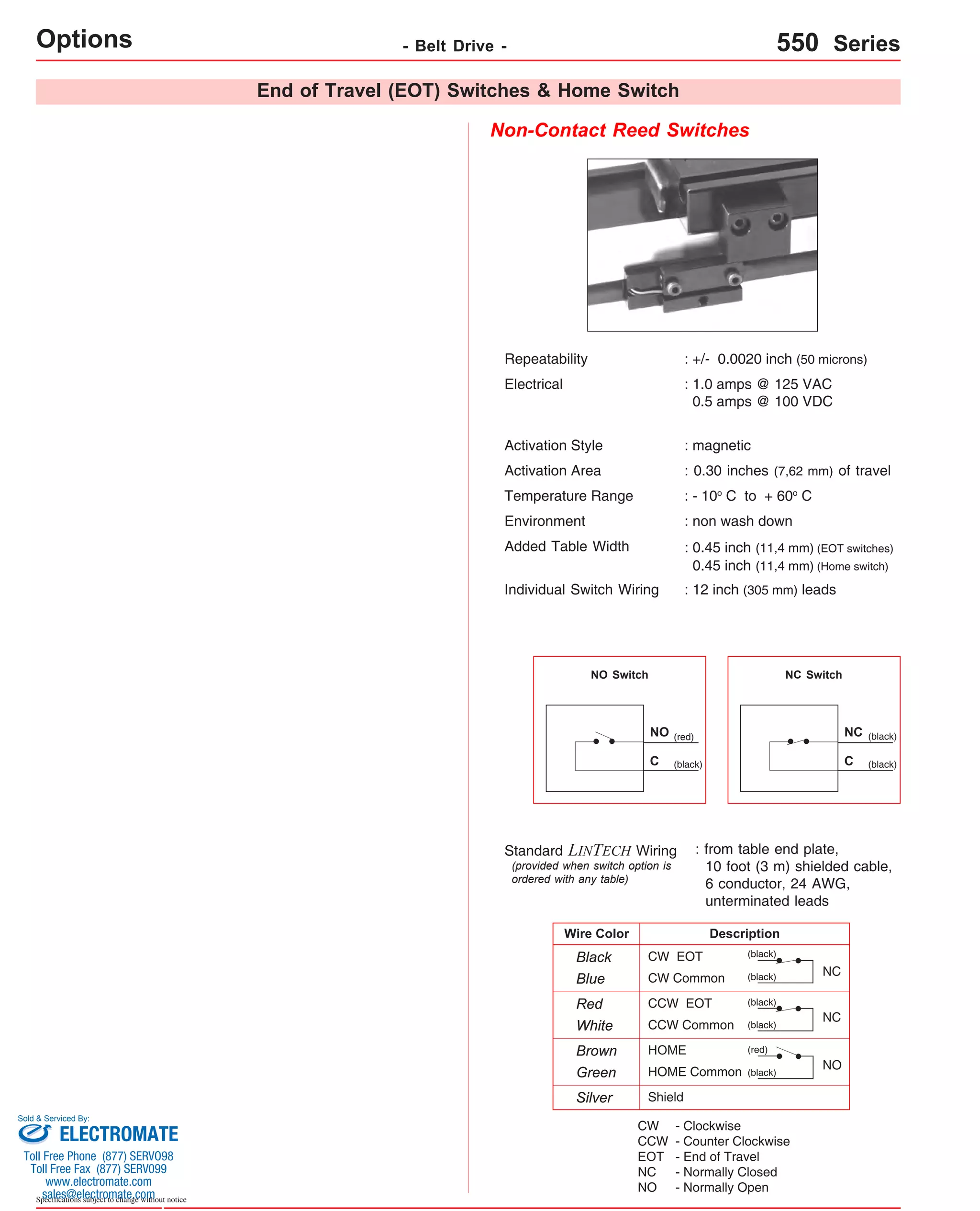
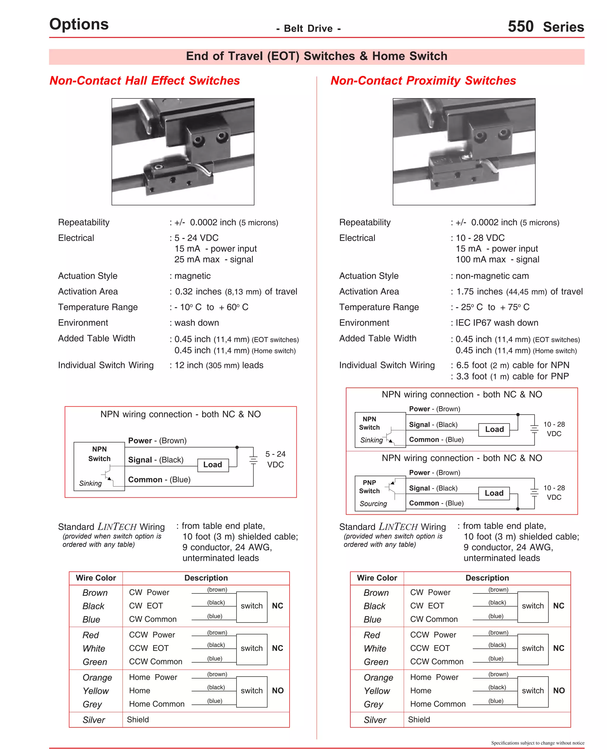
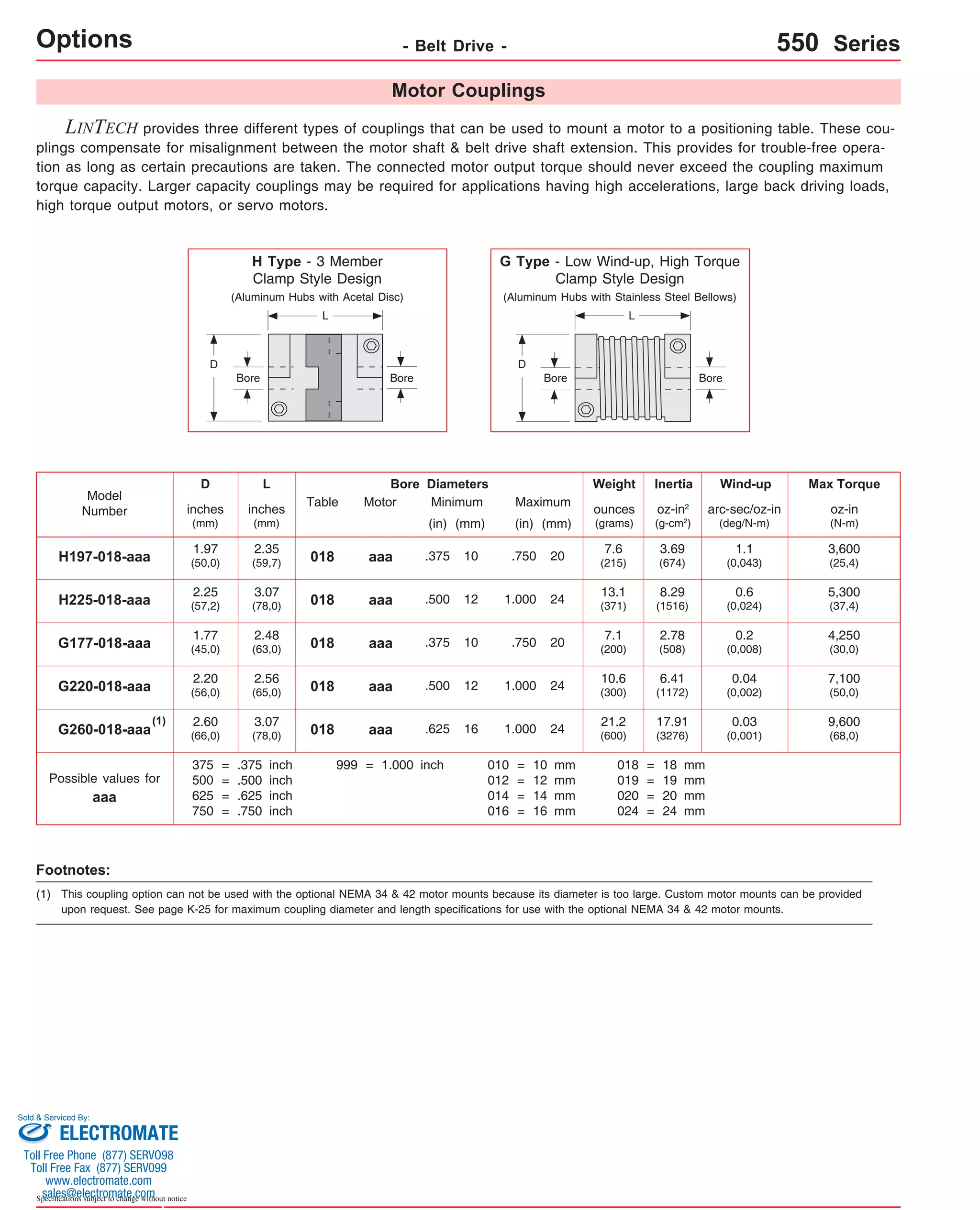
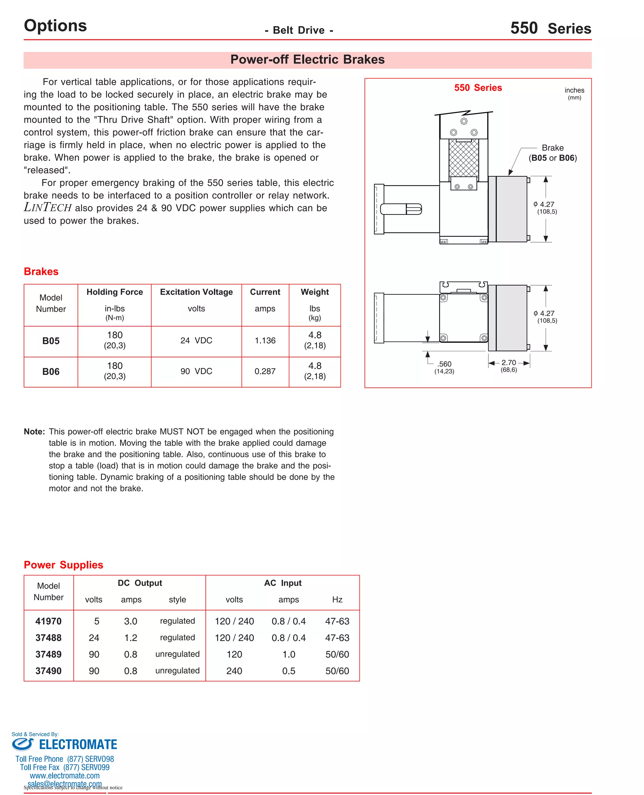
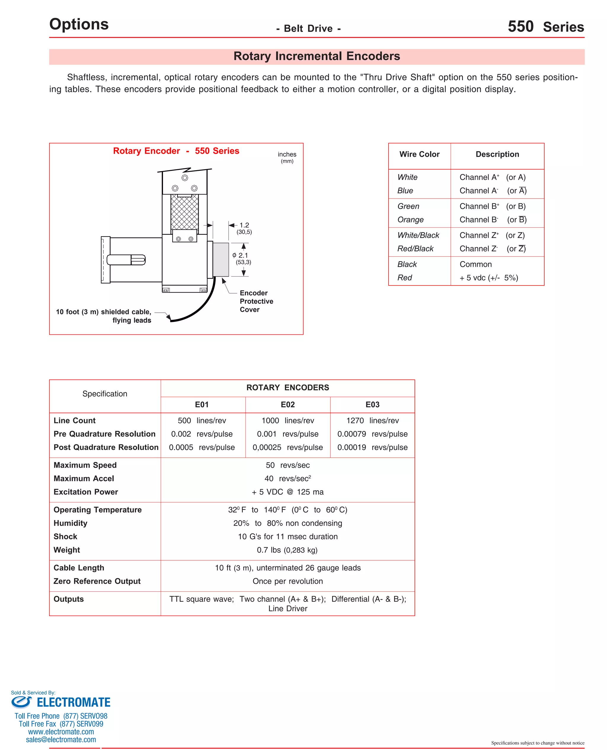

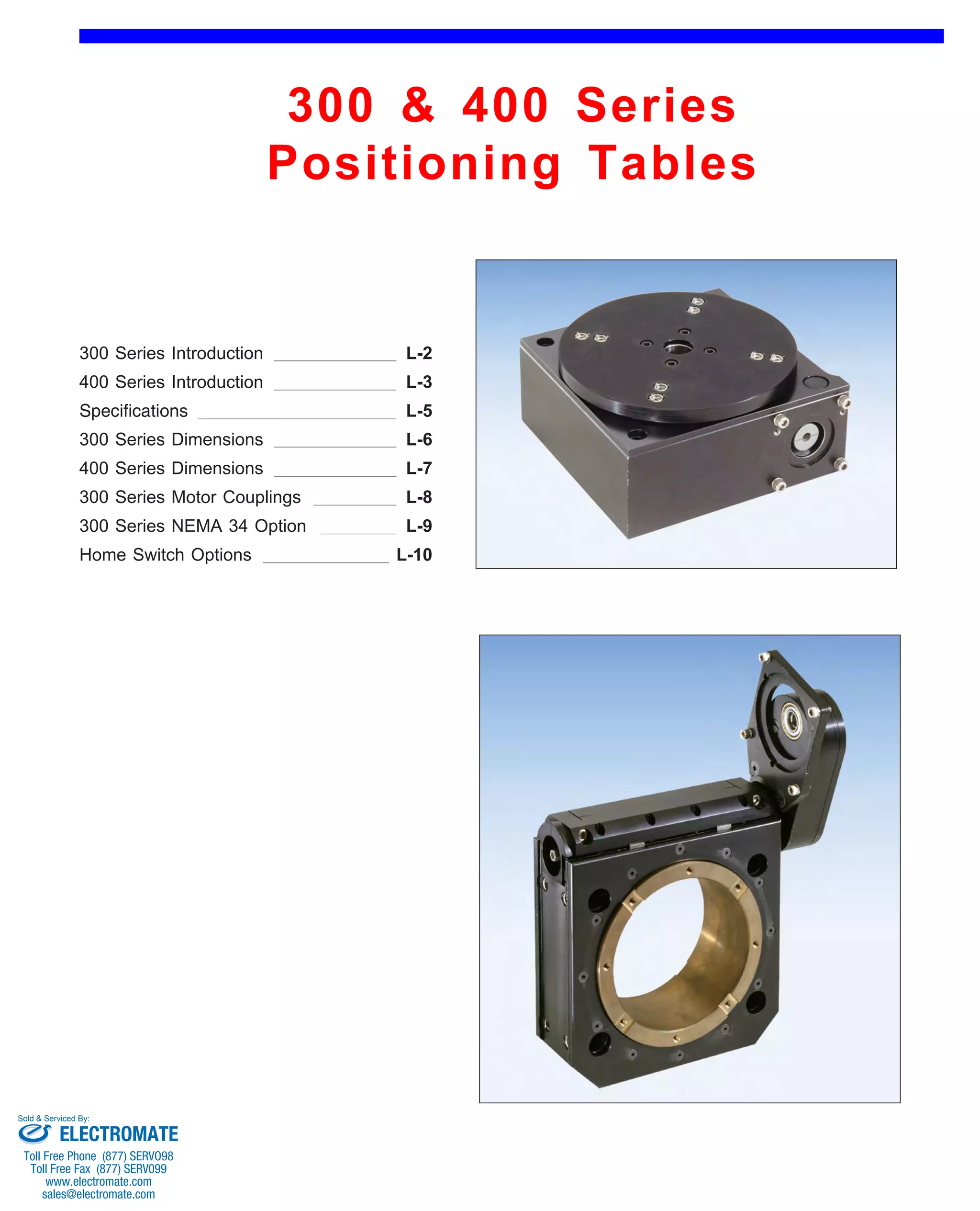
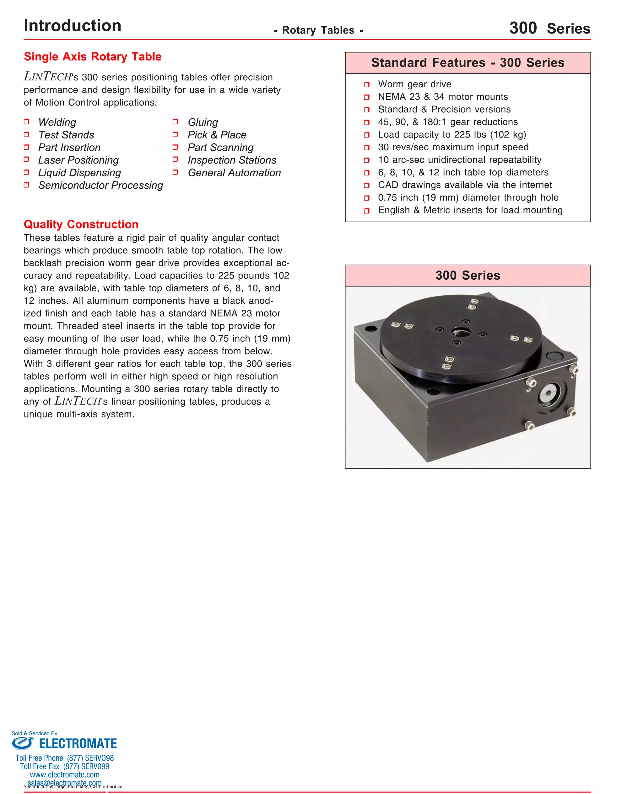
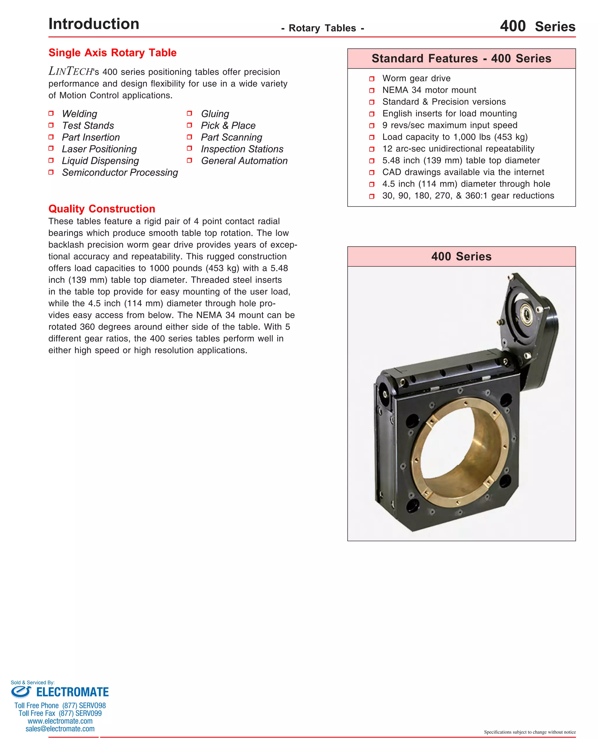
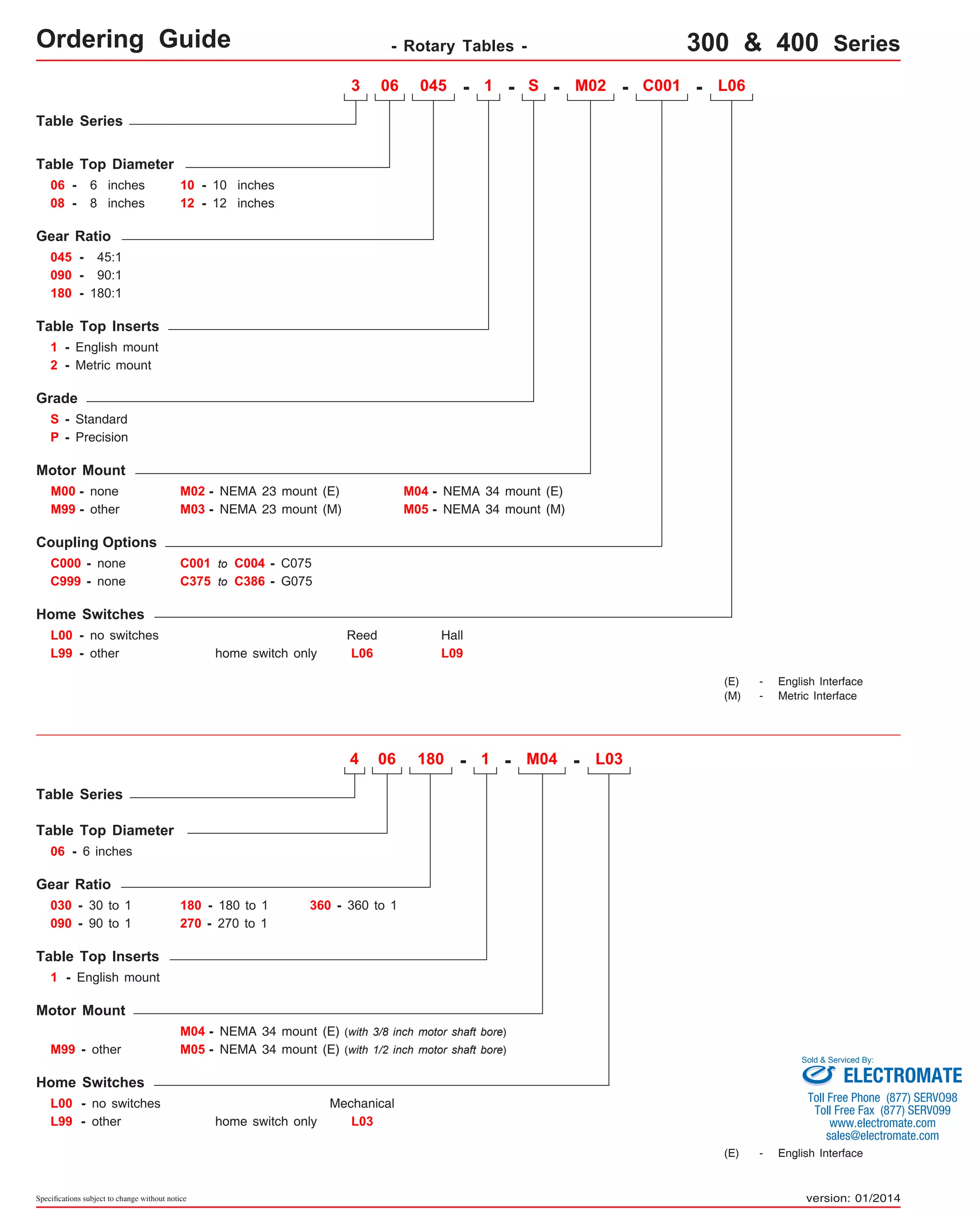


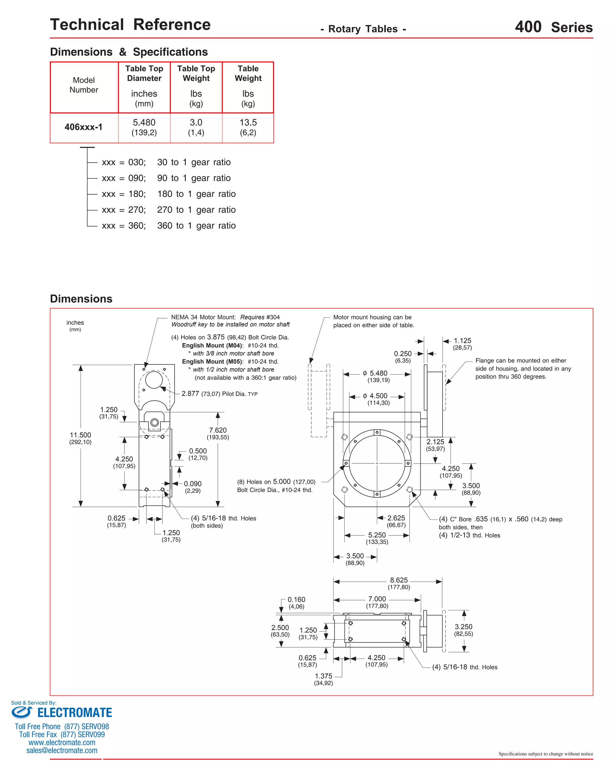
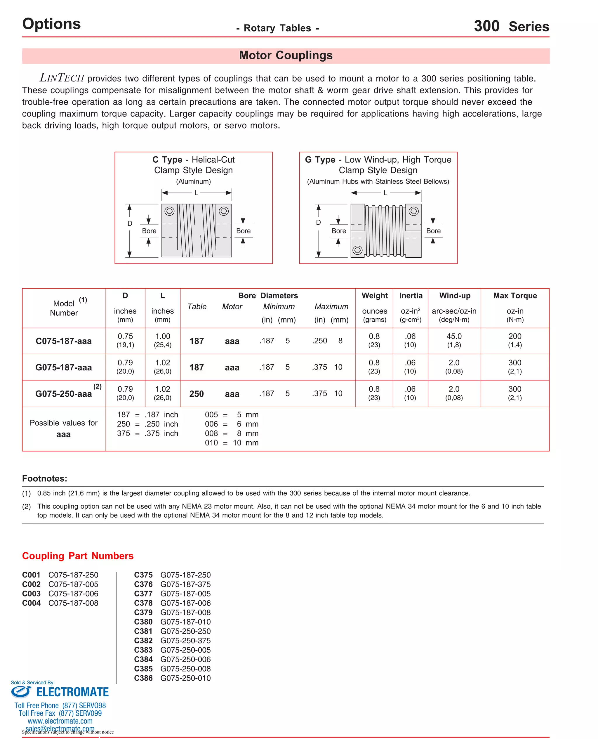
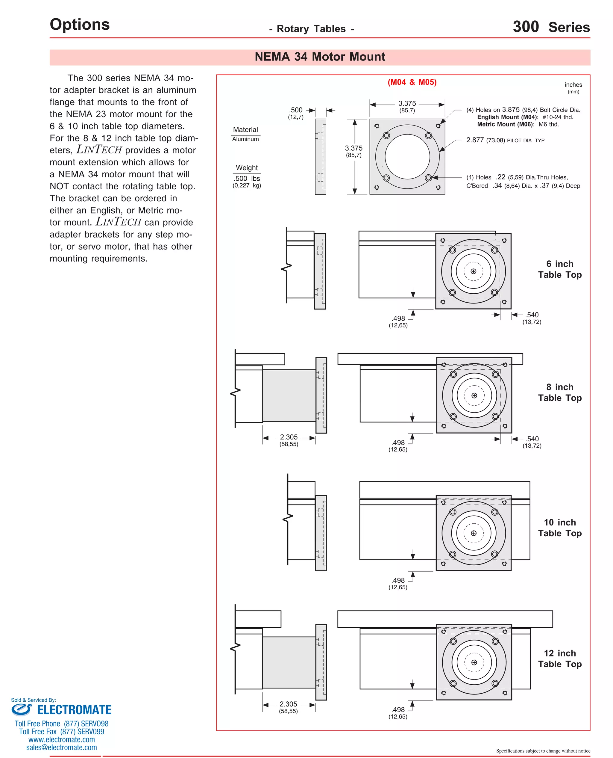
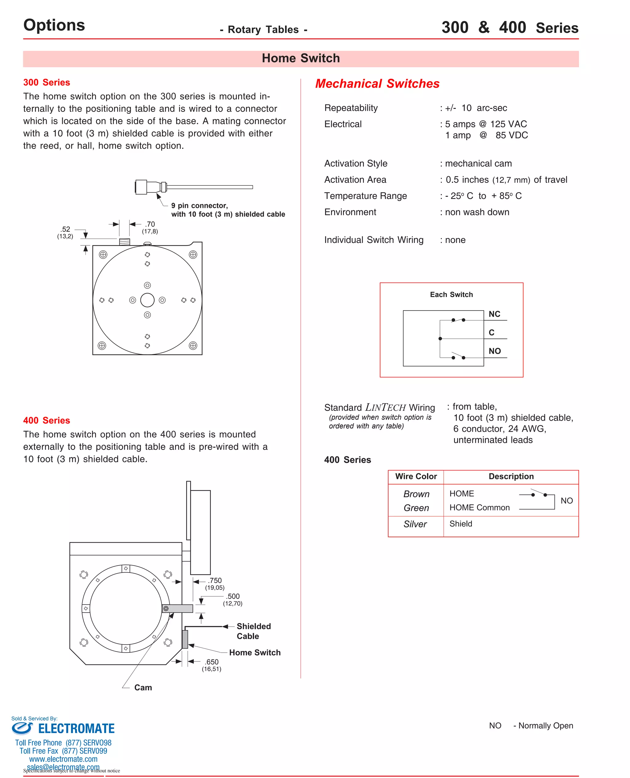
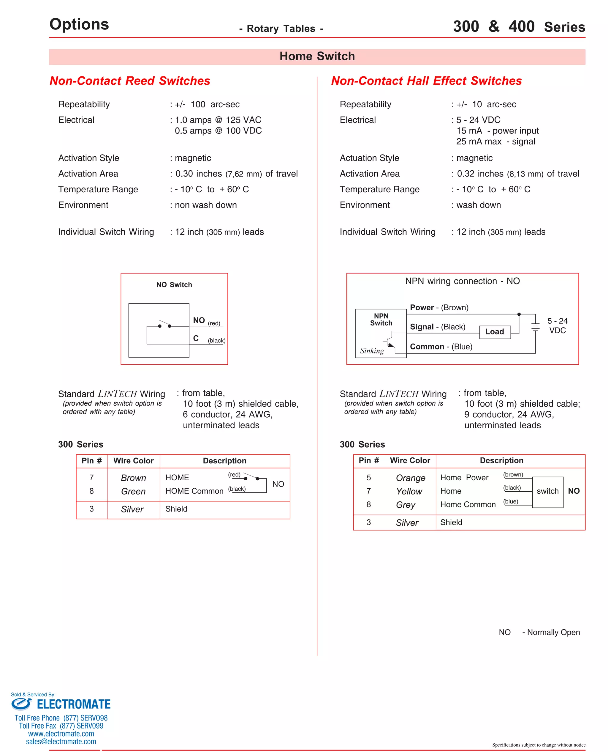
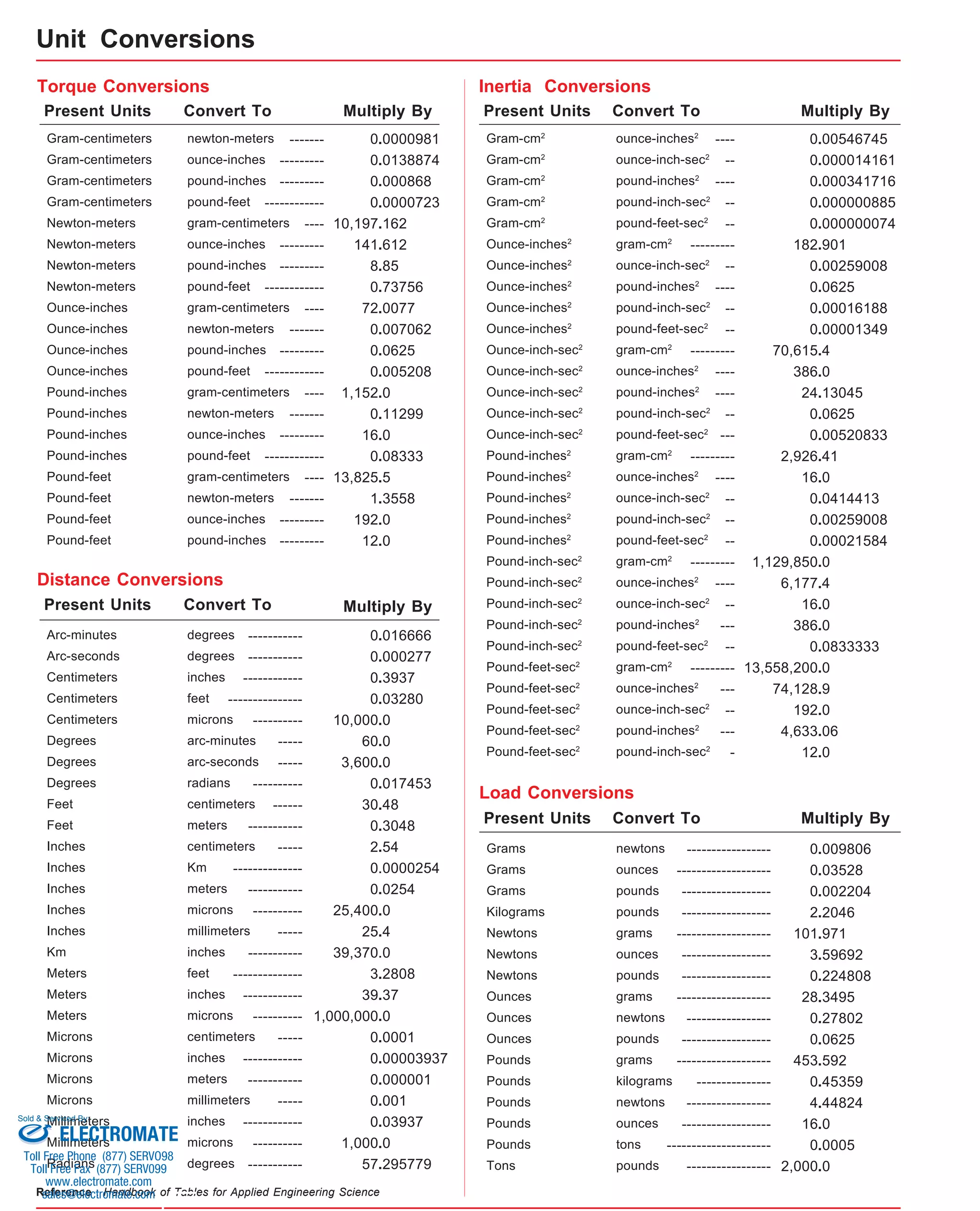

This document provides an overview and specifications for various standard and custom linear and rotary positioning systems manufactured by LINTECH. It includes specifications for several series of belt-driven and screw-driven linear positioning tables with different load capacities, travel lengths, speeds and accuracies. It also lists specifications for rotary positioning tables and provides considerations for selecting the appropriate type of positioning system for an application, such as whether accuracy, speed, load capacity or travel length is prioritized. The document indicates that LINTECH can also design and build custom positioning systems for applications where standard systems do not meet requirements.


![Vibe Coding vs. Spec-Driven Development [Free Meetup]](https://cdn.slidesharecdn.com/ss_thumbnails/vibecodingvsspecdrivendevelopment-251209105622-43f455e7-thumbnail.jpg?width=640&height=640&fit=bounds)


