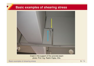
Department of Structural Mechanics
Faculty of Civil Engineering, VSB - Technical University Ostrava
Elasticity and plasticity
Theme 6
Shearing stress in
bending
• Basic relationships and conditions of solutions
• Shearing stress in chosen cross-sections
• Shear flux and shear centre
• Dimension of members in shear
• Composite beams
2 / 74
Shearing stress in beams
Basic relations and conditions of solution
b
a
+
V
V
Rbz
Raz
F
-
V
V
In bending there come up usually together with bending moments also shear
forces, which causes the shearing stress.
0
, ≠
y
z M
V
0
=
=
=
= z
x
y M
M
V
N
In the plane xz:
Plane bending: external and internal forces are in planes xy or xz – the main
planes.
0
, ≠
z
y M
V
0
=
=
=
= y
x
z M
M
V
N
In the plane xy :
3 / 74
Basic examples of shearing stress
Cracks in bridges after flood in 2002, South Czech, photo: Prof. Ing. Vladimír Tomica, CSc.
4 / 74
Basic examples of shearing stress
Cracks in bridges after flood in 2002, South Czech, photo: Prof. Ing. Vladimír Tomica, CSc.
Basic examples of shearing stress
5 / 74
Basic examples of shearing stress
Crack in the support of the concrete beam
photo: Prof. Ing. Radim Čajka, CSc.
Basic examples of shearing stress
6 / 74
Basic examples of shearing stress
Základní vztahy a předpoklady řešení
Detail of the screw connection
7 / 74
The formula of reciprocity of the shearing stresses
y
z
x
[ ]










=
z
yz
y
xz
xy
x
σ
τ
σ
τ
τ
σ
σ
sym.
Tenzor of stresses:
{ } { }T
xy
zx
yz
z
y
x τ
τ
τ
σ
σ
σ
σ =
Vector of stresses:
more topic n.8
Just 6 stresses components
S
z
d
y
d
x
d
xy
τ
yx
τ
yx
τ
xy
τ
yx
xy τ
τ = zy
yz τ
τ = xz
zx τ
τ =
similarly
Basic relations and conditions of solution
8 / 74
Basic relations for derivation of shearing stress
Shearing stress in chosen cross-sections
+y
+z
A B
T
z
( )
z
b
y
S
A,
( )
z
y
y
z
zx
xz
b
I
S
V
.
.
=
=τ
τ
statical moment of separate part of cross section
...
y
S
z
V ... Shear force in section
y
I ... moment of inertia of the whole cross section
( )
z
b ... Width of cross-section in the assessing place
Grashof formula
Cross sectional characteristics for shear stress
in bending are:
- Sy
- Iy
[ ]
3
T
part
y m
z
A
S ⋅
=
9 / 74
Shear stress in a rectangular cross section
Shearing stress in chosen cross-sections
z
y
b
h
Cross section
max
τ
o
2
Distribution of xz
τ
z
3
.
12
1
h
b
Iy =
( ) b
b z =
T
z
( ) A
V
bh
V
b
bh
h
bh
V
b
I
S
V Z
Z
z
z
y
y
z
ax
m
2
3
2
3
12
1
4
2
.
.
3
2
/
1 =
=
⋅
⋅
⋅
=
=
=τ
τ
[ ]
3
T
průr
části
y m
z
A
S ⋅
=
statical moment of separate part of cross section
...
y
S
z
V ... Shear force in section
y
I ... moment of inertia of the whole cross section
( )
z
b ... Width of cross-section in the assessing place
10 / 74
Design and assessment of rectangular cross section in
shear
Dimensioning
Assessment after Ultimate Limit
State
Design
Realisation
Dimensioning
d
req
Ed f
A
V ,
,
Rd
Ed V
V ≤
Rd
V
To make bigger section
M
k
d
f
f
γ
=
3
.
2
3
max
d
z f
A
V
≤
=
τ
d
z
req
f
V
A
.
2
.
3
3
=
1
≤
Rd
Ed
V
V
11 / 74
Shearing stress in thin-walled members
Shearing stress in chosen cross-sections
h
t
t
t w
f <<
,
,
t
h
Symmetric I
h
w
h
f
t
f
t
f
b
w
t
w (web)
f (flange)
Thin-walled beam
Open cross sections: I, U, T, C, Z Hollow box-beam sections (pipe):
12 / 74
Shear stress in I profile
Shearing stress in chosen cross-sections
Section
Wall Distribution of
z
y
Flange Distribution of
xz
τ
xy
τ
max
,
xz
τ
o
2
h
w
h
f
t
f
t
f
b
w
t
o
1
Condition of solutions:
• shearing stress is constant in the vertical
cut to the fragment of the wall (see Detail)
• is parallel to circumference of the section
xy
τ
Detail
Detail
13 / 74
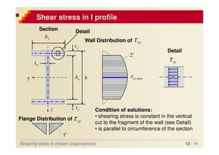
Shear stress in the wall of the I-profile
Shearing stress in chosen cross-sections
Distribution
z
y
xz
τ
max
,
xz
τ
o
2
h
w
h
f
t
f
t
f
b
w
t
z
t
I
S
V
y
y
z
x
.
.
=
τ
Basic formula:
t ... Thickness in the assessing
fragment
y
S ...statical moment of a
separate partn of the section
x
τ ... Shearing stress in the plane
perpendicular to the axis x
xz
τ
xy
τ
vertical part
horizontal part
Shearing stress in the wall xz
τ
(quadratic function)
[ ]
3
T
part
y m
z
A
S ⋅
=
14 / 74
Shear stress in the flange of I-profile
Shearing stress in chosen cross-sections
z
y h
w
h
f
t
f
t
f
b
w
t
Distribution of xy
τ
o
1
t
I
S
V
y
y
z
x
.
.
=
τ
Basic formula
Shearing stress in the flange xy
τ
(Linear function)
[ ]
3
T
part
y m
z
A
S ⋅
=
T
z
15 / 74
Maximum stress in the I-profile
Shearing stress in chosen cross-sections
Distribution of
z
y
Distribution of
xz
τ
xy
τ
max
,
xz
τ
o
2
h
w
h
f
t
f
t
f
b
w
t
o
1
( )( )
[ ]
2
max .
.
.
.
4
.
.
.
8
h
t
t
h
t
b
t
t
I
V
w
f
w
f
w
y
z
+
−
−
=
τ
0
=
z
16 / 74
Shear centre
Shear flux and shear centre
At double symmetric cross sections the resulting force goes throught the centre of
gravity, at non symmetric sections it is different – if a plane of the load is not a plane
of symmetry, than the load must go throught the shear centre A, otherwise the
member would be twisted (stress from torsion).
We obtain resulting shear forces Qf in the profile by the integration of shearing
stresses along the single walls of the open profile. They are equivalent to shear force
Vz.
+y
+z
T
A
0
h
0
h
t
t
z
V
o
45
f
Q
f
Q
x
τ
x
τ
z
V
f
Q
f
Q
2
z
f
V
Q =
17 / 74
Shear centre of the U-profile
Shear flux and shear centre
z
y T
0
h
A
z
V
f
Q
f
Q
0
b
a
w
Q
xy
τ
xy
τ
xz
τ
s
h
t
h
s
t
S f
f
y .
.
.
2
1
2
.
. 0
0
=
=
s
y
z
f
y
y
z
xy
I
s
h
V
t
I
S
V
.
2
.
.
.
. 0
=
=
τ
Flange:
Profiles U, UE, UPE - size a in tables
18 / 74
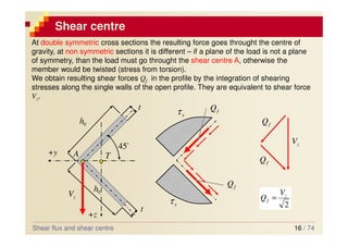
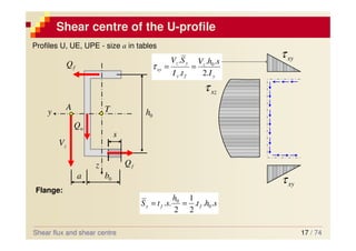
Shear centre of U-profile
Shear flux and shear centre
z
y T
0
h
A
z
V
f
Q
f
Q
0
b
a
w
Q
xy
τ
xy
τ
xz
τ
s
M
( )
[ ]
2
2
0
0
0 4
.
.
.
.
4
.
.
.
8
z
h
t
h
b
t
t
I
V
w
f
w
y
z
xz −
+
=
τ
Web
... likewise I profile
z
w V
Q =
0
.
. h
Q
a
V f
z =
Statical moments to point M → y
f
z
f
I
h
b
t
V
h
Q
a
.
4
.
.
. 2
0
2
0
0
=
=
19 / 74
Composite members
Composite members
a b
b
a b
0
≠
V
welds, screws, bolts
a
a
( ) ( )
( ) y
y
z
z
y
y
z
z
zx
z
x
I
S
V
b
I
S
V
b
b
Q
.
.
.
.
.
*
=
=
= τ
[kN/m]
a
I
S
V
a
Q
Q
y
y
z
x
x .
.
.
*
=
=
[kN]
Shear force for one
connecting member
↓
20 / 74
Questions for the exam
1. Shearing stress in bending of the rectangular
cross section
2. Shearing stress in bending of thin-walled
members, shear centre
3. Assessment of the members under shear
stress in bending
4. Composite members
Questions for the exam

shear stress in bending.pdf

  • 1.
    Department of StructuralMechanics Faculty of Civil Engineering, VSB - Technical University Ostrava Elasticity and plasticity Theme 6 Shearing stress in bending • Basic relationships and conditions of solutions • Shearing stress in chosen cross-sections • Shear flux and shear centre • Dimension of members in shear • Composite beams
  • 2.
    2 / 74 Shearingstress in beams Basic relations and conditions of solution b a + V V Rbz Raz F - V V In bending there come up usually together with bending moments also shear forces, which causes the shearing stress. 0 , ≠ y z M V 0 = = = = z x y M M V N In the plane xz: Plane bending: external and internal forces are in planes xy or xz – the main planes. 0 , ≠ z y M V 0 = = = = y x z M M V N In the plane xy :
  • 3.
    3 / 74 Basicexamples of shearing stress Basic examples of shearing stress Cracks in bridges after flood in 2002, South Czech, photo: Prof. Ing. Vladimír Tomica, CSc.
  • 4.
    4 / 74 Basicexamples of shearing stress Cracks in bridges after flood in 2002, South Czech, photo: Prof. Ing. Vladimír Tomica, CSc. Basic examples of shearing stress
  • 5.
    5 / 74 Basicexamples of shearing stress Crack in the support of the concrete beam photo: Prof. Ing. Radim Čajka, CSc. Basic examples of shearing stress
  • 6.
    6 / 74 Basicexamples of shearing stress Základní vztahy a předpoklady řešení Detail of the screw connection
  • 7.
    7 / 74 Theformula of reciprocity of the shearing stresses y z x [ ]           = z yz y xz xy x σ τ σ τ τ σ σ sym. Tenzor of stresses: { } { }T xy zx yz z y x τ τ τ σ σ σ σ = Vector of stresses: more topic n.8 Just 6 stresses components S z d y d x d xy τ yx τ yx τ xy τ yx xy τ τ = zy yz τ τ = xz zx τ τ = similarly Basic relations and conditions of solution
  • 8.
    8 / 74 Basicrelations for derivation of shearing stress Shearing stress in chosen cross-sections +y +z A B T z ( ) z b y S A, ( ) z y y z zx xz b I S V . . = =τ τ statical moment of separate part of cross section ... y S z V ... Shear force in section y I ... moment of inertia of the whole cross section ( ) z b ... Width of cross-section in the assessing place Grashof formula Cross sectional characteristics for shear stress in bending are: - Sy - Iy [ ] 3 T part y m z A S ⋅ =
  • 9.
    9 / 74 Shearstress in a rectangular cross section Shearing stress in chosen cross-sections z y b h Cross section max τ o 2 Distribution of xz τ z 3 . 12 1 h b Iy = ( ) b b z = T z ( ) A V bh V b bh h bh V b I S V Z Z z z y y z ax m 2 3 2 3 12 1 4 2 . . 3 2 / 1 = = ⋅ ⋅ ⋅ = = =τ τ [ ] 3 T průr části y m z A S ⋅ = statical moment of separate part of cross section ... y S z V ... Shear force in section y I ... moment of inertia of the whole cross section ( ) z b ... Width of cross-section in the assessing place
  • 10.
    10 / 74 Designand assessment of rectangular cross section in shear Dimensioning Assessment after Ultimate Limit State Design Realisation Dimensioning d req Ed f A V , , Rd Ed V V ≤ Rd V To make bigger section M k d f f γ = 3 . 2 3 max d z f A V ≤ = τ d z req f V A . 2 . 3 3 = 1 ≤ Rd Ed V V
  • 11.
    11 / 74 Shearingstress in thin-walled members Shearing stress in chosen cross-sections h t t t w f << , , t h Symmetric I h w h f t f t f b w t w (web) f (flange) Thin-walled beam Open cross sections: I, U, T, C, Z Hollow box-beam sections (pipe):
  • 12.
    12 / 74 Shearstress in I profile Shearing stress in chosen cross-sections Section Wall Distribution of z y Flange Distribution of xz τ xy τ max , xz τ o 2 h w h f t f t f b w t o 1 Condition of solutions: • shearing stress is constant in the vertical cut to the fragment of the wall (see Detail) • is parallel to circumference of the section xy τ Detail Detail
  • 13.
    13 / 74 Shearstress in the wall of the I-profile Shearing stress in chosen cross-sections Distribution z y xz τ max , xz τ o 2 h w h f t f t f b w t z t I S V y y z x . . = τ Basic formula: t ... Thickness in the assessing fragment y S ...statical moment of a separate partn of the section x τ ... Shearing stress in the plane perpendicular to the axis x xz τ xy τ vertical part horizontal part Shearing stress in the wall xz τ (quadratic function) [ ] 3 T part y m z A S ⋅ =
  • 14.
    14 / 74 Shearstress in the flange of I-profile Shearing stress in chosen cross-sections z y h w h f t f t f b w t Distribution of xy τ o 1 t I S V y y z x . . = τ Basic formula Shearing stress in the flange xy τ (Linear function) [ ] 3 T part y m z A S ⋅ = T z
  • 15.
    15 / 74 Maximumstress in the I-profile Shearing stress in chosen cross-sections Distribution of z y Distribution of xz τ xy τ max , xz τ o 2 h w h f t f t f b w t o 1 ( )( ) [ ] 2 max . . . . 4 . . . 8 h t t h t b t t I V w f w f w y z + − − = τ 0 = z
  • 16.
    16 / 74 Shearcentre Shear flux and shear centre At double symmetric cross sections the resulting force goes throught the centre of gravity, at non symmetric sections it is different – if a plane of the load is not a plane of symmetry, than the load must go throught the shear centre A, otherwise the member would be twisted (stress from torsion). We obtain resulting shear forces Qf in the profile by the integration of shearing stresses along the single walls of the open profile. They are equivalent to shear force Vz. +y +z T A 0 h 0 h t t z V o 45 f Q f Q x τ x τ z V f Q f Q 2 z f V Q =
  • 17.
    17 / 74 Shearcentre of the U-profile Shear flux and shear centre z y T 0 h A z V f Q f Q 0 b a w Q xy τ xy τ xz τ s h t h s t S f f y . . . 2 1 2 . . 0 0 = = s y z f y y z xy I s h V t I S V . 2 . . . . 0 = = τ Flange: Profiles U, UE, UPE - size a in tables
  • 18.
    18 / 74 Shearcentre of U-profile Shear flux and shear centre z y T 0 h A z V f Q f Q 0 b a w Q xy τ xy τ xz τ s M ( ) [ ] 2 2 0 0 0 4 . . . . 4 . . . 8 z h t h b t t I V w f w y z xz − + = τ Web ... likewise I profile z w V Q = 0 . . h Q a V f z = Statical moments to point M → y f z f I h b t V h Q a . 4 . . . 2 0 2 0 0 = =
  • 19.
    19 / 74 Compositemembers Composite members a b b a b 0 ≠ V welds, screws, bolts a a ( ) ( ) ( ) y y z z y y z z zx z x I S V b I S V b b Q . . . . . * = = = τ [kN/m] a I S V a Q Q y y z x x . . . * = = [kN] Shear force for one connecting member ↓
  • 20.
    20 / 74 Questionsfor the exam 1. Shearing stress in bending of the rectangular cross section 2. Shearing stress in bending of thin-walled members, shear centre 3. Assessment of the members under shear stress in bending 4. Composite members Questions for the exam