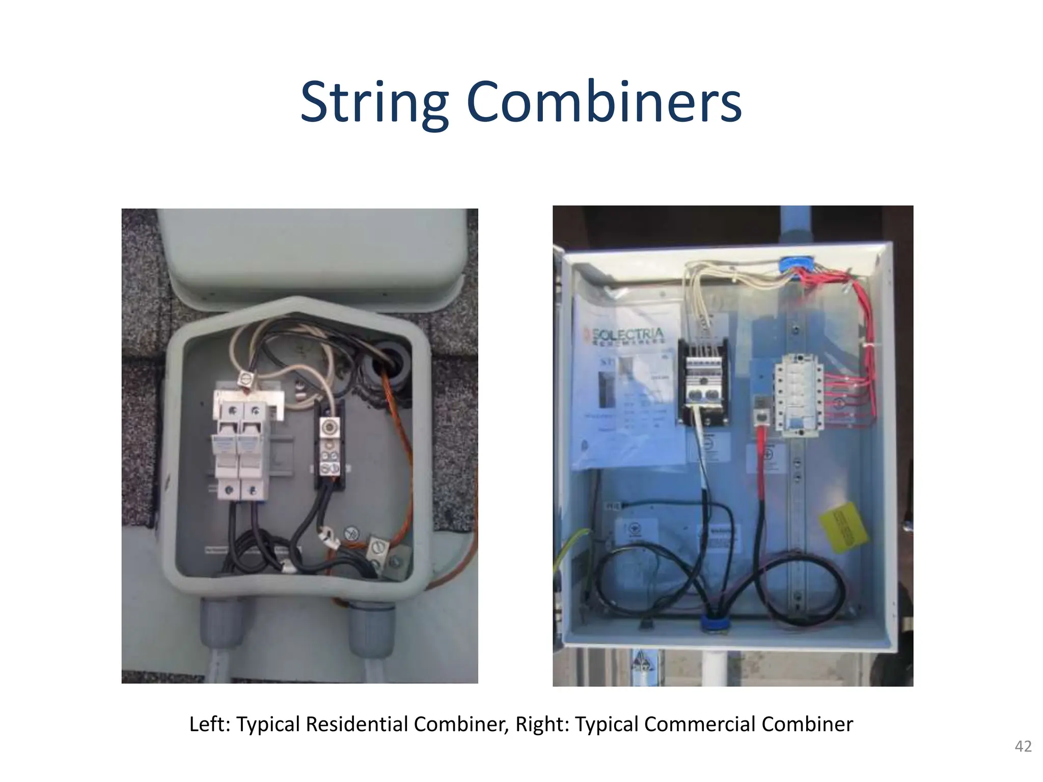
Solar Photovoltaic (PV) Fire Safety Training
Matt Piantedosi
Senior Assoc. Engineer & Master Electrician
The Cadmus Group Inc.
Matt.Piantedosi@cadmusgroup.com
Tony Granato
Lieutenant and CT Certified Fire Instructor
Connecticut E2 Journeyman Electrician
Tonyg68@cox.net
Nate Hausman, Project Manager
Clean Energy States Alliance
(802)223-2554
Nate@cleanegroup.org
www.cesa.org 2
• The New England Solar Cost-Reduction Partnership is a
consortium of five New England states and the Clean Energy
States Alliance (CESA), working to drive down the non-
hardware “soft” costs for solar PV electricity systems. The
Partnership consists of the following state agencies:
 CT: Connecticut Green Bank
 MA: Massachusetts Department of Energy Resources and the
Massachusetts Clean Energy Center
 NH: New Hampshire Office of Energy and Planning
 RI: Rhode Island Office of Energy Resources and Rhode Island Commerce
Corporation
 VT: Vermont Public Service Department
• CESA, a national, nonprofit that advances state and local
efforts to implement smart clean energy policies and
programs, coordinates the Partnership.
New England Solar Cost-Reduction Partnership
SunShot Initiative Rooftop Solar Challenge
• The New England Solar Cost-Reduction Partnership is funded through the
U.S. Department of Energy SunShot Initiative Rooftop Solar Challenge II
program.
• The SunShot Initiative is a national collaborative effort to make solar
energy cost-competitive with other forms of electricity by the end of the
decade.
• Rooftop Solar Challenge aims to reduce the cost of rooftop solar energy
systems through improved permitting, financing, zoning, net metering, and
interconnection processes for residential and small commercial PV
installations.
• The New England Solar Cost-Reduction Partnership is the only Rooftop
Solar Challenge II award for New England.
Solar Photovoltaic (PV)
Safety for Firefighters
Clean Energy States Alliance
Matt Piantedosi
Tony Granato
Winter/Spring 2016
About this presentation…
The views and opinions expressed in this presentation by the instructors are based upon their
own experiences and understanding of the topic. They do not necessarily reflect the position
of Cadmus, US DOE, CESA, or the participating states. Examples based on experiences are only
examples. They should not be utilized in actual situations.
About Matt Piantedosi
• Senior Associate Engineer, Solar PV Inspector
– The Cadmus Group
• BS Electrical Engineering
– Western New England College
• Inspected over 500 residential/commercial PV systems
• Licensed Electrician in MA, NH, RI, and CT
• Working in the trade for over 16 years
• IAEI – Boston Paul Revere Chapter
– Executive Board Member
6
About Tony Granato
• Hometown: South Glastonbury, Connecticut
• 24 years career fire service
– 8 years at the rank of Lieutenant
• Certified Connecticut Fire instructor
• Licensed Connecticut Electrician
7
Outline
• Photovoltaics 101
– Introduction to Photovoltaics & Electrical Theory (11)
– Recognizing PV Systems and Components (37)
– PV System Operation (59)
– PV System Common Labels (64)
• PV Fire Safety
– Planning, Size Up, and Tactical Considerations (80)
– Disconnecting Methods & Rapid Shutdown (95)
– Extinguishing a PV Fire/Hose Stream (128)
– Personal Protective Equipment (PPE) (135)
– Alternative Light Sources (140)
– Electrical Hazards (147)
– Other Hazards (171)
8
Photovoltaics 101
• The sun produces enough
energy in 24 hours to supply
our entire planet for over 4
years
• Solar technology rapidly
evolved following the 1970’s
era energy crisis
• Solar energy is renewable,
pollution and noise free
10
“Photovoltaic”… what does it mean?
• A method of converting solar energy into direct
current electricity using semiconducting materials
that exhibit the “photovoltaic effect”
• Photo = Light
• Voltaic = Electricity
11
“Photovoltaic Effect”
• The ”photovoltaic effect” is the creation of voltage or
electric current in a material upon exposure to light.
• In 1839 French scientist Edmond Becquerel discovered
the “photovoltaic effect” while experimenting with an
electrolytic cell made up of two metal electrodes placed
in an electricity conducting solution, electricity
generation increased when exposed to light.
12
What is the difference between AC and DC
Alternating Current (AC)
• The direction of current
flowing in a circuit is
constantly being reversed back
and forth.
• The frequency of repetition of
this current is 60 Hertz (North
America). The direction of the
current changes sixty times
every second.
• Power from grid is AC
13
What is the difference between AC and DC
Direct Current (DC)
• The electrical current is
only flowing in one
direction in a circuit.
• Photovoltaic modules are
DC sources of power.
14
PV Cells
• PV cells are thin layers of
silicon or amorphous
silicon
• Layered with Boron and
Phosphorous.
• Boron needs an electron,
Phosphorous has one.
• Sunlight photons makes
the electrons move.
• Creates .5V/cell
15
How solar cells become a solar array
• Multiple PV cells are
connected and
become a Module.
16
How do they work?
• Specifications unique to
make/model
• Current-limiting power source
– Will never produce more current
than their short-circuit current
(Isc) rating
• Strung together in series to
produce greater voltages
– Similar to a DC battery
• Power depends on sun exposure and temperature
• Lower temperature, higher voltage
17
Nameplate rating on a typical PV module.
• A typical module: 50-72 cells measuring 5’x3’, produces 20-
40V and 100-350 watts
• Residential systems commonly produce up to 600VDC per
string
• Commercial can be up to 1000VDC per string
• A 20 module array can produce over 6,000 watts and weigh
about 1,000 lbs.
• Constructing the array over 420 square feet of roof space
produces an additional 2.5 lbs./square foot dead load
18
How solar cells become a solar array
• Modules are connected
in series and to increase
voltage and become
Strings.
19
How solar cells become a solar array
• Strings are tied into each
other in parallel to
increase amperage and
become an Array.
20
Utility-Interactive
Central Inverter System
21
Watts = Amps x Volts
Series - parallel - series/parallel
22
Types of PV Modules
23
Crystalline
Solar Laminate
Frameless
Thin Film Solar Shingles
PV systems can be anywhere
Residential- Single family A whole neighborhood
24
Many Fire Stations in the US have PV
systems installed on their roofs
25
Things are not always what
they look like
26
No guarantee you’re walking on an
asphalt shingle roof
27
Examples of Solar Shingles
28
Examples of Solar Shingles
29
Examples of Solar Shingles
30
31
Be aware of all roof covering materials
32
Combinations of different systems
Solar PV and
Thermal Systems
33
Solar Thermal System
34
Typically 2-6 panels
Insulated piping coming from
panels (as opposed to wiring) –
typically copper
Solar thermal systems do not pose the same risk as solar photovoltaic systems.
They typically contain a loop of water/glycol in the rooftop collectors, however there may be a scalding hazard.
Solar Thermal System
35
Thermal piping can be
wrapped with insulation
Solar Thermal System
36
Recognizing PV Systems
and Components
Modules
38
Roof-mounted residential
Roof-mounted commercial
Parking areas
Building integrated shingles
Ground-mounted
Building integrated walls
39
Typical pitched-roof mounting
• Panels are secured using an
aluminum racking system
• Racking is secured to roof
with lag screws drilled into
structural rafters
• Mounting is designed to
withstand wind loads for
installation area
requirements – making them
very difficult to remove
40
Typical flat-roof mounting
41
String Combiners
42
Left: Typical Residential Combiner, Right: Typical Commercial Combiner
Inverters
• Convert DC power to AC to match
building/grid electrical system
• 3 types of inverters:
– Central Inverter
– String Inverter
– Microinverters
• All types stop converting power when utility
power shuts down
43
Central Inverter System
• Larger inverters
• Typically located
remotely from array
• Most-common for
large-scale ground-
mount or commercial
rooftop systems
5/5/2024 44
String Inverter System
• Mid-sized inverters
• Typically located adjacent to
array on commercial rooftop
systems
• Most-common type for
residential rooftop systems,
inverter will typically be
located in basement or
outside
5/5/2024 46
Microinverter System
• Mini inverter under each
module
• Most-common type for
residential rooftop systems
• Typically not found on large
commercial systems
• Minimum DC exposure
5/5/2024 49
Utility-Interactive AC (Microinverter) System
50
Courtesy of Newport Solar
Utility-Interactive Central Inverter System
With DC Optimizers
53
Solar Optimizers
54
Disconnects
55
Disconnect switches can be integral to inverters or located remotely.
Electric Panels
56
Electrical panels can be used to combine multiple inverter outputs or to connect solar to the grid.
kWh Production Meters
57
PV systems may contain a production meter in addition to the existing utility meter
Data Acquisition Systems (DAS)
58
Larger PV systems may contain a DAS, that will remotely monitor power production.
PV System Operation
• Inverter monitors grid voltage/power quality
– UL 1741 requires inverter to shut off within fraction of a second if power goes out of
range, or completely off
– Inverter will remain off until it detects 5 minutes of continuous power
– Most PV systems today do not contain batteries or energy storage
59
DC
COMBINER
DC
DISCONNECT
AC
DISCONNECT
INVERTER
PV System Operation
60
DC
COMBINER
DC
DISCONNECT
AC
DISCONNECT
INVERTER
• During production times, power goes to grid if not completely used behind the
meter
– Typically there is no onsite energy storage (today)
PV System Basics
61
DC
COMBINER
DC
DISCONNECT
AC
DISCONNECT
INVERTER
• At night, electricity is supplied by grid
Energy Storage Systems
(Battery Banks)
• Not common for most PV
systems
• Lead acid batteries are used to
store power produced.
• Newer technology -lithium ion
batteries (Tesla Powerwall)
• Charge Controllers will also be
present with Battery banks
62
PV system battery hazards
• Batteries can give off gas, both
Oxygen and Hydrogen
• They should be in well
ventilated areas with no
combustibles present
• Can be located in basements,
sheds, crawl spaces
• SCBA required for fires involving
batteries
63
PV System Common
Labels
PV System Labeling
65
690.31(G)(3)
DC Raceway Label
690.13(B)
PV System
Disconnect
690.53
DC Power Source
690.54
AC Power
Source
690.17
Disconnect Line/Load
Energized
705.12(D)(3)
Multiple Sources
705.12(D)(2)(3)(b)
PV Breaker
“Do Not Relocate”
690.56(B)
Service Disconnect
Directory
PV System Labeling
66
PV System Labeling
67
DC Raceway Label
NEC Article 690.31(G)(3)
• On or inside a building
– Minimum 3/8” CAPS
on Red
68
Required on all DC raceways, every 10 feet.
69
PV System Disconnect
NEC Article 690.13(B)
70
The utility may require specific wording on an AC disconnect.
Article 690.13(B) still applies. It is important that this is not confused with the Service Disconnect.
PV System Disconnect
NEC Article 690.13(B)
71
The correct way: Label identifying disconnect as Solar PV disconnect.
Disconnect Line/Load Energized
NEC Article 690.17(E)
72
ELECTRIC SHOCK HAZARD
DO NOT TOUCH TERMINALS.
TERMINALS ON BOTH THE LINE
AND LOAD SIDES MAY BE ENERGIZED IN THE
OPEN POSITION.
DC Power Source
NEC Article 690.53
73
Maintenance label showing DC system properties.
AC Power Source
NEC Article 690.54
74
Maintenance label showing AC system properties.
Dual Power Sources
NEC Article 705.12(D)(3)
75
Warning label indicating multiple sources of power present.
“Do Not Relocate”
NEC Article 705.12(D)(2)(3)(b)
76
INVERTER OUTPUT CONNECTION;
DO NOT RELOCATE
THIS OVERCURRENT DEVICE
Maintenance label for electrical connection in panelboard.
AC Combiner Panel
NEC Article 705.12(D)(2)(3)(c)
77
THIS EQUIPMENT FED BY MULTIPLE SOURCES.
TOTAL RATING OF ALL OVERCURRENT DEVICES,
EXCLUDING MAIN SUPPLY OVERCURRENT DEVICE,
SHALL NOT EXCEED AMPACITY OF BUSBAR.
Maintenance label for electrical connection in panelboard.
Service Disconnect Directory
NEC Article 690.56(B)
78
Inverter Directory
NEC Articles 690.15(A)(4)/705.10
79
Planning, Size Up, and
Tactical Considerations
80
Pre-plan development considerations:
• Buildings with installed solar PV systems
• Coordination with building department
• FMO Involvement in permit process?
• Maintain a record of buildings containing PV?
• Company training and walk through
• Dispatch center CAD entries
81
• After the initial size up,
consider the following
– Is there a PV system
present on the
structure/property?
– A complete 360 is
important to get a look at
all sides and roof
• What type of system is
it?
– PV, Thermal, integrated
82
83
Meter and AC
disconnect located
on “D” side
Array installed right up
to ridge line with no
setbacks, will not allow
roof ladder hooks to sit on
roof
84
Roof has solar shingles
with metal decking
“C” side of building across the street
PV inverters in
basements
Meter and PV A/C
disconnect “B/C” corner
• Is the system
involved in a fire? If
yes, what are the
appropriate actions?
85
• Proper hose stream selection and safe distances
for applying water to burning PV systems
• What do we have for roof access?
• Aerial or ground ladder operations (setbacks at ridge)
86
• Vertical ventilation might not
be an option depending on
PV system location
• Horizontal Ventilation might
be the best and only choice
87
• Where are the disconnects located?
– Interior (garage/basement) or exterior
• Do we have access to secure the disconnects?
88
89
• Lock out tag out
• Utilize LOTO procedures when disconnects or
other power sources are secured
• This is NOT DIY work!
• Consider notification to
Solar contractor for
assistance
– Look for labeling
– Information will also be
on electrical/building
permit
• Labeling may or may not
be present or legible
90
91
Residential Example: House containing PV on B and D sides.
92
Residential Example: PV inverter and AC disconnect located on B side.
93
Example of ground-mount array, large
Inverter and disconnects located remotely.
94
Ground-mount array near highway.
Disconnecting Methods
and Rapid Shutdown
Will this make the PV system safe for
operations?
95
Options for Shutting Down
96
• Covering panels with tarps
• Shutting off all accessible
disconnects
Utilizing Tarps
• May work on small residential systems
• Not practical for large PV systems
• UL test summary:
97
Utilizing foam
to cover modules
• UL performed a test with foam on a cloudy day
– After 10 minutes the foam slid off the glass
– UL concluded foam was not an effective method to block sun
98
Disconnects
• May be effective method to de-energize system
• Various system types
– Some disconnects DO NOTHING
– Can be in multiple locations
99
AC Microinverter System
• What will happen if I shut off the main disconnect?
– Conductors will be energized only under modules
– All AC electrical circuits/devices will be de-energized
100
AC Microinverter System
• What will happen if I shut off the main?
102
Courtesy of Enphase Energy
48 Vdc max 208-240 Vac
Central Inverter System
(Most Common)
103
Central Inverter System
(Most Common)
• What will happen if I shut off the main?
– All AC electrical circuits/devices de-energized
– AC conductors up to inverter de-energized
– DC conduit inside building still energized
– Rooftop DC conduit still energized
The following example assumes the PV system is connected to the main
panelboard. Care should be taken, as this is not always the case and the PV
system may have its own disconnect located remotely from the main breaker.
104
Central Inverter System
(Most Common)
105
• What will happen if I shut off the main?
– AC circuits throughout building will be de-energized if PV breaker is in main panelboard
Central Inverter System
(Most Common)
106
• What will happen if I shut off the main and DC disconnect?
– AC circuits throughout building will be de-energized if PV breaker is in main panelboard
– DC will still be energized between inverter and array
Central Inverter System
(Most Common)
107
• What will happen if I shut off the main and DC combiner disconnect?
– AC circuits throughout building will be de-energized if PV breaker is in main panelboard
– DC between inverter and combiner may be de-energized in 5 minutes
• Inverters contain capacitors!
Central Inverter System
(Most Common)
108
• What will happen if I shut off the main, DC, and DC combiner disconnects?
– AC circuits throughout building will be de-energized if PV breaker is in main panelboard
– All DC conductors between inverter and DC combiner will be de-energized
• Array conductors still energized
109
Example of commercial system.
All array conductors remain energized even with DC disconnect off.
DC Disconnect
DC Combiner
Boxes
Combiner Box with DC Disconnect
110
Combiner Boxes with DC Disconnects
111
Combiner Boxes, No Disconnects
Prior to the 2011 National Electrical Code
112
Prior to the 2011 Code, combiner boxes were not required to have disconnects.
Combiner Boxes
• Opening fuseholders under load is dangerous
– Arcing hazard
• Inverter or DC disconnect MUST be shut down before
fuseholders are opened
– Inverter will shut down automatically if main breaker is off
– If there is a fault in the DC wiring (modules burning, etc.), current will
still flow to ground and a hazard may still exist when opening
fuseholders
113
114
Example of commercial system.
No rooftop DC disconnects, array conductors remain energized.
DC Combiner
Boxes
115
Example of commercial system.
DC combiner contains disconnect, array will remain energized.
DC Combiner
Box with
Disconnect
116
Ground-mount array with DC combiner/disconnect. Array conductors remain energized of disconnect is opened “off.”
117
Location of inverter/disconnect.
All other array conductors will remain energized when modules are exposed to light.
Rapid Shutdown of PV Systems on Buildings
New requirement in 2014 National Electrical Code (NEC): Article 690.12
• Applies to all buildings permitted to the 2014 edition of the NEC
• PV system circuits on or in buildings shall include a rapid
shutdown function:
– 690.12(1) through (5)…
118
About Article 690.12
2014 National Electrical Code
• Intended to protect first
responders
• Original 2014 proposal:
– Disconnect power directly
under array
• Module-level shutdown
• Compromise:
– Combiner-level shutdown
119
Source: UL.com
Rapid Shutdown of PV Systems on Buildings
2014 NEC Article 690.12
• 690.12(1)
– More than 10’ from an array
– More than 5’ inside a building
120
Rapid Shutdown of PV Systems on Buildings
2014 NEC Article 690.12
• 690.12(2)
– Within 10 seconds
• Under 30 Volts
• 240 Volt-Amps (Watts)
– A typical module:
• ~250 Watts
• ~30 Volts
• 690.12(3)
– Measured between:
• Any 2 conductors
• Any conductor and ground
121
Source: UL.com
Rapid Shutdown of PV Systems on Buildings
2014 NEC Article 690.12
• 690.12(4)
– Labeled per 690.56(C)
• Minimum 3/8” CAPS
on Red
122
Rapid Shutdown of PV Systems on Buildings
2014 NEC Article 690.12
• 690.12(5)
– “Equipment that performs the rapid shutdown shall be
listed and identified.”
123
About Article 690.12
• Open-ended gray areas:
– Location of “rapid shutdown initiation method”
– Maximum number of switches
124
About Article 690.12
• Considerations:
– Disconnect power within 10 seconds
– Inverters can store a charge for up to 5 minutes (UL 1741)
125
About Article 690.12
• What complies:
– Microinverters
– AC modules
– DC-to-DC Optimizers/Converters
• May or may not depending on the model
126
About Article 690.12
• What complies:
– Exterior string inverters if either:
• Located within 10 feet of array
• Inside building within 5 feet
– “Contactor” or “Shunt Trip” Combiner Boxes/Disconnects
• Must be listed for “Rapid Shutdown” as a system
– Many considerations & variations for full system compliance
• Plans should be discussed with AHJ prior to installation
127
Extinguishing a PV Fire
and Hose Stream
Is water a good idea??
128
Firefighter Safety and Photovoltaic
Installations Research Project
• http://www.ul.com/global/documents/offerings/industries/
buildingmaterials/fireservice/PV-FF_SafetyFinalReport.pdf
129
During the UL research project many
variables were considered.
• Voltage of PV system
• Nozzle diameter
• Pattern of water spray
• Distance between nozzle and live components
• Conductivity of water
130
UL conducted two experiments
Smooth
Bore
Up to 1.25”
131
Adjustable
Solid Stream
to Wide fog
Hose Stream
Test with pond water and smooth bore nozzle
Source: UL.com
Hose Stream
Test with pond water and narrow fog pattern at 5’
Zero leakage current at 1000 Volts
Source: UL.com
Hose Stream
• In conclusion UL recommends:
– At least 20’ away for smooth bore
– At least 10° angle for adjustable
• UL 401 Standard, 30° min cone angle
− “Portable Spray Hose Nozzles for Fire-Protection Service”
Source: UL.com
Personal Protective
Equipment (PPE)
Are we safe from all hazards?
135
Personal Protective Equipment
(PPE)
• UL tested firefighter gloves and boots to determine
electrical insulating properties.
• Various tests performed on items:
– New
– Soiled
– Wet
– Worn
136
• Typical electrician rubber gloves evaluated to ASTM D
120, and must be worn with leather protectors
• Firefighter boots and gloves typically tested to NFPA
1971
– Boots require similar test to electrician boots
– No electrical requirements for gloves
Personal Protective Equipment
(PPE)
Personal Protective Equipment
(PPE)
138
3
2
Personal Protective Equipment
(PPE)
139
2
3
Alternative Light Sources
No sun, no hazard??
140
• Artificial light sources
• Light from fire
• Moonlight
141
Source: UL.com
Source: UL.com
Alternative Light Sources
142
Alternative Light Sources
• UL tested a variety of trucks and light levels at night to
determine if there was a presence of dangerous voltage
Source: UL.com
Source: UL.com
143
Alternative Light Sources
• In most cases, artificial light produced enough power to
energize PV to a dangerous level
Light from nearby fire
144
Source: UL.com
• 12 burning wood skids
• Mobile array with 2
modules
• Took voltage readings at
various distances, starting
from 75’ away, to 15’
away
• UL concluded dangerous voltages were present at each
distance
– No test was performed over 75’
Light from nearby fire
145
Moonlight
146
Source: www.travelization.net
• UL concluded dangerous voltages were not present in
moonlight conditions with no other ambient light present
– From 20 minutes after sunset to 20 minutes before sunrise
– Caution should still be used as equipment can vary
Electrical Hazards
147
The National Electrical Code
• Allows the use of exposed single-conductor cables on the
rooftop, where protected from physical damage
• Requires outdoor PV wiring methods to follow rest of code
• As of 2011, requires PV conductors under roof to be at least
10” down, to allow for roof venting
• Requires indoor DC conduit to be metal or have a disconnect
at point of entry
• As of 2011, requires indoor DC PV conduit to be labeled every
10’
148
• UL tested effects of cutting conductors and conduit with live
hazardous DC voltages
– Uninsulated cable cutter
– Fiberglass handle axe
– Rotary saw
– Chain saw
Cutting Live Conductors
Source: UL.com
Source: UL.com
Source: UL.com
Source: UL.com
• All metal surfaces of tools were grounded
– Represented accidental contact to metal building surfaces
• Conductors energized to represent typical commercial PV
system application
Cutting Live Conductors
• UL concluded that with hand tools and a single energized
conductor:
– Almost always a shock hazard
– The faster the cut, the shorter the hazard duration
Cutting Live Conductors
Source: UL.com Source: UL.com
• Rotary saw and chain saw test
– Metal conduit (EMT)
– Nonmetallic conduit
– Flexible metal conduit
Cutting Live Conductors
Source: UL.com
Rotary Saw
Nonmetallic Conduit
Source: UL.com
Rotary Saw
Flexible Metal Conduit
Source: UL.com
Chain Saw
Flexible Metal Conduit
Source: UL.com
Source: UL.com
• UL concluded:
– Tool shorted out conductors, often
resulted in arcing and additional
fire
– Left energized conductors exposed,
additional shock hazard
– Chainsaw sometimes pulled
energized conductors out of
conduit
Power Tools
and Multiple Conductors
Source: UL.com
157
https://www.youtube.com/watch?v=b7SUvb5QmbY
Damaged Modules and
Equipment
158
• UL tested two types of damage:
– Physical with axe or other tool
– Damage from fire
Source: UL.com
Source: UL.com
Damaged Modules/Equipment
• Physical damage test with glass frame modules:
– Axe or other tool was grounded, similar to wire cut test
– Arcing and flames occurred
Source: UL.com
Source: UL.com
Damaged Modules/Equipment
• Physical damage test with laminate modules:
– 883 Volts measured between metal “roof” and earth
– Shock hazard for anyone in contact with roof
Source: UL.com
Damaged Modules/Equipment
• UL tested many modules after exposure to fire:
Source: UL.com
Damaged Modules/Equipment
• After fire:
– Array reconstructed
Source: UL.com
Source: UL.com
Damaged Modules/Equipment
• Every module tested
Source: UL.com
Source: UL.com
Damaged Modules/Equipment
• 60% of modules still produced full power
• Only 25% completely destroyed  no power
Source: UL.com
Source: UL.com
Damaged Modules/Equipment
Shock Hazards
During and Post-Fire…
166
• UL identified many shock hazards present
– Bare conductors
– Energized racking
– Energized metal roof
Shock Hazards
Source: UL.com
Source: UL.com
Shock Hazards
Source: UL.com
Shock Hazards
Source: UL.com
Source: UL.com
Night time fires
involving PV systems
• Use caution during overhaul as PV wiring can be hidden in
attics and walls
• Modules can produce dangerous voltage from scene lighting
• PV modules will become energized during daylight hours
170
Other Hazards
Beyond the wires…
171
Inhalation hazards
(This is nasty smoke)
• You MUST use SCBA when dealing with fire involving PV arrays
– Treat it like the Hazmat call it is
• PV cells can produce three main chemicals when burning:
• Cadmium Telluride (usually on commercial or utility scale
installations)
– Carcinogenic
• Gallium Arsenide
– Highly toxic and carcinogenic
• Phosphorous
– The worst of the three
– Lethal dose is 50 mg
172
In addition to
electrical hazards
• Broken glass
• Falling modules
• Tripping and slipping hazards can be
amplified on pitched roofs
• Insects and rodents
173
Source: UL.com
Trip/Slip Hazards
174
Be aware of conduit and conductors flat rooftops.
Poor wire management leads to additional hazards.
Trip/Slip Hazards
175
Array covered entirely in snow.
Rooftop conduits buried in snow.
Case Studies
• Trenton, NJ
• Webster Groves, MO
• Glastonbury, CT
• East Brunswick, NJ
176
Terracycle
Trenton, New Jersey
• Date of fire: 3/27/12
• Contractors finishing 100 panel
PV system installation
• Rooftop inverter arced, shocked
several workers and started a
fire in several junction boxes
• Contractors disconnected
sections to allow FF’s to
extinguish fires. Dry chemical
extinguishers were used each
time a box was taken offline.
almost 2 hours until all power
was cut.
Webster Groves High School
Webster Groves, Missouri
• Date of fire: 5/18/13
• Arc in junction box cited as
likely cause
• 2 alarms, under control in 15
minutes
• Fire sparks more debate on
fire operations around solar
panels
Dogwood Lane 2/23/15
Glastonbury, Connecticut
• Date of fire: 2/23/15
• Single family occupied residential dwelling
• Fire reported at approximately 19:30 hours
• Heavy fire conditions on arrival to rear of residence
• Heavy snow fall accumulation on ground from previous days
storm (2-3 feet)
• FD was not aware of PV system presence at time of fire
• 2-3 PV modules had fallen from roof prior to FD arrival,
embedded in snow and located during daylight hours
Dogwood Lane 2/23/15
Glastonbury, Connecticut
Dogwood Lane 2/23/15
Glastonbury, Connecticut
PV disconnects and
meter were located here
Dogwood Lane 2/23/15
Glastonbury, Connecticut
PV array and roof
collapse
PV panels found buried in snow
on other side of bushes
Panels producing power
during daylight
Dogwood Lane 2/23/15
Glastonbury, Connecticut
Dogwood Lane 2/23/15
Glastonbury, Connecticut
Dogwood Lane 2/23/15
Glastonbury, Connecticut
Old Bridge Volunteer Fire Department
East Brunswick, NJ
186
• Date of fire: February 11, 2016
• Macy’s Department store, East Brunswick Square mall
• Fire reported at approximately 10:00 am
• Incident Commander reports fire in Solar panels on roof
• 2nd Alarm transmitted
• Access to roof made and disconnects utilized
• Aerial ladder used with fog pattern to extinguish fire
• Fire contained to Solar panels, overhaul withheld until contractor
arrived on scene (1 hour from notification)
• Approximately 30 modules involved
• Department had no formal training in Safety around solar panels
187
188
Old Bridge Volunteer Fire Department
East Brunswick, NJ
In Conclusion…
• Work with building department to determine
locations of all PV systems on buildings in your
district
• Familiarize yourself with the systems on large public
buildings, installers/inspector will often welcome a
tour to learn the hazards
• Always treat all conductors as live until proven
otherwise by a qualified person
189
190
Currently there have been no United States fire service
related deaths resulting from incidents involving
Photovoltaic systems.
Through education, training, preplanning and a solid
partnership with the PV industry our goal is to keep this
number at ZERO.
www.cesa.org 191
PV Fire Safety Trainers
www.cesa.org
Matt Piantedosi
Senior Associate Engineer and Master Electrician
The Cadmus Group Inc.
Email: Matt.Piantedosi@cadmusgroup.com
Tony Granato
Lieutenant and CT Certified Fire Instructor
Connecticut E2 Journeyman Electrician
Email: tonyg68@cox.net Nate Hausman, Project Manager
Clean Energy States Alliance
(802)223-2554
Nate@cleanegroup.org

CESA-Solar Photovoltaic (PV) Fire Safety Training Slides.pptx

  • 1.
    Solar Photovoltaic (PV)Fire Safety Training Matt Piantedosi Senior Assoc. Engineer & Master Electrician The Cadmus Group Inc. Matt.Piantedosi@cadmusgroup.com Tony Granato Lieutenant and CT Certified Fire Instructor Connecticut E2 Journeyman Electrician Tonyg68@cox.net Nate Hausman, Project Manager Clean Energy States Alliance (802)223-2554 Nate@cleanegroup.org
  • 2.
    www.cesa.org 2 • TheNew England Solar Cost-Reduction Partnership is a consortium of five New England states and the Clean Energy States Alliance (CESA), working to drive down the non- hardware “soft” costs for solar PV electricity systems. The Partnership consists of the following state agencies:  CT: Connecticut Green Bank  MA: Massachusetts Department of Energy Resources and the Massachusetts Clean Energy Center  NH: New Hampshire Office of Energy and Planning  RI: Rhode Island Office of Energy Resources and Rhode Island Commerce Corporation  VT: Vermont Public Service Department • CESA, a national, nonprofit that advances state and local efforts to implement smart clean energy policies and programs, coordinates the Partnership. New England Solar Cost-Reduction Partnership
  • 3.
    SunShot Initiative RooftopSolar Challenge • The New England Solar Cost-Reduction Partnership is funded through the U.S. Department of Energy SunShot Initiative Rooftop Solar Challenge II program. • The SunShot Initiative is a national collaborative effort to make solar energy cost-competitive with other forms of electricity by the end of the decade. • Rooftop Solar Challenge aims to reduce the cost of rooftop solar energy systems through improved permitting, financing, zoning, net metering, and interconnection processes for residential and small commercial PV installations. • The New England Solar Cost-Reduction Partnership is the only Rooftop Solar Challenge II award for New England.
  • 4.
    Solar Photovoltaic (PV) Safetyfor Firefighters Clean Energy States Alliance Matt Piantedosi Tony Granato Winter/Spring 2016
  • 5.
    About this presentation… Theviews and opinions expressed in this presentation by the instructors are based upon their own experiences and understanding of the topic. They do not necessarily reflect the position of Cadmus, US DOE, CESA, or the participating states. Examples based on experiences are only examples. They should not be utilized in actual situations.
  • 6.
    About Matt Piantedosi •Senior Associate Engineer, Solar PV Inspector – The Cadmus Group • BS Electrical Engineering – Western New England College • Inspected over 500 residential/commercial PV systems • Licensed Electrician in MA, NH, RI, and CT • Working in the trade for over 16 years • IAEI – Boston Paul Revere Chapter – Executive Board Member 6
  • 7.
    About Tony Granato •Hometown: South Glastonbury, Connecticut • 24 years career fire service – 8 years at the rank of Lieutenant • Certified Connecticut Fire instructor • Licensed Connecticut Electrician 7
  • 8.
    Outline • Photovoltaics 101 –Introduction to Photovoltaics & Electrical Theory (11) – Recognizing PV Systems and Components (37) – PV System Operation (59) – PV System Common Labels (64) • PV Fire Safety – Planning, Size Up, and Tactical Considerations (80) – Disconnecting Methods & Rapid Shutdown (95) – Extinguishing a PV Fire/Hose Stream (128) – Personal Protective Equipment (PPE) (135) – Alternative Light Sources (140) – Electrical Hazards (147) – Other Hazards (171) 8
  • 9.
  • 10.
    • The sunproduces enough energy in 24 hours to supply our entire planet for over 4 years • Solar technology rapidly evolved following the 1970’s era energy crisis • Solar energy is renewable, pollution and noise free 10
  • 11.
    “Photovoltaic”… what doesit mean? • A method of converting solar energy into direct current electricity using semiconducting materials that exhibit the “photovoltaic effect” • Photo = Light • Voltaic = Electricity 11
  • 12.
    “Photovoltaic Effect” • The”photovoltaic effect” is the creation of voltage or electric current in a material upon exposure to light. • In 1839 French scientist Edmond Becquerel discovered the “photovoltaic effect” while experimenting with an electrolytic cell made up of two metal electrodes placed in an electricity conducting solution, electricity generation increased when exposed to light. 12
  • 13.
    What is thedifference between AC and DC Alternating Current (AC) • The direction of current flowing in a circuit is constantly being reversed back and forth. • The frequency of repetition of this current is 60 Hertz (North America). The direction of the current changes sixty times every second. • Power from grid is AC 13
  • 14.
    What is thedifference between AC and DC Direct Current (DC) • The electrical current is only flowing in one direction in a circuit. • Photovoltaic modules are DC sources of power. 14
  • 15.
    PV Cells • PVcells are thin layers of silicon or amorphous silicon • Layered with Boron and Phosphorous. • Boron needs an electron, Phosphorous has one. • Sunlight photons makes the electrons move. • Creates .5V/cell 15
  • 16.
    How solar cellsbecome a solar array • Multiple PV cells are connected and become a Module. 16
  • 17.
    How do theywork? • Specifications unique to make/model • Current-limiting power source – Will never produce more current than their short-circuit current (Isc) rating • Strung together in series to produce greater voltages – Similar to a DC battery • Power depends on sun exposure and temperature • Lower temperature, higher voltage 17 Nameplate rating on a typical PV module.
  • 18.
    • A typicalmodule: 50-72 cells measuring 5’x3’, produces 20- 40V and 100-350 watts • Residential systems commonly produce up to 600VDC per string • Commercial can be up to 1000VDC per string • A 20 module array can produce over 6,000 watts and weigh about 1,000 lbs. • Constructing the array over 420 square feet of roof space produces an additional 2.5 lbs./square foot dead load 18
  • 19.
    How solar cellsbecome a solar array • Modules are connected in series and to increase voltage and become Strings. 19
  • 20.
    How solar cellsbecome a solar array • Strings are tied into each other in parallel to increase amperage and become an Array. 20
  • 21.
  • 22.
    Watts = Ampsx Volts Series - parallel - series/parallel 22
  • 23.
    Types of PVModules 23 Crystalline Solar Laminate Frameless Thin Film Solar Shingles
  • 24.
    PV systems canbe anywhere Residential- Single family A whole neighborhood 24
  • 25.
    Many Fire Stationsin the US have PV systems installed on their roofs 25
  • 26.
    Things are notalways what they look like 26
  • 27.
    No guarantee you’rewalking on an asphalt shingle roof 27
  • 28.
    Examples of SolarShingles 28
  • 29.
    Examples of SolarShingles 29
  • 30.
    Examples of SolarShingles 30
  • 31.
  • 32.
    Be aware ofall roof covering materials 32
  • 33.
    Combinations of differentsystems Solar PV and Thermal Systems 33
  • 34.
    Solar Thermal System 34 Typically2-6 panels Insulated piping coming from panels (as opposed to wiring) – typically copper Solar thermal systems do not pose the same risk as solar photovoltaic systems. They typically contain a loop of water/glycol in the rooftop collectors, however there may be a scalding hazard.
  • 35.
    Solar Thermal System 35 Thermalpiping can be wrapped with insulation
  • 36.
  • 37.
  • 38.
  • 39.
    Roof-mounted residential Roof-mounted commercial Parkingareas Building integrated shingles Ground-mounted Building integrated walls 39
  • 40.
    Typical pitched-roof mounting •Panels are secured using an aluminum racking system • Racking is secured to roof with lag screws drilled into structural rafters • Mounting is designed to withstand wind loads for installation area requirements – making them very difficult to remove 40
  • 41.
  • 42.
    String Combiners 42 Left: TypicalResidential Combiner, Right: Typical Commercial Combiner
  • 43.
    Inverters • Convert DCpower to AC to match building/grid electrical system • 3 types of inverters: – Central Inverter – String Inverter – Microinverters • All types stop converting power when utility power shuts down 43
  • 44.
    Central Inverter System •Larger inverters • Typically located remotely from array • Most-common for large-scale ground- mount or commercial rooftop systems 5/5/2024 44
  • 46.
    String Inverter System •Mid-sized inverters • Typically located adjacent to array on commercial rooftop systems • Most-common type for residential rooftop systems, inverter will typically be located in basement or outside 5/5/2024 46
  • 49.
    Microinverter System • Miniinverter under each module • Most-common type for residential rooftop systems • Typically not found on large commercial systems • Minimum DC exposure 5/5/2024 49
  • 50.
  • 52.
  • 53.
    Utility-Interactive Central InverterSystem With DC Optimizers 53
  • 54.
  • 55.
    Disconnects 55 Disconnect switches canbe integral to inverters or located remotely.
  • 56.
    Electric Panels 56 Electrical panelscan be used to combine multiple inverter outputs or to connect solar to the grid.
  • 57.
    kWh Production Meters 57 PVsystems may contain a production meter in addition to the existing utility meter
  • 58.
    Data Acquisition Systems(DAS) 58 Larger PV systems may contain a DAS, that will remotely monitor power production.
  • 59.
    PV System Operation •Inverter monitors grid voltage/power quality – UL 1741 requires inverter to shut off within fraction of a second if power goes out of range, or completely off – Inverter will remain off until it detects 5 minutes of continuous power – Most PV systems today do not contain batteries or energy storage 59 DC COMBINER DC DISCONNECT AC DISCONNECT INVERTER
  • 60.
    PV System Operation 60 DC COMBINER DC DISCONNECT AC DISCONNECT INVERTER •During production times, power goes to grid if not completely used behind the meter – Typically there is no onsite energy storage (today)
  • 61.
  • 62.
    Energy Storage Systems (BatteryBanks) • Not common for most PV systems • Lead acid batteries are used to store power produced. • Newer technology -lithium ion batteries (Tesla Powerwall) • Charge Controllers will also be present with Battery banks 62
  • 63.
    PV system batteryhazards • Batteries can give off gas, both Oxygen and Hydrogen • They should be in well ventilated areas with no combustibles present • Can be located in basements, sheds, crawl spaces • SCBA required for fires involving batteries 63
  • 64.
  • 65.
    PV System Labeling 65 690.31(G)(3) DCRaceway Label 690.13(B) PV System Disconnect 690.53 DC Power Source 690.54 AC Power Source 690.17 Disconnect Line/Load Energized 705.12(D)(3) Multiple Sources 705.12(D)(2)(3)(b) PV Breaker “Do Not Relocate” 690.56(B) Service Disconnect Directory
  • 66.
  • 67.
  • 68.
    DC Raceway Label NECArticle 690.31(G)(3) • On or inside a building – Minimum 3/8” CAPS on Red 68 Required on all DC raceways, every 10 feet.
  • 69.
  • 70.
    PV System Disconnect NECArticle 690.13(B) 70 The utility may require specific wording on an AC disconnect. Article 690.13(B) still applies. It is important that this is not confused with the Service Disconnect.
  • 71.
    PV System Disconnect NECArticle 690.13(B) 71 The correct way: Label identifying disconnect as Solar PV disconnect.
  • 72.
    Disconnect Line/Load Energized NECArticle 690.17(E) 72 ELECTRIC SHOCK HAZARD DO NOT TOUCH TERMINALS. TERMINALS ON BOTH THE LINE AND LOAD SIDES MAY BE ENERGIZED IN THE OPEN POSITION.
  • 73.
    DC Power Source NECArticle 690.53 73 Maintenance label showing DC system properties.
  • 74.
    AC Power Source NECArticle 690.54 74 Maintenance label showing AC system properties.
  • 75.
    Dual Power Sources NECArticle 705.12(D)(3) 75 Warning label indicating multiple sources of power present.
  • 76.
    “Do Not Relocate” NECArticle 705.12(D)(2)(3)(b) 76 INVERTER OUTPUT CONNECTION; DO NOT RELOCATE THIS OVERCURRENT DEVICE Maintenance label for electrical connection in panelboard.
  • 77.
    AC Combiner Panel NECArticle 705.12(D)(2)(3)(c) 77 THIS EQUIPMENT FED BY MULTIPLE SOURCES. TOTAL RATING OF ALL OVERCURRENT DEVICES, EXCLUDING MAIN SUPPLY OVERCURRENT DEVICE, SHALL NOT EXCEED AMPACITY OF BUSBAR. Maintenance label for electrical connection in panelboard.
  • 78.
  • 79.
    Inverter Directory NEC Articles690.15(A)(4)/705.10 79
  • 80.
    Planning, Size Up,and Tactical Considerations 80
  • 81.
    Pre-plan development considerations: •Buildings with installed solar PV systems • Coordination with building department • FMO Involvement in permit process? • Maintain a record of buildings containing PV? • Company training and walk through • Dispatch center CAD entries 81
  • 82.
    • After theinitial size up, consider the following – Is there a PV system present on the structure/property? – A complete 360 is important to get a look at all sides and roof • What type of system is it? – PV, Thermal, integrated 82
  • 83.
    83 Meter and AC disconnectlocated on “D” side Array installed right up to ridge line with no setbacks, will not allow roof ladder hooks to sit on roof
  • 84.
    84 Roof has solarshingles with metal decking “C” side of building across the street PV inverters in basements Meter and PV A/C disconnect “B/C” corner
  • 85.
    • Is thesystem involved in a fire? If yes, what are the appropriate actions? 85 • Proper hose stream selection and safe distances for applying water to burning PV systems
  • 86.
    • What dowe have for roof access? • Aerial or ground ladder operations (setbacks at ridge) 86
  • 87.
    • Vertical ventilationmight not be an option depending on PV system location • Horizontal Ventilation might be the best and only choice 87
  • 88.
    • Where arethe disconnects located? – Interior (garage/basement) or exterior • Do we have access to secure the disconnects? 88
  • 89.
    89 • Lock outtag out • Utilize LOTO procedures when disconnects or other power sources are secured
  • 90.
    • This isNOT DIY work! • Consider notification to Solar contractor for assistance – Look for labeling – Information will also be on electrical/building permit • Labeling may or may not be present or legible 90
  • 91.
    91 Residential Example: Housecontaining PV on B and D sides.
  • 92.
    92 Residential Example: PVinverter and AC disconnect located on B side.
  • 93.
    93 Example of ground-mountarray, large Inverter and disconnects located remotely.
  • 94.
  • 95.
    Disconnecting Methods and RapidShutdown Will this make the PV system safe for operations? 95
  • 96.
    Options for ShuttingDown 96 • Covering panels with tarps • Shutting off all accessible disconnects
  • 97.
    Utilizing Tarps • Maywork on small residential systems • Not practical for large PV systems • UL test summary: 97
  • 98.
    Utilizing foam to covermodules • UL performed a test with foam on a cloudy day – After 10 minutes the foam slid off the glass – UL concluded foam was not an effective method to block sun 98
  • 99.
    Disconnects • May beeffective method to de-energize system • Various system types – Some disconnects DO NOTHING – Can be in multiple locations 99
  • 100.
    AC Microinverter System •What will happen if I shut off the main disconnect? – Conductors will be energized only under modules – All AC electrical circuits/devices will be de-energized 100
  • 101.
    AC Microinverter System •What will happen if I shut off the main? 102 Courtesy of Enphase Energy 48 Vdc max 208-240 Vac
  • 102.
  • 103.
    Central Inverter System (MostCommon) • What will happen if I shut off the main? – All AC electrical circuits/devices de-energized – AC conductors up to inverter de-energized – DC conduit inside building still energized – Rooftop DC conduit still energized The following example assumes the PV system is connected to the main panelboard. Care should be taken, as this is not always the case and the PV system may have its own disconnect located remotely from the main breaker. 104
  • 104.
    Central Inverter System (MostCommon) 105 • What will happen if I shut off the main? – AC circuits throughout building will be de-energized if PV breaker is in main panelboard
  • 105.
    Central Inverter System (MostCommon) 106 • What will happen if I shut off the main and DC disconnect? – AC circuits throughout building will be de-energized if PV breaker is in main panelboard – DC will still be energized between inverter and array
  • 106.
    Central Inverter System (MostCommon) 107 • What will happen if I shut off the main and DC combiner disconnect? – AC circuits throughout building will be de-energized if PV breaker is in main panelboard – DC between inverter and combiner may be de-energized in 5 minutes • Inverters contain capacitors!
  • 107.
    Central Inverter System (MostCommon) 108 • What will happen if I shut off the main, DC, and DC combiner disconnects? – AC circuits throughout building will be de-energized if PV breaker is in main panelboard – All DC conductors between inverter and DC combiner will be de-energized • Array conductors still energized
  • 108.
    109 Example of commercialsystem. All array conductors remain energized even with DC disconnect off. DC Disconnect DC Combiner Boxes
  • 109.
    Combiner Box withDC Disconnect 110
  • 110.
    Combiner Boxes withDC Disconnects 111
  • 111.
    Combiner Boxes, NoDisconnects Prior to the 2011 National Electrical Code 112 Prior to the 2011 Code, combiner boxes were not required to have disconnects.
  • 112.
    Combiner Boxes • Openingfuseholders under load is dangerous – Arcing hazard • Inverter or DC disconnect MUST be shut down before fuseholders are opened – Inverter will shut down automatically if main breaker is off – If there is a fault in the DC wiring (modules burning, etc.), current will still flow to ground and a hazard may still exist when opening fuseholders 113
  • 113.
    114 Example of commercialsystem. No rooftop DC disconnects, array conductors remain energized. DC Combiner Boxes
  • 114.
    115 Example of commercialsystem. DC combiner contains disconnect, array will remain energized. DC Combiner Box with Disconnect
  • 115.
    116 Ground-mount array withDC combiner/disconnect. Array conductors remain energized of disconnect is opened “off.”
  • 116.
    117 Location of inverter/disconnect. Allother array conductors will remain energized when modules are exposed to light.
  • 117.
    Rapid Shutdown ofPV Systems on Buildings New requirement in 2014 National Electrical Code (NEC): Article 690.12 • Applies to all buildings permitted to the 2014 edition of the NEC • PV system circuits on or in buildings shall include a rapid shutdown function: – 690.12(1) through (5)… 118
  • 118.
    About Article 690.12 2014National Electrical Code • Intended to protect first responders • Original 2014 proposal: – Disconnect power directly under array • Module-level shutdown • Compromise: – Combiner-level shutdown 119 Source: UL.com
  • 119.
    Rapid Shutdown ofPV Systems on Buildings 2014 NEC Article 690.12 • 690.12(1) – More than 10’ from an array – More than 5’ inside a building 120
  • 120.
    Rapid Shutdown ofPV Systems on Buildings 2014 NEC Article 690.12 • 690.12(2) – Within 10 seconds • Under 30 Volts • 240 Volt-Amps (Watts) – A typical module: • ~250 Watts • ~30 Volts • 690.12(3) – Measured between: • Any 2 conductors • Any conductor and ground 121 Source: UL.com
  • 121.
    Rapid Shutdown ofPV Systems on Buildings 2014 NEC Article 690.12 • 690.12(4) – Labeled per 690.56(C) • Minimum 3/8” CAPS on Red 122
  • 122.
    Rapid Shutdown ofPV Systems on Buildings 2014 NEC Article 690.12 • 690.12(5) – “Equipment that performs the rapid shutdown shall be listed and identified.” 123
  • 123.
    About Article 690.12 •Open-ended gray areas: – Location of “rapid shutdown initiation method” – Maximum number of switches 124
  • 124.
    About Article 690.12 •Considerations: – Disconnect power within 10 seconds – Inverters can store a charge for up to 5 minutes (UL 1741) 125
  • 125.
    About Article 690.12 •What complies: – Microinverters – AC modules – DC-to-DC Optimizers/Converters • May or may not depending on the model 126
  • 126.
    About Article 690.12 •What complies: – Exterior string inverters if either: • Located within 10 feet of array • Inside building within 5 feet – “Contactor” or “Shunt Trip” Combiner Boxes/Disconnects • Must be listed for “Rapid Shutdown” as a system – Many considerations & variations for full system compliance • Plans should be discussed with AHJ prior to installation 127
  • 127.
    Extinguishing a PVFire and Hose Stream Is water a good idea?? 128
  • 128.
    Firefighter Safety andPhotovoltaic Installations Research Project • http://www.ul.com/global/documents/offerings/industries/ buildingmaterials/fireservice/PV-FF_SafetyFinalReport.pdf 129
  • 129.
    During the ULresearch project many variables were considered. • Voltage of PV system • Nozzle diameter • Pattern of water spray • Distance between nozzle and live components • Conductivity of water 130
  • 130.
    UL conducted twoexperiments Smooth Bore Up to 1.25” 131 Adjustable Solid Stream to Wide fog
  • 131.
    Hose Stream Test withpond water and smooth bore nozzle Source: UL.com
  • 132.
    Hose Stream Test withpond water and narrow fog pattern at 5’ Zero leakage current at 1000 Volts Source: UL.com
  • 133.
    Hose Stream • Inconclusion UL recommends: – At least 20’ away for smooth bore – At least 10° angle for adjustable • UL 401 Standard, 30° min cone angle − “Portable Spray Hose Nozzles for Fire-Protection Service” Source: UL.com
  • 134.
    Personal Protective Equipment (PPE) Arewe safe from all hazards? 135
  • 135.
    Personal Protective Equipment (PPE) •UL tested firefighter gloves and boots to determine electrical insulating properties. • Various tests performed on items: – New – Soiled – Wet – Worn 136
  • 136.
    • Typical electricianrubber gloves evaluated to ASTM D 120, and must be worn with leather protectors • Firefighter boots and gloves typically tested to NFPA 1971 – Boots require similar test to electrician boots – No electrical requirements for gloves Personal Protective Equipment (PPE)
  • 137.
  • 138.
  • 139.
    Alternative Light Sources Nosun, no hazard?? 140
  • 140.
    • Artificial lightsources • Light from fire • Moonlight 141 Source: UL.com Source: UL.com Alternative Light Sources
  • 141.
    142 Alternative Light Sources •UL tested a variety of trucks and light levels at night to determine if there was a presence of dangerous voltage Source: UL.com Source: UL.com
  • 142.
    143 Alternative Light Sources •In most cases, artificial light produced enough power to energize PV to a dangerous level
  • 143.
    Light from nearbyfire 144 Source: UL.com • 12 burning wood skids • Mobile array with 2 modules • Took voltage readings at various distances, starting from 75’ away, to 15’ away
  • 144.
    • UL concludeddangerous voltages were present at each distance – No test was performed over 75’ Light from nearby fire 145
  • 145.
    Moonlight 146 Source: www.travelization.net • ULconcluded dangerous voltages were not present in moonlight conditions with no other ambient light present – From 20 minutes after sunset to 20 minutes before sunrise – Caution should still be used as equipment can vary
  • 146.
  • 147.
    The National ElectricalCode • Allows the use of exposed single-conductor cables on the rooftop, where protected from physical damage • Requires outdoor PV wiring methods to follow rest of code • As of 2011, requires PV conductors under roof to be at least 10” down, to allow for roof venting • Requires indoor DC conduit to be metal or have a disconnect at point of entry • As of 2011, requires indoor DC PV conduit to be labeled every 10’ 148
  • 148.
    • UL testedeffects of cutting conductors and conduit with live hazardous DC voltages – Uninsulated cable cutter – Fiberglass handle axe – Rotary saw – Chain saw Cutting Live Conductors Source: UL.com Source: UL.com Source: UL.com Source: UL.com
  • 149.
    • All metalsurfaces of tools were grounded – Represented accidental contact to metal building surfaces • Conductors energized to represent typical commercial PV system application Cutting Live Conductors
  • 150.
    • UL concludedthat with hand tools and a single energized conductor: – Almost always a shock hazard – The faster the cut, the shorter the hazard duration Cutting Live Conductors Source: UL.com Source: UL.com
  • 151.
    • Rotary sawand chain saw test – Metal conduit (EMT) – Nonmetallic conduit – Flexible metal conduit Cutting Live Conductors Source: UL.com
  • 152.
  • 153.
    Rotary Saw Flexible MetalConduit Source: UL.com
  • 154.
    Chain Saw Flexible MetalConduit Source: UL.com Source: UL.com
  • 155.
    • UL concluded: –Tool shorted out conductors, often resulted in arcing and additional fire – Left energized conductors exposed, additional shock hazard – Chainsaw sometimes pulled energized conductors out of conduit Power Tools and Multiple Conductors Source: UL.com
  • 156.
  • 157.
  • 158.
    • UL testedtwo types of damage: – Physical with axe or other tool – Damage from fire Source: UL.com Source: UL.com Damaged Modules/Equipment
  • 159.
    • Physical damagetest with glass frame modules: – Axe or other tool was grounded, similar to wire cut test – Arcing and flames occurred Source: UL.com Source: UL.com Damaged Modules/Equipment
  • 160.
    • Physical damagetest with laminate modules: – 883 Volts measured between metal “roof” and earth – Shock hazard for anyone in contact with roof Source: UL.com Damaged Modules/Equipment
  • 161.
    • UL testedmany modules after exposure to fire: Source: UL.com Damaged Modules/Equipment
  • 162.
    • After fire: –Array reconstructed Source: UL.com Source: UL.com Damaged Modules/Equipment
  • 163.
    • Every moduletested Source: UL.com Source: UL.com Damaged Modules/Equipment
  • 164.
    • 60% ofmodules still produced full power • Only 25% completely destroyed  no power Source: UL.com Source: UL.com Damaged Modules/Equipment
  • 165.
    Shock Hazards During andPost-Fire… 166
  • 166.
    • UL identifiedmany shock hazards present – Bare conductors – Energized racking – Energized metal roof Shock Hazards Source: UL.com Source: UL.com
  • 167.
  • 168.
  • 169.
    Night time fires involvingPV systems • Use caution during overhaul as PV wiring can be hidden in attics and walls • Modules can produce dangerous voltage from scene lighting • PV modules will become energized during daylight hours 170
  • 170.
  • 171.
    Inhalation hazards (This isnasty smoke) • You MUST use SCBA when dealing with fire involving PV arrays – Treat it like the Hazmat call it is • PV cells can produce three main chemicals when burning: • Cadmium Telluride (usually on commercial or utility scale installations) – Carcinogenic • Gallium Arsenide – Highly toxic and carcinogenic • Phosphorous – The worst of the three – Lethal dose is 50 mg 172
  • 172.
    In addition to electricalhazards • Broken glass • Falling modules • Tripping and slipping hazards can be amplified on pitched roofs • Insects and rodents 173 Source: UL.com
  • 173.
    Trip/Slip Hazards 174 Be awareof conduit and conductors flat rooftops. Poor wire management leads to additional hazards.
  • 174.
    Trip/Slip Hazards 175 Array coveredentirely in snow. Rooftop conduits buried in snow.
  • 175.
    Case Studies • Trenton,NJ • Webster Groves, MO • Glastonbury, CT • East Brunswick, NJ 176
  • 176.
    Terracycle Trenton, New Jersey •Date of fire: 3/27/12 • Contractors finishing 100 panel PV system installation • Rooftop inverter arced, shocked several workers and started a fire in several junction boxes • Contractors disconnected sections to allow FF’s to extinguish fires. Dry chemical extinguishers were used each time a box was taken offline. almost 2 hours until all power was cut.
  • 177.
    Webster Groves HighSchool Webster Groves, Missouri • Date of fire: 5/18/13 • Arc in junction box cited as likely cause • 2 alarms, under control in 15 minutes • Fire sparks more debate on fire operations around solar panels
  • 178.
    Dogwood Lane 2/23/15 Glastonbury,Connecticut • Date of fire: 2/23/15 • Single family occupied residential dwelling • Fire reported at approximately 19:30 hours • Heavy fire conditions on arrival to rear of residence • Heavy snow fall accumulation on ground from previous days storm (2-3 feet) • FD was not aware of PV system presence at time of fire • 2-3 PV modules had fallen from roof prior to FD arrival, embedded in snow and located during daylight hours
  • 179.
  • 180.
    Dogwood Lane 2/23/15 Glastonbury,Connecticut PV disconnects and meter were located here
  • 181.
    Dogwood Lane 2/23/15 Glastonbury,Connecticut PV array and roof collapse PV panels found buried in snow on other side of bushes Panels producing power during daylight
  • 182.
  • 183.
  • 184.
  • 185.
    Old Bridge VolunteerFire Department East Brunswick, NJ 186 • Date of fire: February 11, 2016 • Macy’s Department store, East Brunswick Square mall • Fire reported at approximately 10:00 am • Incident Commander reports fire in Solar panels on roof • 2nd Alarm transmitted • Access to roof made and disconnects utilized • Aerial ladder used with fog pattern to extinguish fire • Fire contained to Solar panels, overhaul withheld until contractor arrived on scene (1 hour from notification) • Approximately 30 modules involved • Department had no formal training in Safety around solar panels
  • 186.
  • 187.
    188 Old Bridge VolunteerFire Department East Brunswick, NJ
  • 188.
    In Conclusion… • Workwith building department to determine locations of all PV systems on buildings in your district • Familiarize yourself with the systems on large public buildings, installers/inspector will often welcome a tour to learn the hazards • Always treat all conductors as live until proven otherwise by a qualified person 189
  • 189.
    190 Currently there havebeen no United States fire service related deaths resulting from incidents involving Photovoltaic systems. Through education, training, preplanning and a solid partnership with the PV industry our goal is to keep this number at ZERO.
  • 190.
    www.cesa.org 191 PV FireSafety Trainers www.cesa.org Matt Piantedosi Senior Associate Engineer and Master Electrician The Cadmus Group Inc. Email: Matt.Piantedosi@cadmusgroup.com Tony Granato Lieutenant and CT Certified Fire Instructor Connecticut E2 Journeyman Electrician Email: tonyg68@cox.net Nate Hausman, Project Manager Clean Energy States Alliance (802)223-2554 Nate@cleanegroup.org