Downloaded 375 times
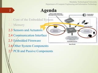
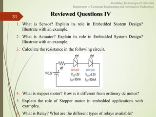


The document provides an introduction to embedded systems, covering key topics like sensors and actuators, memory, communication interfaces, firmware, and other system components. It discusses sensors that convert physical variables to electrical signals and actuators that convert signals to physical actions. Memory types for embedded systems like ROM, RAM, and flash memory are also covered.


![Embedded System[586]](https://cdn.slidesharecdn.com/ss_thumbnails/viisemesterindustrialtrainingreportpawan586-171104035355-thumbnail.jpg?width=640&height=640&fit=bounds)