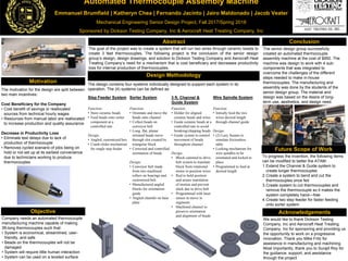
The document describes an automated thermocouple assembly machine designed by a senior design group to address the needs of Dickson Testing Company and Aerocraft Heat Treating Company. The machine feeds ceramic beads onto wires to create 3-foot long thermocouples using four subsystems: a step feeder to store and feed beads, a sorter to orient the beads, a 3-foot channel and guide to move the beads along the wires, and a wire spindle system to feed the wires. The total cost of the machine was $950 and it was designed to complete the thermocouple assembly process with little human interaction in a streamlined and economical manner.
1. Automated Thermocouple Assembly Machine
Emmanuel Brumfield | Katheryn Chea | Fernando Jacinto | Jairo Maldonado | Jacob Veater
Mechanical Engineering Senior Design Project, Fall 2017/Spring 2018
Sponsored by Dickson Testing Company, Inc & Aerocraft Heat Treating Company, Inc
The motivation for the design are split between
two main incentives:
Cost Beneficiary for the Company
• Cost benefit of savings or reallocated
sources from technical hourly wages
• Resources from manual labor are reallocated
to increase production and quality assurance
Decrease in Productivity Loss
• Eliminate test delays due to lack of
production of thermocouple
• Removes cycled scenario of jobs being on
hold or not set up at its earliest convenience
due to technicians working to produce
thermocouples
Objective
Conclusion
Design Methodology
Abstract
Motivation
Future Scope of Work
Acknowledgements
To progress the invention, the following items
can be modified to better the ATAM:
1.Extend the Channel & Guide system to
create longer thermocouples
2.Create a system to bend and cut the
thermocouples once fed
3.Create system to cut thermocouples and
remove the thermocouple so it makes the
system completely hand—free
4.Create two step feeder for faster feeding
onto sorter system
Company needs an automated thermocouple
manufacturing machine capable of making
3ft-long thermocouples such that:
• System is economical, streamlined, user-
friendly, and safe
• Beads on the thermocouples will not be
damaged
• System will require little human interaction
• System can be used on a leveled surface
The goal of the project was to create a system that will run two wires through ceramic beads to
create 3 feet thermocouples. The following project is the conclusion of the senior design
group’s design, design drawings, and solution to Dickson Testing Company and Aerocraft Heat
Treating Company’s need for a mechanism that is cost beneficiary and decreases productivity
loss for internal production of thermocouples.
We would like to thank Dickson Testing
Company, Inc and Aerocraft Heat Treating
Company, Inc for sponsoring and providing us
the opportunity to work on a progressive
innovation. Thank you Mike Fritz for
assistance in manufacturing and machining.
Most importantly, thank you to Surajit Roy for
the guidance, support, and assistance
through the project.
The senior design group successfully
created an automated thermocouple
assembly machine at the cost of $950. The
machine was design to work with 4 sub-
components that was integrated to
overcome the challenges of the different
steps needed to make in-house
thermocouples. The manufacturing and
assembly was done by the students of the
senior design group. The material and
design was based on the desire of long-
term use, aesthetics, and design need.
The design contains four systems individually designed to support each system in its
operation. The (4) systems can be defined as:
Step Feeder System Sorter System 3 ft. Channel &
Guide System
Wire Spindle System
Function:
• Store ceramic beads
• Feed beads onto sorter
component at a
controlled rate
Design:
• Angled, customized box
• Crank-slider mechanism
for single step feeder
Function:
• Orientate and move the
beads onto channel
• Collect beads on
conveyor belt
• Long, flat, planar
oriented beads move
through slot created by
triangular block
• Corrected and controlled
orientation of beads
Design:
• Conveyor belt made
from two machined
rollers on bearings and
customized belt
• Manufactured angled
blocks for orientation
guide
• Angled chamfer on base
plate
Function:
• Holder for aligned
ceramic beads and wires
• Guide ceramic beads at a
controlled rate to avoid
breaking/chipping beads
• Guide system to control
movement of beads
throughout channel
Design:
• Block cammed to drive
belt system to translate
block from rotational
motor to position wires
• Rod to hold position
and assure translation
of motion and prevent
slack due to drive belt
• Programmed with laser
sensor to move in
segments
• Machined channel to
preserve orientation
and alignment of beads
Function:
• Initially feed the two
wires desired length
through channel guide
Design:
• (2) Lazy Susans to
simulate frictionless
table
• Locking mechanism for
wire spindles to be
orientated and locked in
place
• Programmed to feed at
desired length