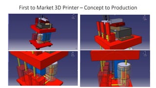
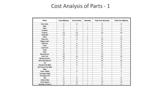
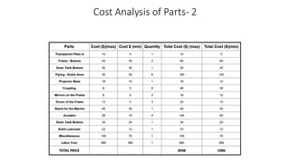
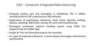
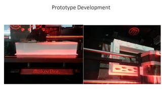
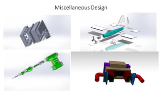
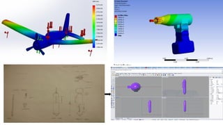
Portfolio
Kedar Ratnakar
(MSME specialized in Product Design, Controls and Manufacturing)
kedarsub@buffalo.edu
LinkedIn
Welcome
Hello,
I am a Mechanical Engineer passionate about creating innovative products
that involve design, electronics, hardware and software.
This portfolio is an introduction to my work and it will be great to interact
further with you to demonstrate how my skills, creativity, and experience will
contribute to the organization.
Please feel free to contact me regarding any questions.
Thank you for taking time to know more about me.
Key Project and Research Experience
Developed innovative Multi-Material 3D Printer
• Developed multiple concepts for printer, features and mechanisms
• Modeled and simulated in SolidWorks, validated using FEA in ANSYS
• Designed for manufacturing/assemblyand control system
• Generated cost analysis and Bill Of Materials (BOM)
• Performed customer validation of prototype
First to Market 3D Printer – Concept to Production
Assembly Video designed in SolidWorks and CATIA
(Note: Embedded video in slide): Video Link
Assembly – 2 video
(Note: Embedded video in slide): Video Link
FEA - Stress/Strain/Deflection Analysis in ANSYS
Generated Bill of Materials
Sr No Part QTY Material
1 Actuator 4 Al alloy
2 Bed 2 SS
3 Coupling 1 Al alloy
4 Doors of the Frame 2 Fiberglass
5 Drain Tank Bottom 2 SS
6 Drain Tank Bottom Fr 6 SS
7 Frame - Bottom 2 Aluminum
8 Frame - Middle 2 Aluminum
9 Frame - Top 2 Aluminum
10 Holder of Bed 2 Al alloy
11 Housing of the Wiper 2 Al alloy
12 Idle Frame for the Viper 2 Al alloy
13 Idler Gear for Timin 8 Plastic
14 Lead Screws on Z axis 2 SS
15 Lubricant Layer 2 Graphite
16 Mirrors on the Frame 2 Glass
17 Motor 4 SS
18 Piping - Entire Assembly 2 Plastic
19 Projector 2 Plastic
20 Projector Base 2 Plastic
21 Reservior 6 Plastic
22 Resin Tank 6 Plastic
23 Stand for the Machine 2 SS
24 Steel Guide Ways for 4 SS
25 Symmetry of Idler Gear 4 Plastic
26 Symmetry of Z-axis guide 2 SS
27 Timing Belt 2 Rubber
28 Transparent Plate in 2 Glass
29 Vat 2 Borosilicate glass
30 Vat Support Left 2 SS
31 Vat Support Right 2 SS
32 Wiper 2 Plastic, Rubber
33 Z-axis Support 2 Al alloy
34 Coupling 1 Al alloy
Cost Analysis of Parts - 1
Cost Analysis of Parts- 2
CIM – Computer Integrated Manufacturing
• Designed product part and assemblies in SolidWorks, FEA in ANSYS,
manufactured on CNC using Feature CAM software
• Applications of prototyping, tolerances, sheet metal, injection molding,
plastics, stamping, fabrication, testing, life cycle and manufacturing
• Developed automated material handling system using PCBA, PLC
programming and ladder logic
• Design for Test and Manufacturing for the assembly
• As a part of proprietary Research, I cannot display the images and technical
specifications
Prototype Development
Design and Analysis of Gear Train
• Modeled system in SolidWorks
• Finite Element Analysis using ANSYS
• Analyzed compliance and deformations to quantify variable compliance's
Design and Analysis of Mechanical System
Compliance Analysis
Next Slide is a Poster Presentation
Construction of House using Rapid Prototyping Machine
Next Slide is a Poster Presentation
Design optimization of Gear Trains using Multi-objective Genetic Algorithm
www.buffalo.edu
DESIGN OPTIMIZATION OF GEAR TRAINS
Kedar Ratnakar
Graduate Student
Mechanical and Aerospace Engineering Department
State University of New York at Buffalo
Worm Gear Bevel GearSpur Gear
GENETIC ALGORITHM - APPLICATION
RESULTS - DISCUSSION
PROBLEM STATEMENT
Design optimization uses optimization techniques to solve engineering
problems having various parameters, objective function either to
maximize or minimize and satisfying the constraints.
Design optimization methods have many engineering applications in
Automobiles, Aerospace Industry and design of structures.
The Optimization problem is formulated as per the five step formulation
process
Project Description
Data Collection and Information
Definition of Design Variables
Optimization Criterion
Formulation of Constraints
1. Parallel
Ex: Spur Gears, Helical Gears
2. Intersecting
Ex: Straight Bevel and Spiral Bevel Gears
3. Neither Parallel nor Intersecting
Ex: Worm and Worm Gears, Crossed Helical Gears
•
INTRODUCTION
SELECTION OF OBJECTIVE FUNCTION
MULTI OBJECTIVE OPTIMIZATION
1. EFFICIENCY = This plays an vital role in power transmission and
operating point. Also the importance is taken into consideration while
selecting the stresses and the design aspects. Due to this we included
efficiency as one of our objective function.
2. CENTRE DISTANCE = The greater the accuracy the smaller the backlash
needed. Backlash is most commonly created by cutting the teeth deeper
into the gears than the ideal depth. Another way of introducing backlash
is by increasing the center distances between the gears. Backlash is
undesirable in precision positioning applicationssuch as machine tool
tables.
3. Factors which control backlash are:
1. Precision class of gears,
2.Center distance tolerance.
3. Type of fit between gears, shafts and bearings.
4. Precision accuracy of bearings,
5.Straightness and adequate support of shafts.
W ORM GEAR =
Maximize Ef f iciency F1 = -(93.962-6065.81*tan(0.909*x1+5700tan(0.909x1))
Minimize Center Distance F2 = 0.5208*x1*x2
S.T.
941.13*(x1/(x2^3)) ≥ 0
202.52/(√1(
3
𝑥1)) ≥ 0
227.22*x1*
3
𝑥1 ≥ 0
8.44*
3
𝑥1 ≥ 0
SPUR GEAR =
Maximize Ef f iciency F1 = -0.033X1
Minimize Center Distance F2 = 6*X2+0.5*X2*X3
S.T. 1.778/X2 ≥ 0
1.06(
𝑋3
3
𝑋2
) ≥ 0
30.12
3
𝑋2≥ 0
0.309
3
𝑋2≥ 0
X1 ≥ 22
WORM GEAR =
Maximize Ef f iciency F1 = -0.167*X1
Minimize Center Distance F2 = 10*X2 + 0.5*X2*X3
S.T 2.67 / X2 ≥ 0
1068.03 / 𝑋3 ≥ 0
16
3
𝑋2≥ 0
0.46
3
𝑋2≥ 0
X1 ≥ 4.5
In fact the global minimum of multi-objective function
cannot be found. Any solution for which f(x*)<f(x) for any
point x* which improves the current solution is called local
minimum. The plot of points of one objective function
versus the other gives a Pareto region. This region is very
helpful in determining and finalizing the best possible
solution.
In short, for multi objective
function we can never have the
global solution but we can try to
get the best possible solution
satisfying the constraints.
o Genetic Algorithm: This
Algorithm is based on a
process similar to
natural selection. It uses
concepts like inheritance,
mutation, selection and
crossover.
Conclusion: This project is concluded with results for three
gears namely Worm gear, Spur gear and Bevel gear. It is
concluded that optimal solution of a multi objective function
clearly depends on the weightage of the parameters of the
objective functions and with different weights, we can get
different spread of points which are better than the initial
points. Thus a perfectly generalized optimal solution is not
possible but based on application requirement, selection of
generations, population and design points gives highly
accurate results. In this case, the results are in form of one
objective function versus other and they compete to give
optimal solution. This spread is known as Pareto Spread
which gives the possible optimal solutions. Hence we can get
optimal points for multi objective function fora specific
application.
This plot compares objective 1 vs objective 2 and gives us a spread of points
which are possible optimal solution.
WORM GEAR = The number of points on the
Pareto front was: 26
The number of generations was : 152
Initial bound : (x1,x2)= (24,4)
Upper bound : (x1,x2)= (240,7)
(f1,f2)= (-9.5,54), (-8.9,54), (0,50), (-9.6,54)
SPUR GEAR = The number of points on the
Pareto front was: 1
The number of generations was : 154
Initial bound: (x1,x2,x3) = (22, 12, 4)
Final bound : (x1,x2, x3) = (25, 36, 7)
(f1,f2)= (-4.175, 144)
BEVEL GEAR=The number of points on the
Pareto front was: 42
The number of generations was : 179
Initial bound: (x1,x2,x3) = (4.5, 8, 4)
Final bound : (x1,x2, x3) = (6, 24, 7)
(f1,f2)= (-1,96)
Design of Robotic Systems - Segway and Line follower robot
• Designed and programmed PID loop on PLC in Lego EV3 kit with stability
analysis, error calibration using sensors
• Designed controller, checked for controllability and observability
• Tested for different conditions, integrated mechanical, electronics and
software aspects for complete system
Design of Robotic Systems
Segway – Theoretical Design
• Performed mathematicalanalysisfor controllerdesign using modern control theory
• Utilized PID for actual implementation
Practical Implementation of PID – Dynamic Control System
Line Follower Robot – Program and Implementation
3D Model Generation for Manufacturing/3DP
• Generated softwarecode to load model information from ASCII/Binary files
• Developed interface to read data and develop model by triangle matrix
calculation
• Formulated method to analyze manufacturability and 3D printing capability of
that product using data
3D Model Generation - ASCII/Binary files for Manufacturing/3DP
Vertices = 3720
Faces = 1240
Faces=228
Vertices= 684
Complex Part Generation
Faces= 1476
Vertices= 4428
Faces=1946
Vertex= 5838
Arduino Applications for Electro-Mechanical Systems
Deployed a real time control system which used raw sensor readings and
controlled multiple servo motors and actuators
Some Images of Project
Other Projects
• Review Paper on Automated Weld Defect Detection System
• Material Analysis for Advanced Applications: Mechanical, thermal, electrical and chemical
property analysis for design, manufacturing and process requirements
• Failure Mode and Effect Analysis (FMEA): FMEA - DFMEA, PFMEA, root cause analysis
• Experimental Design of Stabilized Power supply from Batteries: Developed system for
stable power using electronics, IGBT, opto-couplers, DC-AC-DC converter inverter, phase
converters
• HVAC – Solar Decathlon 2015 sponsored by U.S Department of Energy: Performed design
calculations for heating/cooling loads considering location, internal loads, ventilation,
infiltration, equipment’s using ASHRAE standards. Validated energy model and monitoring
using eQuest, used Revit for duct layout
Developed optimization model utilizing renewable energy
sources like biogas, solar and wind in integration
Validated Model using Real World Data
Developed Algorithm for Selection Criteria of Floating Wind
Turbine Configuration
Miscellaneous Design
Web Development and Programming
• Web Development: Learned and created the basis of website using HTML-CSS and responsive
design using Bootstrap. Integration of JavaScript, jQuery and AngularJS framework with basic
understanding of AJAXand NodeJS
• Android Development (Eclipse SDK, Android Studio, Java): Understood android platform,
development environment, application fundamentals. App development concepts and application
(activity, intent, fragment, interface UI, content provider, services classes, notifications, broadcast,
handlers, threading, async tasks, graphics and animation, touch and gestures, multimedia and
data management)
• Programming Projects: Courses and implementation of algorithms and data structures in Java and
CS50 appliance in C. Built cash register using JavaScript, built classes in python, banking on ruby,
WEPAY API on python. Routes, directives with scope, services and reusable directives in
AngularJS, used REGEX, managed packages on cloud9.Established virtual machines,
understanding of basics in firmware, Pig and map reduce
Thank you

Portfolio

  • 1.
    Portfolio Kedar Ratnakar (MSME specializedin Product Design, Controls and Manufacturing) kedarsub@buffalo.edu LinkedIn
  • 2.
    Welcome Hello, I am aMechanical Engineer passionate about creating innovative products that involve design, electronics, hardware and software. This portfolio is an introduction to my work and it will be great to interact further with you to demonstrate how my skills, creativity, and experience will contribute to the organization. Please feel free to contact me regarding any questions. Thank you for taking time to know more about me.
  • 3.
    Key Project andResearch Experience
  • 4.
    Developed innovative Multi-Material3D Printer • Developed multiple concepts for printer, features and mechanisms • Modeled and simulated in SolidWorks, validated using FEA in ANSYS • Designed for manufacturing/assemblyand control system • Generated cost analysis and Bill Of Materials (BOM) • Performed customer validation of prototype
  • 5.
    First to Market3D Printer – Concept to Production
  • 6.
    Assembly Video designedin SolidWorks and CATIA (Note: Embedded video in slide): Video Link
  • 7.
    Assembly – 2video (Note: Embedded video in slide): Video Link
  • 8.
  • 9.
    Generated Bill ofMaterials Sr No Part QTY Material 1 Actuator 4 Al alloy 2 Bed 2 SS 3 Coupling 1 Al alloy 4 Doors of the Frame 2 Fiberglass 5 Drain Tank Bottom 2 SS 6 Drain Tank Bottom Fr 6 SS 7 Frame - Bottom 2 Aluminum 8 Frame - Middle 2 Aluminum 9 Frame - Top 2 Aluminum 10 Holder of Bed 2 Al alloy 11 Housing of the Wiper 2 Al alloy 12 Idle Frame for the Viper 2 Al alloy 13 Idler Gear for Timin 8 Plastic 14 Lead Screws on Z axis 2 SS 15 Lubricant Layer 2 Graphite 16 Mirrors on the Frame 2 Glass 17 Motor 4 SS 18 Piping - Entire Assembly 2 Plastic 19 Projector 2 Plastic 20 Projector Base 2 Plastic 21 Reservior 6 Plastic 22 Resin Tank 6 Plastic 23 Stand for the Machine 2 SS 24 Steel Guide Ways for 4 SS 25 Symmetry of Idler Gear 4 Plastic 26 Symmetry of Z-axis guide 2 SS 27 Timing Belt 2 Rubber 28 Transparent Plate in 2 Glass 29 Vat 2 Borosilicate glass 30 Vat Support Left 2 SS 31 Vat Support Right 2 SS 32 Wiper 2 Plastic, Rubber 33 Z-axis Support 2 Al alloy 34 Coupling 1 Al alloy
  • 10.
  • 11.
  • 12.
    CIM – ComputerIntegrated Manufacturing • Designed product part and assemblies in SolidWorks, FEA in ANSYS, manufactured on CNC using Feature CAM software • Applications of prototyping, tolerances, sheet metal, injection molding, plastics, stamping, fabrication, testing, life cycle and manufacturing • Developed automated material handling system using PCBA, PLC programming and ladder logic • Design for Test and Manufacturing for the assembly • As a part of proprietary Research, I cannot display the images and technical specifications
  • 13.
  • 14.
    Design and Analysisof Gear Train • Modeled system in SolidWorks • Finite Element Analysis using ANSYS • Analyzed compliance and deformations to quantify variable compliance's
  • 15.
    Design and Analysisof Mechanical System
  • 16.
  • 17.
    Next Slide isa Poster Presentation Construction of House using Rapid Prototyping Machine
  • 19.
    Next Slide isa Poster Presentation Design optimization of Gear Trains using Multi-objective Genetic Algorithm
  • 20.
    www.buffalo.edu DESIGN OPTIMIZATION OFGEAR TRAINS Kedar Ratnakar Graduate Student Mechanical and Aerospace Engineering Department State University of New York at Buffalo Worm Gear Bevel GearSpur Gear GENETIC ALGORITHM - APPLICATION RESULTS - DISCUSSION PROBLEM STATEMENT Design optimization uses optimization techniques to solve engineering problems having various parameters, objective function either to maximize or minimize and satisfying the constraints. Design optimization methods have many engineering applications in Automobiles, Aerospace Industry and design of structures. The Optimization problem is formulated as per the five step formulation process Project Description Data Collection and Information Definition of Design Variables Optimization Criterion Formulation of Constraints 1. Parallel Ex: Spur Gears, Helical Gears 2. Intersecting Ex: Straight Bevel and Spiral Bevel Gears 3. Neither Parallel nor Intersecting Ex: Worm and Worm Gears, Crossed Helical Gears • INTRODUCTION SELECTION OF OBJECTIVE FUNCTION MULTI OBJECTIVE OPTIMIZATION 1. EFFICIENCY = This plays an vital role in power transmission and operating point. Also the importance is taken into consideration while selecting the stresses and the design aspects. Due to this we included efficiency as one of our objective function. 2. CENTRE DISTANCE = The greater the accuracy the smaller the backlash needed. Backlash is most commonly created by cutting the teeth deeper into the gears than the ideal depth. Another way of introducing backlash is by increasing the center distances between the gears. Backlash is undesirable in precision positioning applicationssuch as machine tool tables. 3. Factors which control backlash are: 1. Precision class of gears, 2.Center distance tolerance. 3. Type of fit between gears, shafts and bearings. 4. Precision accuracy of bearings, 5.Straightness and adequate support of shafts. W ORM GEAR = Maximize Ef f iciency F1 = -(93.962-6065.81*tan(0.909*x1+5700tan(0.909x1)) Minimize Center Distance F2 = 0.5208*x1*x2 S.T. 941.13*(x1/(x2^3)) ≥ 0 202.52/(√1( 3 𝑥1)) ≥ 0 227.22*x1* 3 𝑥1 ≥ 0 8.44* 3 𝑥1 ≥ 0 SPUR GEAR = Maximize Ef f iciency F1 = -0.033X1 Minimize Center Distance F2 = 6*X2+0.5*X2*X3 S.T. 1.778/X2 ≥ 0 1.06( 𝑋3 3 𝑋2 ) ≥ 0 30.12 3 𝑋2≥ 0 0.309 3 𝑋2≥ 0 X1 ≥ 22 WORM GEAR = Maximize Ef f iciency F1 = -0.167*X1 Minimize Center Distance F2 = 10*X2 + 0.5*X2*X3 S.T 2.67 / X2 ≥ 0 1068.03 / 𝑋3 ≥ 0 16 3 𝑋2≥ 0 0.46 3 𝑋2≥ 0 X1 ≥ 4.5 In fact the global minimum of multi-objective function cannot be found. Any solution for which f(x*)<f(x) for any point x* which improves the current solution is called local minimum. The plot of points of one objective function versus the other gives a Pareto region. This region is very helpful in determining and finalizing the best possible solution. In short, for multi objective function we can never have the global solution but we can try to get the best possible solution satisfying the constraints. o Genetic Algorithm: This Algorithm is based on a process similar to natural selection. It uses concepts like inheritance, mutation, selection and crossover. Conclusion: This project is concluded with results for three gears namely Worm gear, Spur gear and Bevel gear. It is concluded that optimal solution of a multi objective function clearly depends on the weightage of the parameters of the objective functions and with different weights, we can get different spread of points which are better than the initial points. Thus a perfectly generalized optimal solution is not possible but based on application requirement, selection of generations, population and design points gives highly accurate results. In this case, the results are in form of one objective function versus other and they compete to give optimal solution. This spread is known as Pareto Spread which gives the possible optimal solutions. Hence we can get optimal points for multi objective function fora specific application. This plot compares objective 1 vs objective 2 and gives us a spread of points which are possible optimal solution. WORM GEAR = The number of points on the Pareto front was: 26 The number of generations was : 152 Initial bound : (x1,x2)= (24,4) Upper bound : (x1,x2)= (240,7) (f1,f2)= (-9.5,54), (-8.9,54), (0,50), (-9.6,54) SPUR GEAR = The number of points on the Pareto front was: 1 The number of generations was : 154 Initial bound: (x1,x2,x3) = (22, 12, 4) Final bound : (x1,x2, x3) = (25, 36, 7) (f1,f2)= (-4.175, 144) BEVEL GEAR=The number of points on the Pareto front was: 42 The number of generations was : 179 Initial bound: (x1,x2,x3) = (4.5, 8, 4) Final bound : (x1,x2, x3) = (6, 24, 7) (f1,f2)= (-1,96)
  • 21.
    Design of RoboticSystems - Segway and Line follower robot • Designed and programmed PID loop on PLC in Lego EV3 kit with stability analysis, error calibration using sensors • Designed controller, checked for controllability and observability • Tested for different conditions, integrated mechanical, electronics and software aspects for complete system
  • 22.
    Design of RoboticSystems Segway – Theoretical Design • Performed mathematicalanalysisfor controllerdesign using modern control theory • Utilized PID for actual implementation
  • 23.
    Practical Implementation ofPID – Dynamic Control System
  • 24.
    Line Follower Robot– Program and Implementation
  • 25.
    3D Model Generationfor Manufacturing/3DP • Generated softwarecode to load model information from ASCII/Binary files • Developed interface to read data and develop model by triangle matrix calculation • Formulated method to analyze manufacturability and 3D printing capability of that product using data
  • 26.
    3D Model Generation- ASCII/Binary files for Manufacturing/3DP Vertices = 3720 Faces = 1240 Faces=228 Vertices= 684
  • 27.
    Complex Part Generation Faces=1476 Vertices= 4428 Faces=1946 Vertex= 5838
  • 28.
    Arduino Applications forElectro-Mechanical Systems Deployed a real time control system which used raw sensor readings and controlled multiple servo motors and actuators
  • 29.
  • 30.
    Other Projects • ReviewPaper on Automated Weld Defect Detection System • Material Analysis for Advanced Applications: Mechanical, thermal, electrical and chemical property analysis for design, manufacturing and process requirements • Failure Mode and Effect Analysis (FMEA): FMEA - DFMEA, PFMEA, root cause analysis • Experimental Design of Stabilized Power supply from Batteries: Developed system for stable power using electronics, IGBT, opto-couplers, DC-AC-DC converter inverter, phase converters • HVAC – Solar Decathlon 2015 sponsored by U.S Department of Energy: Performed design calculations for heating/cooling loads considering location, internal loads, ventilation, infiltration, equipment’s using ASHRAE standards. Validated energy model and monitoring using eQuest, used Revit for duct layout
  • 31.
    Developed optimization modelutilizing renewable energy sources like biogas, solar and wind in integration
  • 32.
    Validated Model usingReal World Data
  • 33.
    Developed Algorithm forSelection Criteria of Floating Wind Turbine Configuration
  • 34.
  • 36.
    Web Development andProgramming • Web Development: Learned and created the basis of website using HTML-CSS and responsive design using Bootstrap. Integration of JavaScript, jQuery and AngularJS framework with basic understanding of AJAXand NodeJS • Android Development (Eclipse SDK, Android Studio, Java): Understood android platform, development environment, application fundamentals. App development concepts and application (activity, intent, fragment, interface UI, content provider, services classes, notifications, broadcast, handlers, threading, async tasks, graphics and animation, touch and gestures, multimedia and data management) • Programming Projects: Courses and implementation of algorithms and data structures in Java and CS50 appliance in C. Built cash register using JavaScript, built classes in python, banking on ruby, WEPAY API on python. Routes, directives with scope, services and reusable directives in AngularJS, used REGEX, managed packages on cloud9.Established virtual machines, understanding of basics in firmware, Pig and map reduce
  • 37.