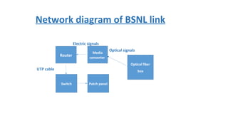
1. • Networking is way by which a computer can share it’s data or
information to other computer or group of computers.
• The connection between two computers are though cable , media or
wire less systems.
• The computers are arranged in some topology, according to the need.
• Network computer devices that originate, route and terminate the
data are called network nodes.
• Nodes can include host such as personal computers, phones, servers
as well as networking hardware.
Networking
2. • Media
• Media converter
• Router
• Switch
• Patch panel
• Device you want to connect.
Requirements of a basic network
3. Media, is through which the information flows from transmitting end
to the receiving end.
•There are of two types
Guided
Unguided
•Guided media is further divided as-:
•Twisted pair cable.
UTP(unshielded twisted pair cable)
STP(shielded twisted pair cable)
•Coaxial cable
•Optical Fiber cable
single mode
multi mode
Media
4. • Unguided type of media
• Radio wave
• Micro wave
• Infra red
5. • The device which is used to connect two dissimilar media types such
as twisted pair to fiber optic .
• Although this device is not compulsory for formation of a network but
plays a vital role in arranging large scale networks.
• Media converter types range from small standalone devices and pc
card converters to high port-density chassis systems that offer many
advanced features for network management.
Media converter
6. • A router is a device that forwards data packets along networks.
A router is connected to at least two networks, commonly two LANs
or WANs or a LAN and its ISP's network. Routers are located at
gateways, the places where two or more networks connect.
• Router configuration
• We configure a router to make our network complete , that is we
need to configure a router to let the router and other devices
communicate in the network.
Router and it’s configuration
7. • To configure a router first of all we need to enable a router using enable
command.
• Then we have to connect it to the interface, using interface command
and specifying which cable we are using.
• Now we use no shut down command to get connected to the interface.
• Then we can provide the router an IP, using IP address command.
• We can also provide password and user name to the route .
• We can also set the banner using banner command.
Steps of router configuration
8. Show running-configuration - Displays configuration currently
in RAM
Show startup-configuration - Displays configuration file
NVRAM
Show IP route - Displays routing table
Show interfaces - Displays all interface configurations
Show IP int brief - Displays abbreviated interface configuration
information
Some other basic command for router
configuration
9. A network switch is a computer network device that connects devices
together on a computer network, by using packet switching , to receive,
process and forward data to the destination device. Unlike less
advanced network hubs a network switch forwards data only to one or
multiple devices that need to receive it, rather than broadcasting the
same data out of each of its ports.
Switch
10. • To configure the default gateway for the switch, use the IP default-
gateway command. Enter the IP address of the default gateway. The
default gateway is the IP address of the router interface to which
the switch connects. Use the following command to backup
the configuration: copy running-config startup-config.
Switch configuration
11. Patch panel is a device or unit featuring a number of jacks, usually of
the same or similar type, for the use of connecting and routing circuits
for monitoring, interconnecting, and testing circuits in a convenient,
flexible manner. Patch panels are commonly used in computer
networking , recording studios , radio and televisions .
The patch panels are further connected to switch for the fair
distribution of the network signals.
Patch panel
12. ws domains provide network administrators with a way to manage a large number of PCs and control them from o
more servers — known as domain controllers — have control over the domain and the computers on it.
s are generally made up of computers on the same local network.
er, computers joined to a domain can continue communicating with their domain controller over Internet connect
ows businesses and schools to remotely manage laptops they provide to their employees and students.
computer is joined to a domain, it doesn’t use its own local user accounts.
ccounts and passwords are managed on the domain controller.
you log into a computer on that domain, the computer authenticates your user account name and password with
n controller.
eans you can log in with the same username and password on any computer joined to the domain.
What is domain ?
13. Network diagram of Ashokleyland
PNR
ALWAR
H1
COSTUME
R
H1
ALCOB
H2
DEALER
EDC
S&D
WARE
HOUSE
RSO
BHAN
SUPPL
IERS
SRM
portal
Disaster management
unit
DMS
portal
CRM
portal
14. The heart of the network structure of Ashok Leyland is Ennore Data
Center (EDC) , every request generated at any point at the network first
goes to EDC and then the request is generated at the required station.
The EDC is connected to all the stations of the chart directly.
EDC has a disaster management unit which is Hosur 1, it backups all the
data a EDC just after the five minutes of it’s arrival i.e.. in case of any
disaster the loss of data will only be of five minutes to the company.
The EDC is directly connected to costumers, dealers and suppliers
directly through CRM portal , SRM portal and DMS portal.
15. • Ashokleyland uses several portals to stay connected to suppliers, costumers
and dealers.
• A portal site is framework or a specially designed website which is used to
bring information together in an uniform way and also helps to share
information.
• SRM portal – Supplier Requirement Manager, this portal is used to get
connected to suppliers and to manage companies requirements.
• CRM portal – Costumer Requirement Manager, this portal is used to get
connected to costumers and to manage their requirements.
• DMS portal – Dealer Management System, this is used for to get connected
to dealers requirements .
17. Assembly line 1924
PPC 1924
P & A 1912
12COREMMF
4COREMMF
ADMIN BLOCK 1924
10mbpsmediaconverter
100 mbps media converter
10 mbps media converter
6COREMMF
6COREMMF
6 CORE MMF
SERVER ROOM
29242924
RSO
MAIN GATE
SHOP-2
NETWORK LAY OUT OF ALWAR UNIT
18. Ashok Leyland has two network connections one of Reliance and other
of BSNL, network is equally divided into both the connecting links
equally but if anything went wrong in any one of them the whole work
load can be shifted to one, making work process slow but not letting it
stop hence any of the link can work as backup as well .
Network structure of Alwar unit
20. The Ashokleyland Alwar unit has a radio wave antenna for it’s reliance link the
signals are further converted into electrical signals with the help of a converter
and these electrical signals are then passed through power of Ethernet , it is a
device which pass electrical power along with data on twisted pair cables .This
allows a single cable to provide both data connection and electrical power, the
signals can be transferred to long cable lengths by using this device. Than the
signals are passed through media converter although media converter is not a
compulsory element in this type of networks , after this the signals pass through
router which helps in forwarding the data packets in the network and building
communication between all the devices connecting in the network. lastly the
electrical signals are passed though switch and patch panel witch helps in
distribution.
Network connection through reliance links
22. The Ashokleyland Alwar uses optical fiber for it’s BSNL link the optical fiber
signals comes directly from BSNL local exchange ,then these optical signals
go to media converter, the media converter is one of the most important
part of this network as it allows to connect to type of signals , optical and
electrical which implies that these optical signals passes though media
converter and forms electrical signals which passes through UTP an d is
supplied to router afterwards , the router helps in forwarding the data
packets and letting the other device communicate connecting in the
network , then the signals pass through switch and patch which are use to
distribute the signals.
Network connection through BSNL link
24. At the user side the UDP cable is connected to the patch panel which is
used for monitoring, interconnecting, and testing circuits in a
convenient, flexible manner. The signals then are passed through a
switch which distributes the network signals and then the signals are
received by the receiver through IO ports .
Network structure at the receiver end